1. Introduction
The number of consumer electronic devices, such as smartphones, laptops, and high-definition devices, has increased in recent decades. Most of them use Wi-Fi as their primary wireless connectivity. Wi-Fi, a de facto wireless local area network (WLAN) standard developed for over two decades, is based on the IEEE 802.11 family of standards, commonly used for wireless local area networks for devices.
IEEE 802.11 supports a contention-based media access protocol called distributed coordination function (DCF), for accessing the wireless medium. Specifically, the device with DCF tries to access the medium unless the medium is busy during the predefined interval called DCF inter-frame space (DIFS). Therefore, when multiple stations sense the idle medium, they try to access the medium simultaneously, and a collision may occur accordingly. To avoid such collisions, DCF also specifies a random backoff mechanism, which forces every station to defer their access to the medium for a randomly chosen extra period. Since DCF is a fundamental approach for the medium access of IEEE 802.11, a significant number of results on the DCF have been published, where the throughput of 802.11 DCF has been analyzed by a simple Markov chain model.
Meanwhile, the extreme high throughput (EHT) task group has been working on a new amendment entitled IEEE 802.11be [
1], which defines EHT PHY and MAC layers capable of the maximum throughput of at least 30 Gbps with improved worst-case latency. Task group-be (TGbe) has agreed to adopt a release framework because it has a major impact on competitive technology, market expectations for new uses, and product launch dates. Features incorporated in the Release 1 will be prioritized in the standardization process of 11be are wideband spectrum utilization, EHT PHY layer protocol data units (PPDUs) on the PHY layer, and multi-link operation on the MAC layer. On the other hand, features that are likely to be included in the Release 2 will mature later [
2]. Among new features newly introduced in IEEE 802.11be Release 1, multi-link operation, which enables a single physical device to establish multiple links and operate them simultaneously, is the most representative feature of the IEEE 802.11be in that the multi-link operation can provide efficient use of the available spectrum. Therefore, it can achieve higher data rates than the conventional single-link operation and can implement load balancing.
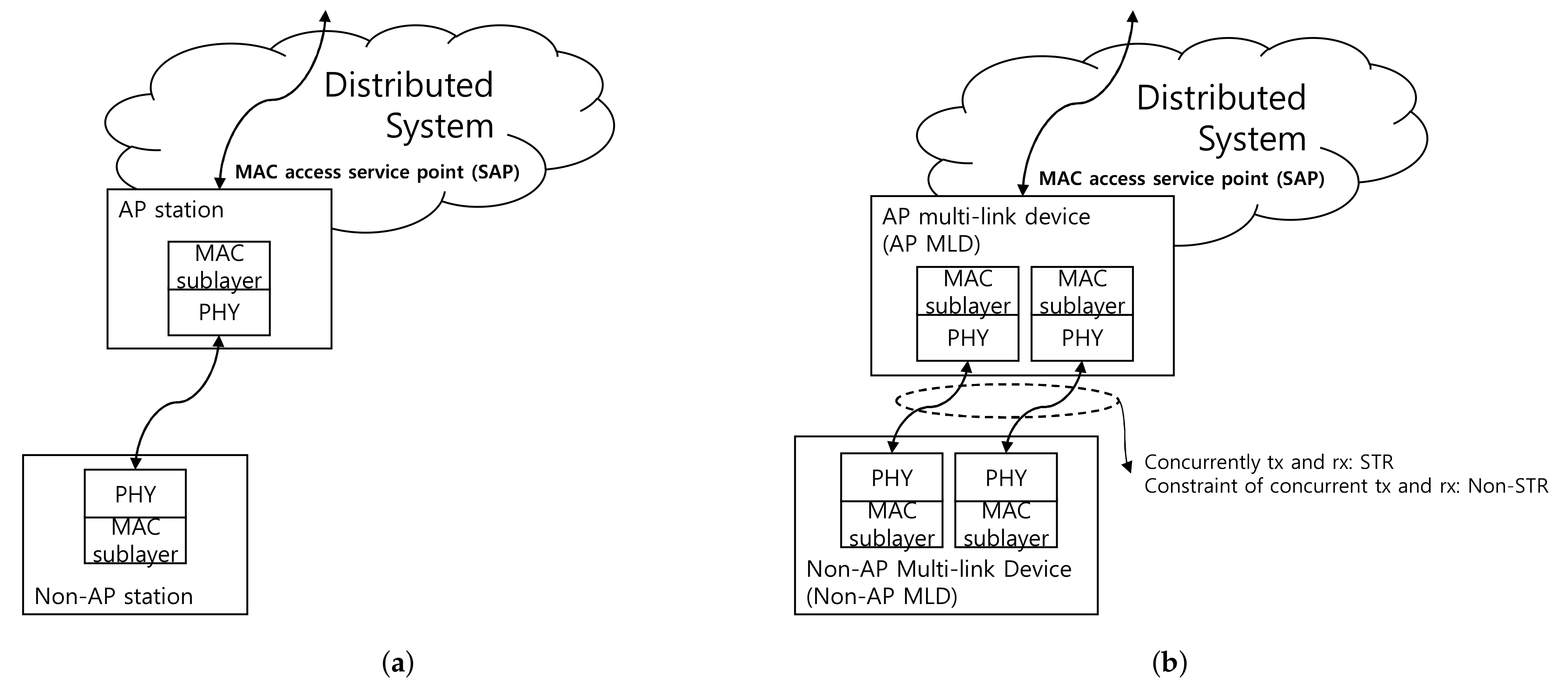
When it comes to multi-link operation in terms of IEEE 802.11be standardization, a new entity called multi-link device (MLD) has been defined [
3]. This MLD is a physical device with more than one affiliated station and has one interface toward the upper layer. Consequently, such MLDs can transmit and receive simultaneously in different bands or links, such as 2.4 GHz, 5 GHz, and 6 GHz, and thus they can increase the peak throughput by enabling simultaneous operations.
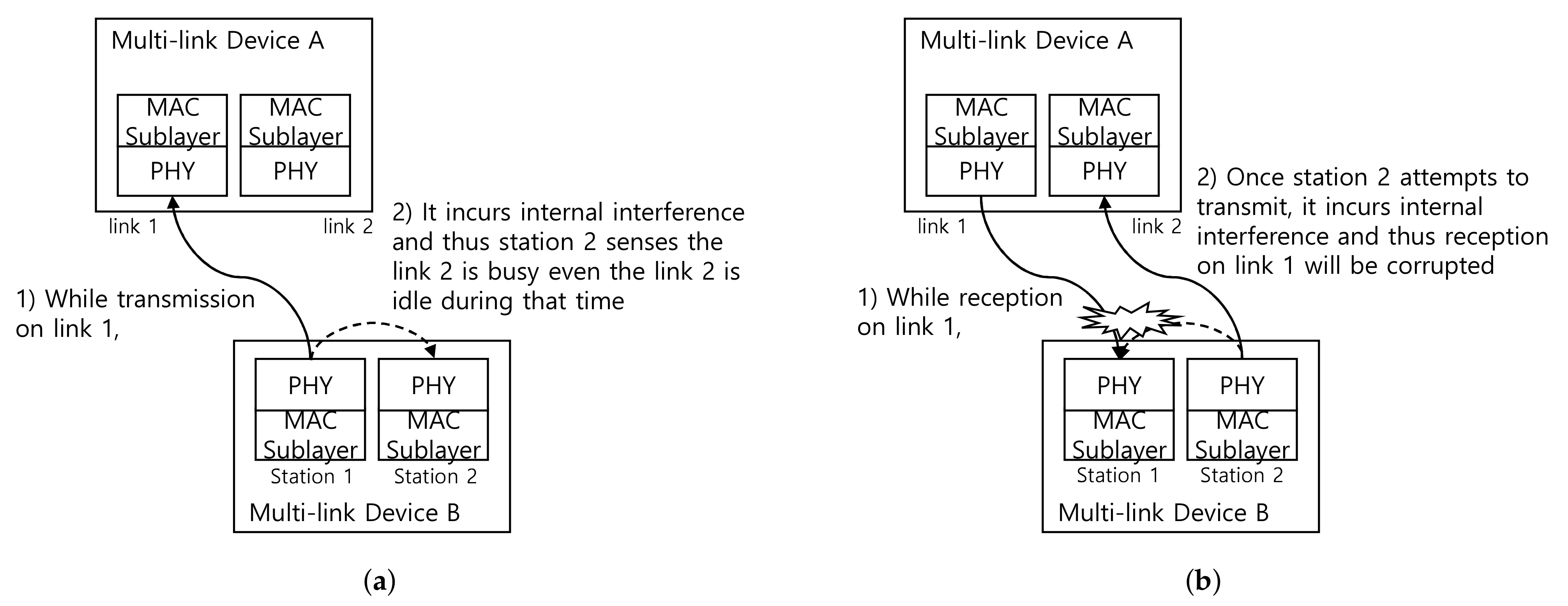
However, it is not always possible to freely use these multiple links. For example, a transmission from one of the MLD links can affect receptions over other links within the same MLD, and thus the reception may fail due to in-device interference from transmission power leakage inside the MLD. For example, this phenomenon may happen if the center frequencies of the MLD links are too close. Therefore, a modified multi-link operation is required to deal with the in-device interference mentioned above. For this purpose, a synchronous transmission method in which the end times of transmissions from the same MLD must be aligned in the same MLD has been claimed to avoid in-device interference. As synchronous multi-link transmission behavior has not been considered in the conventional 802.11, a modified DCF suitable for synchronous multi-link must be devised.
Although a detailed DCF procedure for multi-link has not been standardized in 802.11be yet, several modified DCF methods to support synchronous multi-link operation have been proposed during TGbe, and their performance evaluations are being made. However, to the best of our knowledge, none of the researches has introduced an analytical model for the synchronous multi-link DCFs.
The main contributions of this work are three-fold: (1) We investigate multi-link DCFs applicable for synchronous multi-link transmission and devise a Markov Chain model for them. (2) We analyze average throughputs and fairness between MLDs and single-link devices with extensive mathematical analysis when two links are established. (3) We discuss the advantages and disadvantages of the analyzed multi-link DCFs.
The rest of this article is organized as follows. In
Section 2, we introduce a detailed multi-link architecture and its operation discussed in IEEE 802.11be. In
Section 3 and
Section 4, we classify the proposed multi-link DCFs suitable for synchronous transmission into four types and construct Markov Chain models for each, respectively. Next, performances for the multi-link DCF methods are numerically analyzed from various perspectives in
Section 5. Finally, we conclude our work in
Section 6.
3. Design of Synchronous Multi-Link Distributed Coordination Functions
As we mentioned in
Section 2, if non-STR MLDs need to be supported, we need to consider synchronous transmissions where end times of transmission are aligned. Thus, we only focus on synchronous multi-link DCFs and model the Markov Chains based on them. We assume that an MLD has dual radios, each of which is equipped with PHY and MAC layers, and the radios of the MLDs are on the non-STR condition, which means they have constraints of simultaneous transmission and reception as seen in
Figure 2a,b.
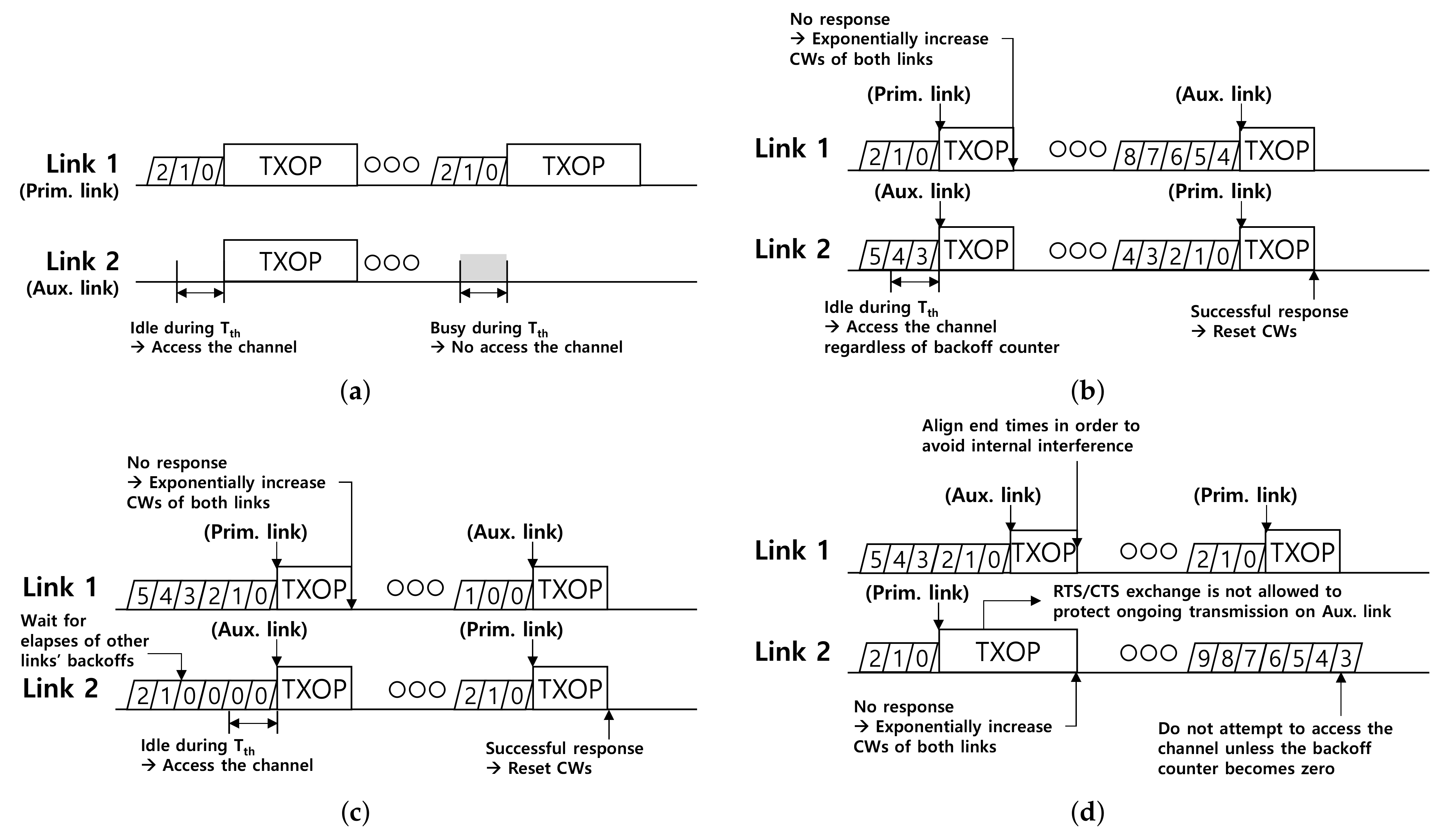
In this section, we elaborate designs of the multi-link DCFs mentioned above. Simplistic operations of the DCFs are illustrated in
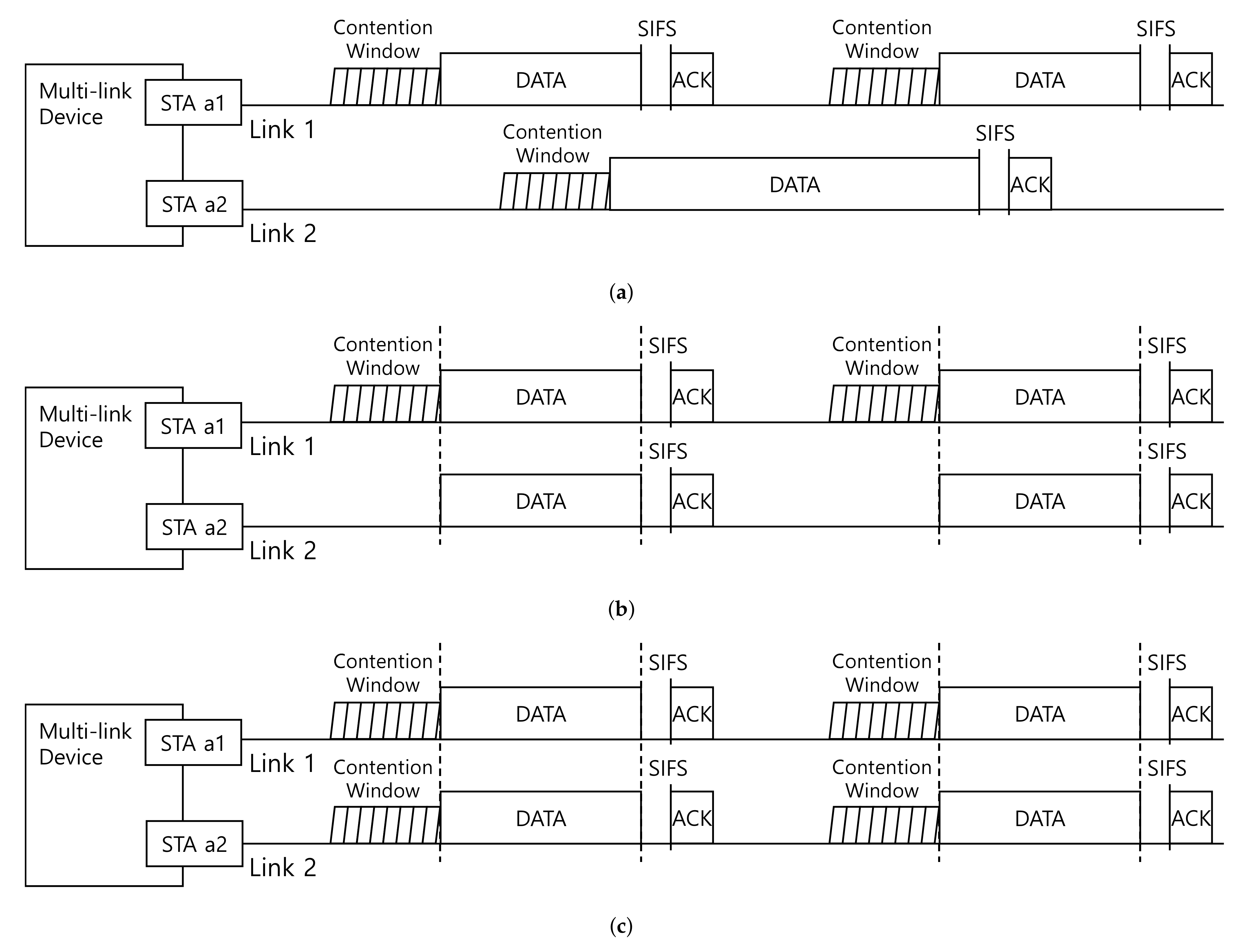
Figure 4. From now on, a link in which transmission is initiated by winning a contention is called a primary link. Transmissions on other links that rely on the transmission on the primary link may be initiated, and the link on which the transmission is initiated is referred to as an auxiliary link. Specifically, we classify the mentioned multi-link DCFs according to the channel access methodology into four following four multi-link DCFs and compare them: (1) single-link access (SLA) [
5,
6,
7], (2) multi-link access with the shortest backoff (MLA-S) [
4,
5,
8,
9,
10], (3) multi-link access with the longest backoff (MLA-L) [
12,
16], and (4) multi-link access with end-time alignment (MLA-A) [
4,
9,
17].
In the case of SLA, as shown in
Figure 4a, only one pre-defined link is eligible to access the channel, and therefore, the link shall be a primary link permanently. Once the primary link is permitted to access the channel through an expired backoff counter, the other link, which is the auxiliary link, can participate in transmission only if the channel on the links were idle during a fixed interval, which will be called by
Tth, immediately preceding the start of the transmission opportunity (TXOP). Otherwise, TXOP will set only on the primary link. In conclusion, the backoff operation only proceeds on the primary link, and there are no backoff operations on the auxiliary link.
On the other hand, accessing the channel on all active links may be allowed, unlike SLA. That is to say, all the links can be operated as primary links, which we call by multi-link access (MLA) mechanism. We next classify MLA into three cases, MLA-S, MLA-L, and MLA-A. For MLA-S, as shown in
Figure 4b, TXOP is obtained by an MLD when the backoff counter of either one of the MLD’s links is expired. At this time, the link where the transmission is initiated is set to the primary link, and the other link is set to the auxiliary link. In addition, if the auxiliary link has been idle during
Tth before TXOP starts, the channel is accessed even if the backoff counter of the other link is remaining and in consequence, the link will become the auxiliary link. For example, suppose that backoff counters of links 1 and 2 in the initial stage are set to 2 and 5, respectively, as shown at the beginning in
Figure 4b, then the backoff counter of link 1 will expire earlier, and link 1 will be the primary link. If the channel on link 2 is idle during
Tth right before TXOP on link 1, link 2 will get the opportunity to transmit the data frame. After transmission, these backoff counters are reset within the initial stage for successful transmission. In this example, they are set to 8 and 4, respectively. CW values are doubled if the transmission was failed, and the backoff counter for the next channel access will be selected with the revised CW.
MLA-L, which is shown in
Figure 4c, is slightly different with MLA-S. In MLA-L, a channel can be accessed when all backoff counters are expired for all links only. Since backoff counters of stations affiliated with the same MLD can be shared, channel access is initiated when the backoff counter of the last station becomes zero. For example, if backoff counters of links 1 and 2 are 5 and 2, respectively, as shown in
Figure 4c, then acquiring the TXOP is available after all the backoff counters are expired. In this situation, a link with the largest backoff counter becomes the primary link. On the auxiliary link, the station checks whether the link has been idle during
Tth before TXOP starts and determine participating in multi-link transmission.
In the case of MLA-A, as shown in
Figure 4d, similar to conventional DCF, each station tries to commence TXOP when the backoff counter elapses. A link where the backoff counter firstly elapses is set to the primary link. While the backoff counter is decrementing on the other link, the station can initiate a transmission if its backoff counter becomes zero while transmission on the primary link, and thus, the link is set to the auxiliary link. For example, the backoff counters of links 1 and 2 are 5 and 2, respectively. The backoff counter of link 2 will be expired earlier, and link 2 becomes the primary link. Since there is a remaining counter on link 1, the rest of the counter will also be expired soon. If there is ongoing transmission within the same MLD at the time, then the additional transmission will occur. In MLA-A, we need to focus on three things. First, since the ongoing transmission on link 2 precludes station on link 1 from checking the channel, which is shown in
Figure 2a, channel check during
Tth does not work. Second, to avoid in-device interference between links for non-STR cases, the end moments of TXOPs need to be aligned. If not, the following frames, such as acknowledgments, may occur in-device interference on the links being received, as seen in
Figure 2b. Lastly, MLA-A may not be used with RTS/CTS exchange when the CTS reception on the primary link and the transmission on the auxiliary link overlap.
4. Discrete Time Markov Chain Models and Analysis
Since a derivation procedure is applied to derive analytical models for multi-link DCFs in common, we first introduce the throughput derivation methodology here. In the header of this section, we first introduce a superb derivation with elementary conditional probability arguments [
15], which is a revised model from a two-dimensional Markov chain analysis [
14] to assist in understanding.
In order to calculate throughput, we first should solve two non-linear equations. The first is the probability
that a station transmits in a randomly chosen slot time, and the second is the value of
p that is the conditional collision probability, given that the frame has been transmitted. We hereafter introduce an elementary conditional probability approach proposed in the literature. First, to derive
, the event that an MLD is transmitting a frame in a randomly selected time slot is denoted as
. Given that the maximum retry number is
R, the event that the MLD is found in backoff stage is denoted as
, where
. To find the value of
, we can derive the below equation with Bayes’ theorem as follows:
Since Equation (
1) also holds for each
is, the equation can be written as follows:
Thus,
can be represented as follows:
Meanwhile, the conditional collision probability
p means that when a station is trying to access the channel with zero of the backoff counter, at least one remaining station tries to capture the channel with a zeroed backoff counter in the same time slot. Hence,
p can be expressed as follows:
where
n is the number of contenting stations.
is a probability that a certain station is on the
ith stage given that the station has attempted to transmit due to its zeroed backoff counter. If a recipient station has successfully received the transmission, the number of stage
i will be returned to zero. Otherwise, the number of stage
i increased by one only if a pre-defined retry number, say
R, has not been exceeded. Furthermore, since
follows geometric distribution,
can be expressed as follows:
where
p is the conditional collision probability defined in Equation (
4).
Meanwhile,
is the probability that the station is subject to attempt to access the channel in the
ith stage. Let us explain with a detailed example. The backoff counter will be selected based on uniform distribution. Assume that CW on the initial stage is 7, the backoff counter will be in the interval of
. As a result, an expected time slot duration to await becomes
. Hence,
. In this way,
can be calculated as follows:
where
is the average value of backoff counter for stage
i. In the baseline of 802.11, the initial CW, CWmin and the maximum CW, CWmax values are defined as 15 and 1023, respectively, and the retry number is 6. Since the selected backoff counter follows a uniform distribution, then
values for all
i can be represented as {7.5, 15.5, 31.5, 63.5, 127.5, 255.5, 511.5}, respectively.
We can solve two non-linear equations using Equations (
3)–(
6) with numerical techniques. After that, the throughput
S can be calculated as seen in [
14]:
where
is the probability that one or more transmissions are tried in a particular time slot,
is the probability that just one transmission is occurred and thus a successful transmission happens in a particular time slot, and
is the average length of payload. In addition,
,
, and
represent the time slot duration, the average time when a successful transmission happens, and the average time when a collision happens, respectively.
and
can be expressed depending on whether RTS/CTS is enabled or not, which is denoted as subscript letters of on and off of, as follows.
where
,
,
,
,
,
,
, and
represent the occupation time of packet header, SIFS duration, DIFS duration, the occupation time of RTS frame, the occupation time of CTS frame, the average transmit duration for payload, the occupation time of Ack frame, and the slot time, respectively.
The next section presents a 3D Markov chain model for analyzing network throughput for a multi-link DCF with two stations attached, and introduce a simpler version derived from it.
4.1. Single-Link Access (SLA)
We first build a Markov chain model for SLA, which is closely akin to the conventional Bianchi’s model, except the presence of channel access opportunity on the auxiliary link, as depicted in
Figure 4a. Let
represent the current backoff stage and the remaining backoff counter for a given station on the primary link at time
t, respectively. Since this two-dimensional random process assumes that the probability
p is independent of the backoff procedure, the time variable is omitted and the state of each station is described as
throughout this paper. In addition, since auxiliary link do not attempt to access the channel, only primary link is considered in this Markov Chain model.
Calculation procedure of
in SLA, which is represented as
, is exactly same with the procedure represented in Equation (
3) since there is only one primary link and this operation is same with conventional DCF. The difference between SLA and conventional DCF is that, there is a chance to boost throughput on the auxiliary link if the links are idle during
Tth right before attempting transmission on the primary link.
As mentioned in
Section 4 and
Figure 4a, an amount of transmitted data can be boosted if the auxiliary link has been idle during
Tth. If there is no single-link device on the link 2, where the auxiliary link of the MLD is formed as shown in
Figure 4, the transmitted data is always doubled. However, if there are single-link contenders, such as legacy stations, on the link 2, transmitted data may not get a chance to access the auxiliary link. For this case, we can revise the throughput expression as follows.
Since the DCF operates on a time-slotted manner, we let this number of checking slots as
Nth slots, which can be represented as
Nth
. Then we can express throughput equation for SLA referring to Equation (
7),
as follows:
where
represents the probability that there is at least one transmission from single-link devices on the link where the auxiliary link is formed in a randomly selected slot. In case when there are single-link devices,
can be obtained empirically or numerically by means of the Bianchi’s Markov Chain model. Otherwise,
just becomes doubled compared to conventional single-link DCF Markov Chain model. The other parameters, such as
,
, and
can be derived in the same way as given equations expressed in Equations (
8) and (
9).
4.2. Multi-Link Access with the Shortest Backoff (MLA-S)
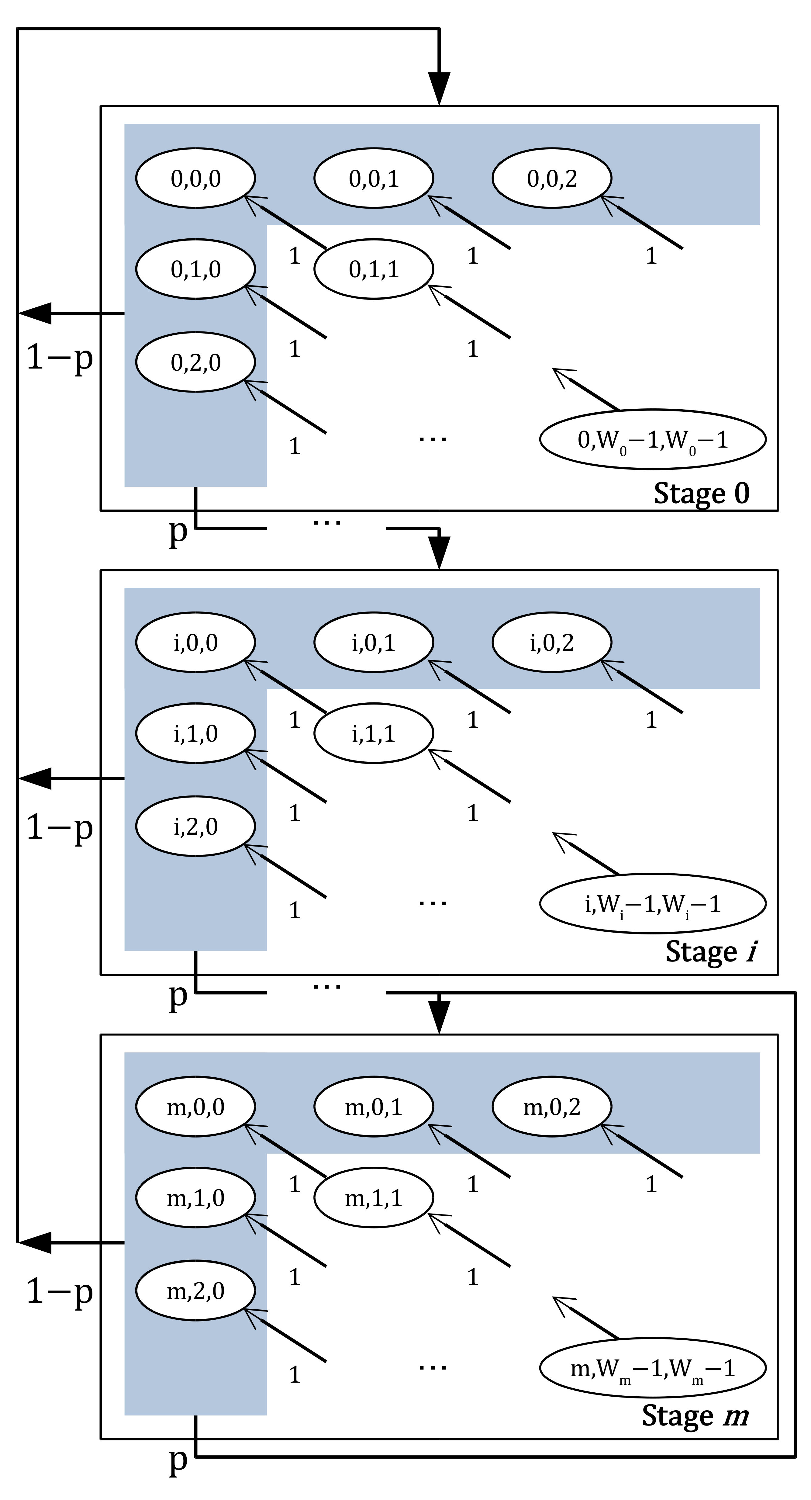
For multi-link access, channel acquisition procedures occur on multiple links. Hence, we need to construct the multi-dimensional Markov Chain model, rather than the conventional 2D Markov Chain. We design a 3D Markov Chain model of MLA-S in
Figure 5 for an MLD with two stations attached.
Let
represent the current backoff stage, the remaining backoff counter of the first station, and the remaining backoff counter of the second station, respectively. Two backoff counters,
and
are decremented at the beginning of each time slot until either backoff counter reaches to zero. Hence this case can be expressed as follows
Recall that in case of MLA-S, when just one of backoff counters reaches zero, transmissions are attempted on both links. The states where the transmission occurs are represented as blue areas in the figure. After the successful transmission on the primary link, with probability
, the state will be moved to randomly selected state in stage 0, which is the initial stage. Since there are
states in stage 0, the transition probability for transmission success case is expressed as follows:
There may be cases of transmission failure. If a transmission on the primary link is failed, the transmissions on the other link is considered as failure so that the CW should be doubled. When the stage was from zero to
, the one-step transition probability for the case of transmission failure is as follows:
Similar to Equation (
13), we can derive one-step transition probability for the transmission failure case when the backoff stage is
m.
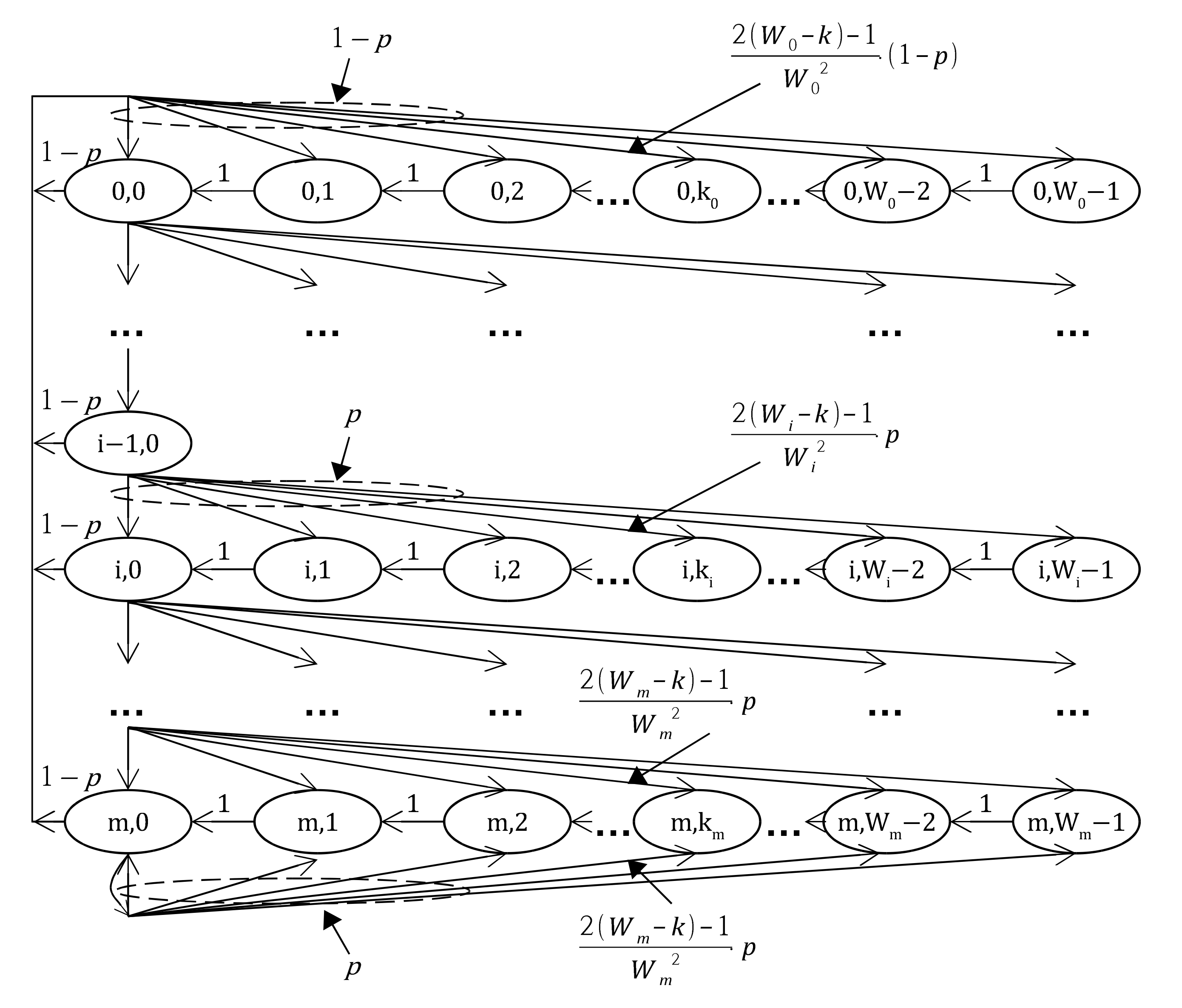
To make numerical analysis of this model simpler, we simplify the Markov Chain model as follows.
Figure 6 shows simplified 2D Markov Chain model for MLA-S. In this model, the state
represents the current backoff stage and the shortest remaining backoff counter of an MLD, that is,
.
With this simplified 2D Markov Chain, the one-step transition probabilities with two stations affiliated with an MLD are the following:
The first equation in Equation (
15) explains that when the backoff counter remains, it decreases for every time slots. The second equation account for the fact that the minimum backoff counter will be distributed after successful transmission with respect to the formula. The third and the fourth equations stand for the transition probabilities when the previous transmissions are failed. Let us elaborate the formula derivations for the second, the third, and the fourth equations as follows.
Let
be a discrete random variable of initially selected backoff counter right after transmission or collision for the particular link
n when the stage of the backoff counter is bound for the
ith stage. Since each selected backoff counter on each link is uniformly distributed and they are independent and identically distributed (i.i.d.), we can represent
as follows:
where
N is the total number of links. Let another discrete random variable
be the minimum value of
N backoff counters among
N links in stage
i, then
can be expressed as follows:
To derive one-step transition probability for the second, the third, and the fourth equations in Equation (
15), we need to come up with a probability mass function (PMF) of
. To this end, we first derive a cumulative distribution function (CDF) for the probability that the minimum backoff counter of an MLD as follows:
The PMF of
can easily be derived with the CDF which we expressed in Equation (
18) as follows:
Since we assumed there are two links, the probability that the minimum value of two backoff values is chosen to
k in stage
i is expressed as follows:
Since the second equation in Equation (
15) accounts for the successful transmission case whereas the third and the fourth equations do for the failed transmissions,
and
p are multiplied to the derived formula of Equation (
20).
Now that the Markov Chain has been constructed, we can solve
which we introduced in Equation (
3). To this end, we need to derive the conditional probabilities,
and
. First,
can be expressed same with Equation (
5) with
as follows:
For
, we need to derive the average value of backoff counter for stage
i,
. We can use the derived one-step transition probabilities, which are the second, the third, and the fourth equations in Equation (
15). Referring Equation (
3), we need to derive
for all
i. Using Equations (
6) and (
19), it can be derived as follows:
where
is the average value of backoff counter for stage
i in MLA-S case. Finally, we can get
by means of solving non-linear equations with Equations (
3), (
4), (
21) and (
22).
Next then, we can express throughput equation for MLA-S,
in a similar way to Equation (
10) since the condition for boosting channel access is the same with SLA.
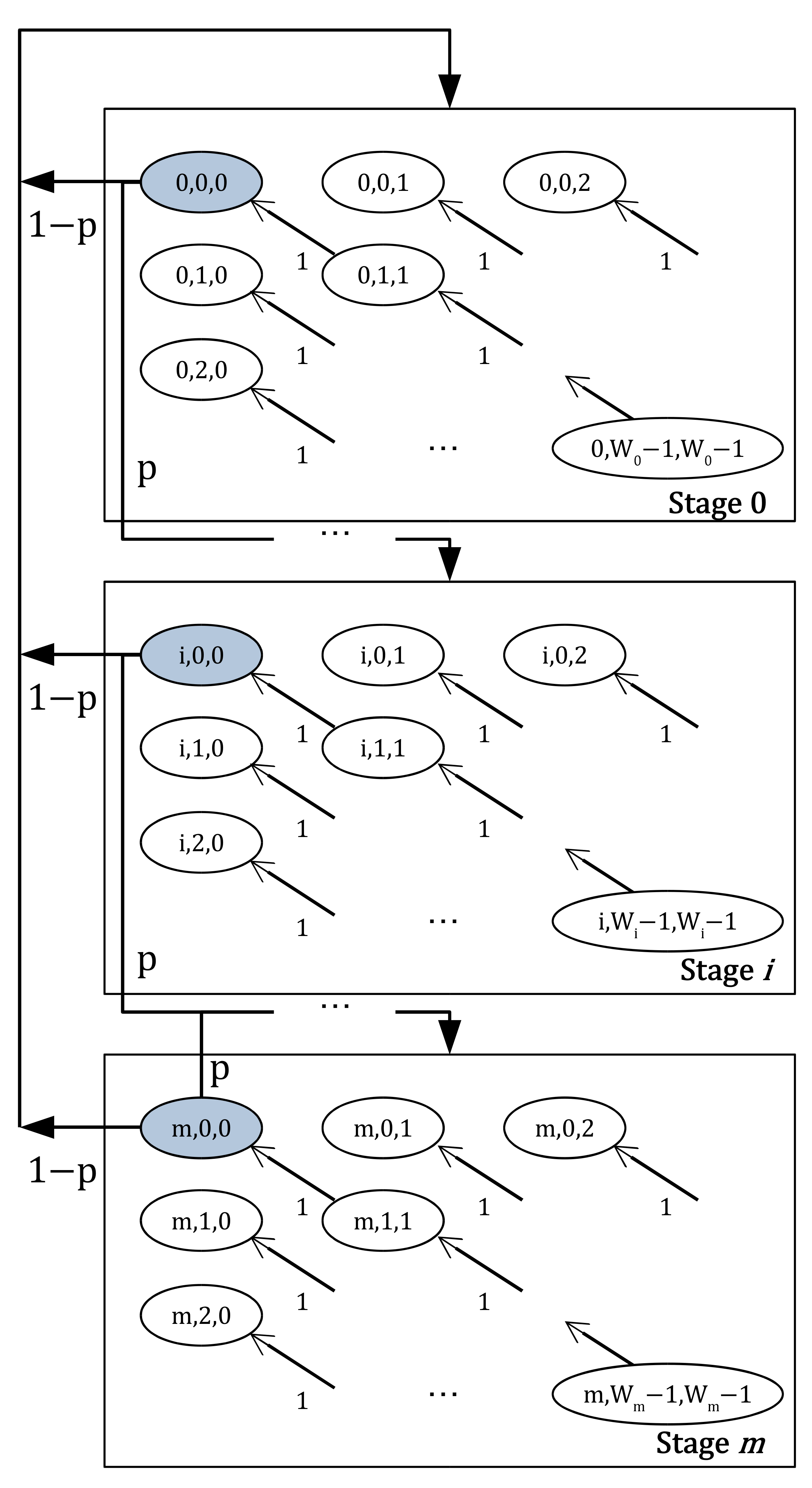
4.3. Multi-Link Access with the Longest Backoff (MLA-L)
We design a 3D Markov Chain model of MLA-L in
Figure 7 for an MLD with two stations attached. Same with the MLA-S case as mentioned in
Section 4.2, let
represent the current backoff stage, the remaining backoff counter of the first station, and the remaining backoff counter of the second station, respectively. Unlike MLA-S, two backoff counters,
and
decrease to zero at the beginning of each time slot until all backoff counters reaches to zero. Hence this case can be expressed as follows:
The states where the above-mentioned transmission occurs are represented as blue areas in the figure. After the successful transmission on the primary link, with probability
, the state will be moved to any state in the initial stage. Since there are
states on the stage 0, the transition probability for transmission success case is expressed as follows:
In cases of transmission failures, the transmissions on the auxiliary link are also considered as failure so that the CW should be doubled. When the stage was from zero to
, the one-step transition probability for the transmission failure case is as follows:
Similar to Equation (
26), we can derive one-step transition probability for transmission failure case when the backoff stage is
m as follows:
In the same manner as MLA-S, we can reduce this 3D dimensional Markov Chain model to 2D Markov Chain as shown in
Figure 8. In this model, the state
represents the current backoff stage and the longest remaining backoff counter of an MLD. The difference from MLA-S is that,
b for MLA-L is the longest remaining backoff counter among the MLD since the MLD have to wait during the longest remaining backoff counter. The one-step transmission probabilities for the Markov Chain of MLA-L with two stations affiliated with an MLD are the following:
The first equation in Equation (
28) accounts for decreasing remaining backoff counter for every time slots. The second, the third, and the fourth equations account for one-step transition probability after every transmission.
Similar to the MLA-S case, we denote a discrete random variable as follows:
with Equation (
29), we can derive CDF of
as follows:
Notice that discrete random variable
is the maximum value of
N backoff counters, contrary to
. With Equation (
29), we can derive CDF of
as follows:
As shown in
Figure 8, we can derive PMF when there are two stations attached to an MLD:
and therefore one-step transition probabilities shown in Equation (
28) can be expressed.
In the same way as MLA-S, we can solve
by means of solving non-linear equation with the followings.
and
where
is the average value of backoff counter for stage
i in MLA-L case. Then we can get
by means of solving non-linear equations with Equations (
3), (
4), (
33) and (
34).
Finally, throughput equation for MLA-L can be expressed in the same way as MLA-S, as seen in Equation (
23) with substituting
and
for
and
, respectively as follows.
4.4. Multi-Link Access with End-Time Alignment (MLA-A)
In the MLA-A case, the Markov Chain model is exactly the same as MLA-S’s. As shown in
Figure 4d, the link where the transmission starts is the link with the shortest backoff counter. The difference is that there are opportunities to access the channel during the transmission if backoff counter is expired on the other link. Hence, we just need to modify throughput equation,
.
As you can see in
Figure 4d, the station on auxiliary link needs to know how long to wait for the backoff counter to expire. To this end, an absolute difference value between two uniform random variables needs to be calculated. Denote
be the distribution of absolute difference value of two uniform random variables in the stage
i. For instance, as seen in
Figure 4d, selected backoff counters at first are 2 and 5, respectively. Assuming the MLD is in the initial stage, then
.
At first, the probability that the remaining (that is, difference) backoff counter is
k,
is as follows:
Then, the number of remaining slots in stage
i,
can be derived as follows:
This value can be approximated to
for a relatively large
. We need to derive the number of remaining slots regardless of the stage
as follows.
where
. Then, throughput equation for MLA-A can be expressed as follows:
where
stands for the data transmission duration and
represents the percentage of the average accessible time duration on auxiliary link to the average data transmission duration on primary link.
5. Performance Analysis
In this analysis, we assumed that there were two stations attached to an MLD, each of which formed a link to the AP. Since this study considers appropriate multi-link DCF, we assumed that every data frame was delivered without errors. Used parameters are enumerated in
Table 1 and other parameters that are not mentioned followed the IEEE 802.11ax standard, which is the latest standard for WLANs, both for the MLDs and the single-link devices.
We depict an illustrative topology for ease of understanding in
Figure 9. We assumed two types of physical devices: MLD and single-link device. In this scenario, an MLD consisted of two stations, and a single-link device had only one station naturally. There were two links where the stations of MLDs and single-link are residing. We assumed that there were the same number of stations on each link, that is,
, as shown in
Figure 9. Since we were considering that
and
were the same on each link, the performance on each link was also the same.
Numerical analysis and simulation experiments were carried out with MATLAB R2020a. Each number of the MLDs and the single-link devices was variable, ranging from 5 to 50, with a step size of 5. All stations were in a saturated condition, and they had a variable size of PPDUs, ranging from 1500 to 82,872 bytes, which made PPDU duration maximized according to the 802.11ax standard. Initial CW of each MLD varied from 7 to 127, supported in the current 802.11ax standard. Throughout this analysis, a hidden node problem was not considered. In other words, there were only
devices on a link, and there were no other devices adjacent to them. In addition, each device could sense and receive frames within the corresponding devices. Additionally, we utilized a nonlinear system solver supported by an optimization toolbox in MATLAB to solve a nonlinear system with two unknown variables,
and
p, as shown in Equations (
3) and (
4).
We compared the asynchronous transmission scheme along with SLA, MLA-S, MLA-L, and MLA-A, which are specified in the above section. On top of this, we also present the simulation results when asynchronous transmission scheme was used in the non-STR case to clarify the importance of adopting synchronous transmission in the non-STR. Asynchronous transmission was that channel access on each link occurred without any restriction. The asynchronous transmission could be allowed if all MLDs could nullify in-device interference, which can be called an STR case.
5.1. Verification of Analytical Models and Their Throughput and Fairness Analysis
We developed an event-driven simulator in MATLAB, which almost mimicked the situation assumed by
Section 4, to verify the proposed analytical model for multi-link operation. The simulation lasted 30 s. As shown in
Figure 10a,b, we can confirm that our analytical model fitted the target multi-link environment. The notable thing is that the analytical model of MLA-A was slightly underestimated because the number of remaining slots was approximated in the process of calculation, as shown in Equation (
38).
Figure 10a shows sums of saturated throughputs per one link, including MLD and single-link device, when RTS/CTS exchange was disabled when simultaneously varying both the number of MLDs and single-link devices from 5 to 50. Hence, the total number of stations on a link varied from 10 to 100. In this figure, the difference in throughput between the synchronous multi-link DCFs was not significant because most of the transmission trials collide without RTS/CTS exchange. In the case of MLA-S, the probability of channel access trial tended to be higher due to its aggressive manner, and it made higher collision probability compared to the other schemes. In the same manner, asynchronous transmission scheme aside, MLA-L outperformed the other DCF schemes since MLD gave way to single-link devices through its infrequent channel access. It is clear that analyzed throughput decreased as the number of stations increased due to congestion. In addition, we can see that asynchronous transmission outperformed other synchronous DCF schemes. This is because there were no restrictions on accessing the channel, and thus it could perform as if there were two separate single-link DCFs.
Figure 10b shows average per-station per-link throughputs, including MLD and single-link device, with RTS/CTS exchange enabled. Excluding asynchronous transmission, when there were few numbers of stations, MLA-S outperformed other schemes because the MLD of MLA-S occupied most of the time by using a prioritized channel access method. This is rare in a Wi-Fi environment, but the throughput of MLA-S was significantly reduced when the number of stations exceeded 100.
In order to investigate the effects on each MLD and single-link device further, we depict throughputs for each MLD and single-link device in
Figure 11a,b. ML and SL indicate the throughput of MLDs and single-link devices, respectively. As seen in
Figure 11a, throughput in all DCF cases, whether ML or SL, tended to decrease gradually. In detail, the ML throughput of MLA-S was much higher than the SL throughput of MLA-S, especially when there were small number of stations. The link was likely to be spacious until there were about 50 stations. Then most of the channel was occupied by MLD that had a smaller backoff counter, and thus the MLDs had prioritized channel access opportunities over the single-link devices. For that reason, single-link devices had less opportunity to access the channel, and SL throughput underperformed SL throughputs of the other DCF schemes. As the number of stations increased, all DCF schemes’ performances decreased, but in the case of MLA-S, the performance decreased more rapidly due to its aggressive channel access manner.
Figure 11b shows analyzed throughput in the same environment as in
Figure 11a when RTS/CTS exchange was enabled. We can see that the asynchronous transmission scheme’s throughput decreased more slowly than those of the other multi-link DCF schemes. This is because the asynchronous transmission scheme was insensitive with regard to the station number variation since it had a double opportunity to access the channel. Specifically, MLD of MLA-S occupied most of the channel. Hence the single-link devices’ throughput of MLA-S consistently underperformd other schemes. In comparison with the scenario without RTS/CTS exchange, throughputs of single-link devices for all multi-link DCF schemes were more robust, according to either an increase in the number of stations or variousness of the multi-link DCF schemes. As a result, MLD’s aggressive channel access could increase throughput to the MLD as long as the RTS/CTS exchange was turned on, while the throughput of a single-link device did not degrade. In other words, when the number of stations was small, then the wireless medium was more likely to be idle, and aggressive channel access, i.e., MLA-S, could fill these idle gaps.
Figure 12 shows expected throughput ratios of an MLD compared to a single-link device in the same environment throughout this subsection. The throughput ratio stands for the proportion of an MLD’s throughput to a single-link device’s throughput. Since it is assumed that two stations are affiliated with one MLD, it is evident that the expected throughput of MLD compared to a single-link device was exactly double in the case of asynchronous transmission. In addition, this ratio was not that different whether RTS/CTS exchange was applied or not due to the RTS/CTS exchange effect on a portion of data within TXOP. Based on this figure, we can see that the higher the priority of the MLD, the higher the throughput of the MLD. Especially in MLD-S, when there were few stations, MLD captured the channel more frequently than single-link devices, leading to a significant throughput difference between MLDs and single-link devices. As the number of stations increased, the shortened CWs caused channel congestion and sharply decreased throughput ratio. Furthermore, we can see that MLD’s throughput generally ranged under 2 except MLD-S. This is because channel access on the auxiliary link could fail due to a collision caused by single-link devices.
Furthermore, in SLA, an MLD was allowed to access the wireless medium only through the designated link. Consequently, compared to synchronous multi-link DCFs, such as MLA-S, MLA-L, and MLA-A, an MLD using SLA had less opportunity to access the channel. Recalling that the throughput ratio between the MLD and the single-link device was exactly 2, we can see that the difference between the Async value and the SLA value was due to the disallowing channel access of the auxiliary link.
5.2. Average Idle and Collision Probabilities
Figure 13a–c show probabilities of successful transmission, idle channel, and collided transmission, respectively. The probability of successful transmission increased for a while until the number of stations reached 50, then decreased. This is because the probability that just one transmission occurred,
, was sufficiently high; moreover, the probability that one or more transmissions were tried,
, was very low in the case of MLA-S. Further, we can confirm that the aggressive manner of accessing the channel led to higher successful transmission probability in MLA-S when the number of stations in the network was small.
We can see the probability that the channel was idle in
Figure 13b. With similar logic, the probability of MLA-S tended to be lower than those of the other schemes since the channel of MLA-S was over-densified. In conclusion, that behavior also means that the transmissions in MLA-S were very likely to collide, especially when the number of stations was large, as shown in
Figure 13c.
Moreover, we can see that misalignment of transmissions over multi-link led to a severe lack of transmission opportunity because asynchronous transmission occurred regardless of whether the other link occupied the wireless medium asynchronous transmission on non-STR, and thus, most of the air time was idle, as shown in
Figure 13b.
To sum up, considering
Figure 10,
Figure 11 and
Figure 13 comprehensively, if the asynchronous channel access was used in the non-STR case without RTS/CTS exchange, we can see that its throughput underperformed the other schemes considering synchronous transmission because the links suffered almost doubled channel busyness for the non-STR case and the links hardly had the opportunity to access the channel. These results show the importance of synchronous transmission, considering non-STR situations, especially when the RTS/CTS exchange was disabled. Meanwhile, when it comes to RTS/CTS enabled, MLA-S had the lowest throughput among the multi-link schemes. With RTS/CTS exchange, collision events had less effect on airtime occupancy compared to when RTS/CTS exchange was not used, as shown in Equation (
9). Since the asynchronous transmission on non-STR had relatively less collided channel probability, it could take advantage of RTS/CTS exchange; it still performed relatively low throughput compared to the others. In MLA-S with RTS/CTS exchange, since the MLDs’ throughput sharply decreased according to the number of stations, the sum of throughput also steeply went down.
5.3. Effect of PPDU Length
We investigated how the length of PPDU affected throughput. Sum of throughputs per one link are shown in
Figure 14a,b. In the case of MLA-A, note that the length indicated the former PPDU, as shown in
Figure 4d since the length of following PPDU in MLA-A could vary depending on the starting time of PPDU on the auxiliary link.
In
Figure 14a, it seems that overall throughputs became saturated as PPDU length increased. This is because when a collision occurred, a whole length of TXOP became wasted without RTS/CTS. On the other hand, only the length of the RTS frame plus DIFS duration was dissipated with the help of RTS/CTS exchange. This is the reason why the sums of saturated throughput were continuously increasing when RTS/CTS exchange was on, as shown in
Figure 14b.
Furthermore, it should be noted that the longer the length of the PPDU, the better the performance of the MLA-A regardless of RTS/CTS exchange. This is because the additional transmission on the auxiliary link entirely relied on the residual time of ongoing TXOP. Hence as the duration of the PPDU got longer, the TXOP duration held by the transmitter was longer as well, and there was more opportunity to get a chance of access on the auxiliary link.
5.4. Effect of Initial Contention Window of Stations Affiliated with an MLD
Figure 15a,b shows the effect of the initial CW of MLD on overall network performance. In these cases, we fixed the initial CW of single-link devices to
, which was set to 15 in 802.11 baseline specification. Since the legacy framework had already been operated, we did not manipulate
of single-link devices.
In cases when RTS/CTS exchange was disabled, as shown in
Figure 15a, we can see that pursuing equality between MLD and single-link devices helped improve the overall network throughput. Reminding that we set the initial CW of single-link devices as 15, per-link throughput when the initial CW of MLD was the same as the initial CW of the single-link device generally outperformed throughputs for other CW values.
The situation with RTS/CTS exchange enabled was somewhat different, as shown in
Figure 15b. We can see that the situation where the initial CW of the MLD was the smallest was better than the others since there was less risk of collision when RTS/CTS exchange was disabled than when RTS/CTS exchange was enabled. Prioritizing MLD with a lessened risk of collision could take advantage of a multi-link environment.
5.5. Summary of the Analysis
Throughout the extensive analysis results, asynchronous transmission on STR outperformed other DCF schemes of course. This is because the asynchronous transmission on STR could operate independently on each link, which made better use of time resources. When it came to the non-STR case, the throughput of MLA-L generally exceeded the throughputs of other DCFs. Since MLD’s attempts to access a channel could increase the congestion of all links, it seems reasonable to reduce MLD’s attempts to access a channel through MLA-L.
Specifically, the advantages and disadvantages of each synchronous multi-link DCFs could be identified. RTS/CTS exchange could provide single-link devices with robustness against MLD’s aggressive channel access with a smaller contention window, so channel access for MLDs in an aggressive manner, i.e., MLA-S, was more efficient in terms of network throughput without reducing the single-link devices’ throughput. However, there is concern that MLDs adopting MLA-S could be over-prioritized. The SLA method performed moderate throughput and fairness between MLDs and single-link devices among the specified DCFs without modifying the existing IEEE 802.11 channel access method. MLA-L had the advantage of relatively high throughput when the number of terminals was large and RTS/CTS exchange was off. Furthermore, single-link devices could exhibit comparable performance to MLDs. However, overall throughput was worse than any other competitive schemes. For MLA-A, it exhibited better performance regardless of the RTS/CTS exchange, especially when the PPDU duration was long. Recalling that the length of the PPDU was always the maximum value with the help of frame aggregation, MLA-A could exhibit good throughput performance, particularly in saturation conditions.
6. Discussion and Conclusions
This paper specified multi-link DCFs for synchronous multi-radio multi-link wireless networks, fully considering the non-STR situation for the multi-link device. Next, 3D Markov Chains are constructed for the multi-link DCFs when two radios are attached to one MLD. Moreover, we present 2D Markov Chain model, which is a reduced model of 3D Markov Chains, and derive throughput analysis for the multi-link DCFs. We investigate the impact of RTS/CTS exchange, the number of stations, the length of PPDU, and the initial CW of MLD on network throughput through the intensive analyses. According to our extensive performance analysis, it is evident that asynchronous multi-link transmission outperforms the other transmission schemes given in the STR case. Besides, asynchronous multi-link transmission should not be used in the non-STR case, especially when the RTS/CTS exchange is disabled. Without synchronizing the multiple channel access, the probability of idle slot times per packet transmission of asynchronous on the non-STR case is much higher than those of the others.
Overall, MLA-S demonstrates the worst performance based on the analysis because the MLDs’ channel access is excessively prioritized so that the conventional single-link devices’ on both links can hardly access the wireless medium. As the number of stations increases, MLDs in MLA-S also suffer immoderate contention, and thus, the throughput of MLA-S dramatically decreases, compared to the throughputs of the other transmission schemes. However, the best multi-link DCF can vary according to the number of MLDs, the number of single-link devices, and the traffic prioritization between the MLD and the single-link devices. In our future work, we will investigate the performance, especially when the traffic is not saturated, to better reflect the dynamic environment.


