Article

Conceptual Design of Composite Bridge Sandwich Structure

1
College of Mechanical and Electrical Engineering, Harbin Engineering University, Harbin 150001, China
2
College of Aerospace and Civil Engineering, Harbin Engineering University, Harbin 150001, China
3
Department of Mechanical Engineering, Faculty of Engineering, Islamic University of Madinah, Madinah 41411, Saudi Arabia
4
Department of Engineering Sciences, PN Engineering College, National University of Sciences and Technology, Karachi 75350, Pakistan
*
Author to whom correspondence should be addressed.
Appl. Sci. 2021, 11(1), 214; https://doi.org/10.3390/app11010214
Submission received: 13 November 2020 / Revised: 18 December 2020 / Accepted: 21 December 2020 / Published: 28 December 2020

Abstract

:
Fiber-reinforced polymer (FRP) composite bridges are usually constructed for rapid installation. The durability of the bridge is increased by stiffness, strength to weight ratio, and corrosion resistance. The main factors on which the design of the composite sandwiched bridge considerably depends are ply layers, material system, alignment of ply angles, and thickness of the core. In this work, a parametric design study for a bridge using finite element analysis (FEA) is presented. Two types of composite materials—carbon fiber reinforced polymer (CFRP) and glass fiber reinforced polymer (GFRP)—were used as the sandwich structure’s skin, and three different types of woods were used as a core. Different design configurations were acquired based on material and instability constraints by using Euro-codes. Failure criterion of Tsai-Hill, Tsai-Wu, MS, equivalent stress, and maximum shear stress were implemented to analyze the overall failure of the bridge deck under Ultimate Limit State (ULS) conditions. The total deformation was examined under Serviceability Limit State (SLS) conditions, and the results were compared and verified by the previous study. The core was also examined using the core-factor and increasing the thickness of the core through parametric modeling.

1. Introduction

Fiber Reinforced Polymers (FRPs) have been widely used in marine, industrial, chemical and civil infrastructure as reinforcing and structural materials with the advantages of being lightweight, high strength, and possessing design flexibility and exceptional corrosion resistance [1,2,3]. Modern engineering systems, especially in the areas related to wind turbines [4], space [5], artery bridges [6], and marine atmospheres [7,8], gradually highlighted the importance of functional necessities. Implementing these functional requirements with materials such as concrete, conventional steel, and other similar materials possess some design challenges. Work on fiber composites with multifunctional, extraordinary-performance, and structural acclimation systems are, therefore, imperative.
A sandwich structure is a composite material structure, composed of layers and formed into a dense, lightweight core by adding two rigid, thin skins [9]. Its properties, such as a high strength-to-mass ratio and a high rigidity-to-mass bending ratio, are the most important benefits of these configurations. Due to their extraordinary resistance to corrosion, these are significantly used in aerospace and maritime systems [10,11,12]. To examine the flexural and shear behavior of layered sandwich beams (LSB), eight LSB beams made up from GFRP skins and phenolic cores were developed and tested for four-point bending and beam shear. It was examined from the FEA model that the LSB has increased sectional stability by preventing wrinkling and buckling of the composite skins and indentation failure [13]. Douglas and Amir [14] worked on precast concrete sandwich wall panel’s flexural behavior with basalt FRP and steel reinforcement. The effect of core density had great importance on the overall behavior of the sandwich structure. Luke worked on the flexural and axial behavior of sandwiched panels with bio-based flax fiber-reinforced polymer skins and various foam core densities [15].
Bridge structures made of GFRP and CFRP composites offer promising features such as exceptional fatigue performance, high strength per unit weight, corrosion resistance, rapid field installation with reduced traffic distractions, and extended bridge live load rankings for bridge substitution [16,17]. A new survey which was held in 2018 in America shows that FRP composites for infrastructure projects are generally satisfactory and promising [18]. There are two elementary conceptions of bridge structures. Firstly, orthotropic systems consist of pultruded shapes with adhesive bonding and secondly sandwich erections. These are utilized as extension floors in deck-support spans or used as slabs on account of slab bridges. Both the slabs and decks have the advantage, among others, of adaptable thickness in spite of slabs or pultruded decks and would thus be able to be utilized for a lot bigger ranges. They are currently made up of face sheets of GFRP and foam cores or honeycomb. The first case has extra GFRP webs, and these are usually necessary to provide the adequate shear limit of the central core [19]. The inner GFRP webs and honeycomb walls in the core, however, for the upper face sheet provide non-uniform stiffness support, and this is responsible for the debonding of the upper sheet layer from the core under frequent wheel loads. Balsa wood was used as the core in the new Avançon Bridge in Bex, Switzerland, to triumph this disadvantage, i.e., by applying the core with such a material, which is good in shear stress and will provide support to the upper face sheet [20]. The use of fiber-transverse balsa to the face sheets and, therefore, in line with the wheel load direction no longer required internal web reinforcements and provided a high resistance to concentrated wheel loads. In recent years, many existing bridges in the United States are in urgent need of repairing and upgrading. In [21], a new FRP-wrapped balsa wood bridge deck was adopted to replace the damaged steel deck of a bridge in Louisiana. Maciej Kulpa [22] worked on the structural development of FRP composite bridge deck intended for manufacturing. Stiffness and strength evaluation was done for a novel FRP sandwich panel for bridge redecking.
Wood is an alternative material, distinguished by significant environmental benefits, relatively low cost, and fairly good mechanical properties [23]. It has been shown that wood and FRP materials can work well together when bonded [24]. Quite recently, light wood is used as the material of core in the FRP sandwich bridge deck due to its low cost and excellent flexural properties. This offers a more cost-effective alternative for core materials in sandwich systems for civil applications. Buell [25] evaluated the actions of wood bridge beams reinforced with carbon/epoxy composites. The findings of their analysis revealed that the use of carbon/epoxy composite laminates to reinforce wood bridge beams has resulted in a substantial improvement in both bending and shear strength with a modest improvement in beam stiffness. Good strength-to-weight ratios and stiffness-to-weight ratios render balsa wood a popular option for sandwich cores. In bridge construction, the first efforts are ongoing to substitute honeycomb and foam components with better-performing balsa wood as the main material for composites bridge decks, e.g., for the 56-m Bascule Footbridge in Norway [26]. Bamboo has also recently been investigated as a construction material in a mixture of FRP composites due to its satisfactory character. Paulownia wood is also emerging in the field with excellent mechanical properties.
Composite materials’ mechanical properties typically depend on their configuration and are affected by several factors, such as, composition, reinforcement, anisotropic, inhomogeneity shape, adhesion, fiber orientation, manufacturing process, etc. For a composite material application, mechanical testing is the most critical aspect. When the micro-mechanics and failure mechanism of composites are studied, it is challenging compared to with isotropic materials. Mechanisms of failure and related theory are measured for the bridges, depending on the amount, the quality of reinforcement, and structure.
Here, the finite element analysis (FEA) of a bridge deck was performed using ANSYS WORKBENCH. The analysis was carried out on a slab-type bridge with a fixed length and width. If the length and width are changed, there will be a significant effect on all the parameters. Michael Osei-Antwi [27] worked on different spans of the bridge. Starting from 16 m length, the maximum length he achieved was 19 m. Beyond these lengths, the deflection was too high and cannot fulfill the criteria span/500. So he used a girder under the slab to increase the span up to 30 m.
According to the bridge sketch, a geometrical prototype of the bridge was made. Suitable modules with computationally feasible mesh sizes were selected. The properties of materials were applied by specifications. Boundary conditions and specific loads were applied after the preprocessing stage. The findings were related to the specifications on design. To create a composite bridge for different loads under ULS and SLS conditions was the ultimate goal of this project. Geometrically, the bridge was similar to the slab, and it’s both ends were fixed on the banks of passage. The top and bottom laminates were constructed from face sheets of glass fibers and carbon fibers, and three different kinds of woods were used in the core. Different combinations of angles between plies and fabrics were used and compared to the specifications of the design.

2. Methods and Materials

2.1. Material Constraints

Tsai-Wu criterion is known as the most comprehensive criterion [28,29,30], since it distinguishes among a lamina’s strengths both compressive and tensile and can be extended in the subsequent form
S F T W 1
In this work, all the values greater than 1 were considered to fulfill the Tsai-Wu criterion. The second criterion to examine the failure is Tsai-Hill (TH), denoted by S F T H [31]. There is an assumption that the material will fail when the magnitude of distortion energy is greater than the failure distortion energy of the material. It was then implemented by Tsai on the unidirectional lamina, and then he anticipated that lamina would fail if ( G 2 + G 3 ) σ 1 2 + ( G 1 + G 3 ) σ 2 2 + ( G 1 + G 2 ) σ 3 2 2 G 3 σ 1 σ 2 2 G 2 σ 1 σ 3 2 G 1 σ 2 σ 3 + 2 G 4 τ 23 2 + 2 G 5 τ 13 2 + 2 G 6 τ 12 2 < 1 is violated. Values of all factors are given in [12].
Both the failure criteria are called constraints for the composite material. For the safe range, both criteria must fulfill the conditions given below, and their values must be greater than 1 [12]. The third criterion implemented shows that the yield stress denoted by σ Y S must be greater than the value of equivalent stress.
S F T H 1
σ Y S σ E q .   s t r e s s

2.2. Instability Constraint

The deformation and core factor is used as a constraint on an instability. The core factor’s values must be greater than 1 to make sure that the material is secure, and the deformation must be less than 32 mm in our case.
Core   factor   1
Span/500 ≥ deformation

2.3. Structural Design (Limit State Design)

Limit State Design methodology is used to design the bridge, which is also known as LFRD (load and resistance factor design). This method is commonly used to design structures in structural engineering. A limit state is a group of performance criteria, e.g., deflection, buckling, vibration, crack width, and overall collapse, which must be met when the structure is subjected to the loadings. If the condition occurs in which the structure goes beyond the limit state, then it will not fulfill the design criteria. To ensure the safe structure and its functionality, this methodology must satisfy two criteria i.e., ULS and SLS. ULS is the computational condition according to which magnification factors are applied to the loads, and reduction factors are applied to the resistances to examine the safety of the overall structure. Whereas SLS is the computational check used to examine the deformation limits i.e., deflection, or dynamic behavior under the characteristic design loads, and thus this check is essential for all the structures, especially present in seismic areas. Through checking the (ULS) and (SLS), all bridges are built in compliance with the limit state model defined in Euro-code 2, 3 and 5 (2005). By applying the load factors to the actions and material factors to the characteristic (5 percent fractile) values, the design values of actions and properties are obtained. The variations of load and load variables have been collected from Euro-code 0 [32]. Product considerations of timber were chosen from Euro-code 5 (2005). The same material considerations were introduced for the FRP materials as in the design of the Avançon Bridge [20] based on BÜV [33] and Clarke [34]. According to Euro-code 2, at SLS conditions, the deflections for the slab and deck were limited to span/500 for short bridges [35].

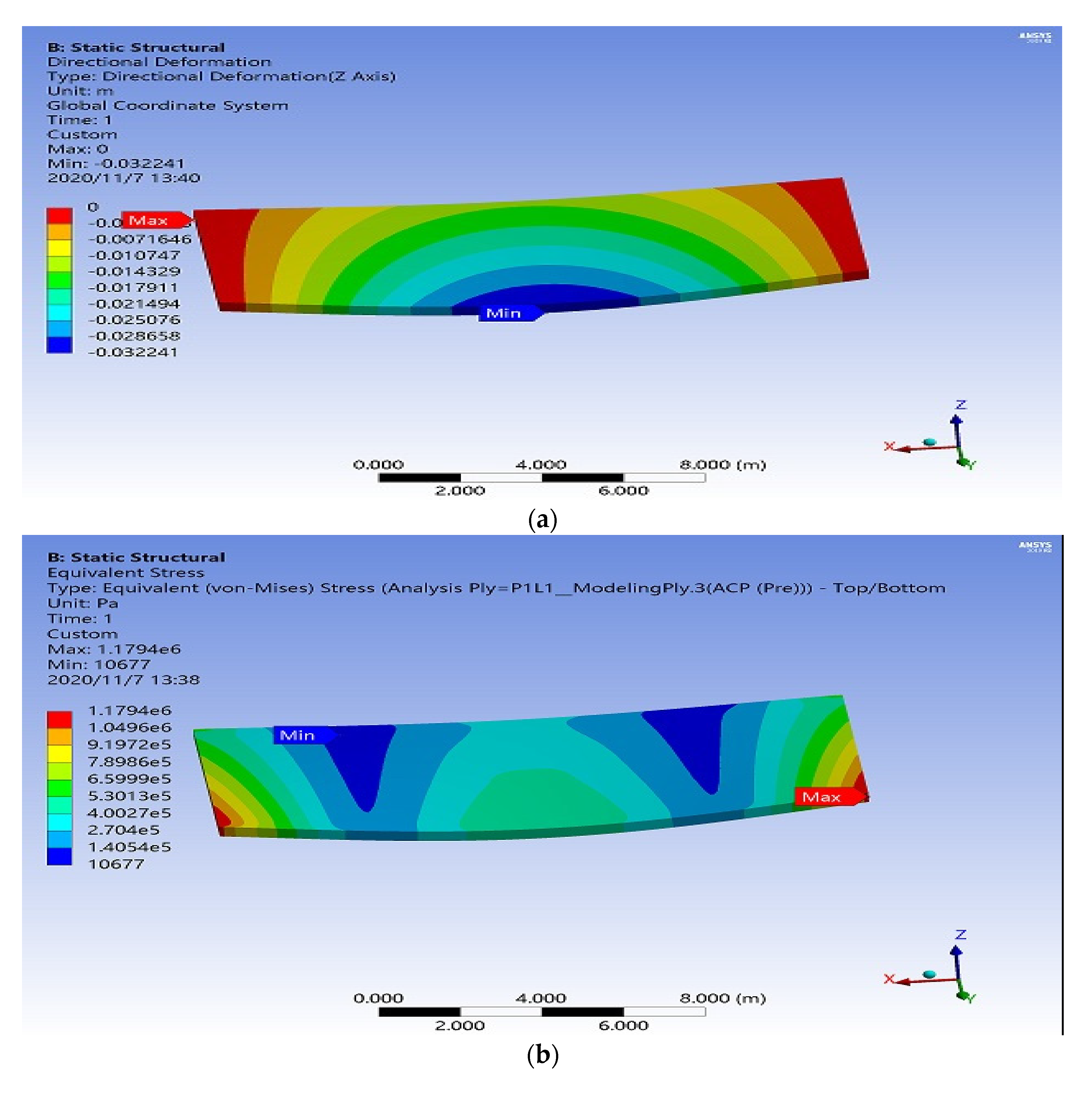
2.4. Finite Element Model of the Bridge Deck

The research in this article aims to find an appropriate model for a bridge structure based on minimum mass and thickness, using natural wood and composite materials as a replacement for reinforced concrete and steel bridges. The total length and width of the bridge were taken at 16 m and 7.5 m, respectively. By fixing these both dimensions, work on different thicknesses was done. The selection of size is based on the previous study in which Balsa wood was used to design the bridge [27]. The model was created in ANSYS WORKBENCH using a geometric modeling tool for both ULS and SLS verifications. The layered shell element SHELL 181 was used in ANSYS WORKBENCH to develop the FEA model for global verification. Layered shell element has short computational time. It is easier to create the mesh in shell element, and also, it needs less disc space for results. Post-processing in the layered shell element type is also faster. In addition, shell elements have both translations as well as rotation degrees of freedom. The main disadvantage of the solid element is locking, in which the solid element shows the bending behavior much stiffer in comparison with an analytical solution. Layered SHELL 181 is ideal for the study of thin to medium dense shell systems. This is ideally adapted for linear, broad rotation, and wide non-linear strain applications. Throughout the domain components, both complete and reduced integration schemes are supported. Layered SHELL 181 accounts for the follower (load stiffness) effects of the distributed pressure. It is a four-node feature with six degrees of freedom at each node: transformations in x, y, and z directions, and rotations in all three axes. According to the ANSYS reference manual, layered shell 181 element can be used for layered applications for modeling composite thin to moderately thick shell or sandwich structures. The accuracy of the layered shell 181 element is based on the first-order shear deformation theory (FSDT) (usually referred to as Mindlin–Reissner shell theory). In [36,37] Vrabie, used the shell element to design the sandwich structure. Moreover, according to [20], layered shell elements can be used in this type of bridge for global verification. Therefore, in the present case, the layered shell element shell 181 is expected to predict results with sufficient accuracy. For the discretization of the model, element size 0.1 m was used. The FEA model of the bridge structure used in this research is shown in Figure 1.
PrePost (ACP) module for composites of the software was used to create a preliminary model of the composite lay-up using 0.001 m of thickness. While designing the lay-up in the ACP module, Rosettes and oriented selection sets were used for fiber orientation and directions. Composite plies were then created with the help of modeling groups. Orthotropic properties were used for both wood cores and FRP skins. Boundary conditions were then applied. Displacements in the X, Y, and Z directions were constrained on both ends of the bridge, as shown in Figure 1d. A total load of running traffic on the bridge was applied in two groups, one on each lane, loads of 4 × 90 kN and 4 × 135 kN with characteristic values were applied on lane 1 and 2, respectively. In lane 1 there was a car, and a 90 kN load was applied on each wheel. The position of the car was at the center of the bridge span. The distance between the front wheels was 2 m, and the distance between the front and rear wheel was 2.5 m. The loading area occupied by each wheel was 0.2 × 0.4 m2 shown in the four boxes on each lane, and 2.25 kN/m2 of the distributed load was additionally applied. This additional distributed load was applied at a breadth of 3.75 m and a length of 16 m. In lane 2 there was a mini truck, all the positions were the same except the load, which in this case was 135 kN, and also 8.1 kN/m2 of the additional distributed load was applied on 3.75 × 16 m2 of the area. Figure 1a,b show the distributed load on lanes 1 and 2 of the bridge structure, whereas Figure 1c,d show the vehicle’s position and boundary conditions, respectively. Parameterization for all desired parameters was performed in the respective modules of ACP Prepost and static structural.
The composite model of the bridge was designed in ACP module, then it was transferred to the Static Structural system for computing the values of safety factors and other parameters for the composite failure. The materials properties used are mentioned in Table 1 and Table 2. The calculation time was about 8 h for each simulation in which the results were checked by adding 40 mm core thicknesses and 1 mm for each angle of FRP material each time until the suitable value was achieved. The specifications of the workstation were Intel (R) Xeon (R) CPU E5-2620 V2 @ 2.10 GHz (24 CPU), 32 GB RAM, and 2 TB HD

2.5. Materials

The skin of the sandwich structure is composed of carbon/epoxy and glass/epoxy materials. The mechanical properties of these materials are shown in Table 1.
In the bridge sandwich structure, three different cores were used. The properties of the material used in the core are mentioned in Table 2.
Table 3 lists the content considerations applied at ULS and SLS conditions.

3. Results and Discussion

All the results obtained from FEA are listed in Table 4. For each wood core, there are four cases, two for ULS and two for SLS conditions. These four cases are based upon the outer skin of CFRP and GFRP materials. Every case was composed of two laminate angle formations. Materials used in the core are shown in the first column of the Table 4. Lay-up configuration for both desired angles is mentioned in the lay-up portion. The thickness section shows the minimum values of the thickness on which the bridge is safe from all kinds of failures, both the inner and outer thicknesses are written. Total deformation is mentioned in accordance with the span limit formula in the fourth section of the table. The results of the deflection were compared with the previous study, which are the same. Please see the SU concept in [27], where for 16 m, the deformation was less than 32 mm. Michael Osei-Antwi [27] used the design methodology, which was used for experimental work by Thomas [20]. In this case, the value of deformation was less than 32 mm in each configuration. This research was extended to find six other parameters besides deflection. Different failure criteria are mentioned in the fifth section, with the minimum values on which the bridge is in stable condition. Total mass for all model configurations is then calculated and written in the last section of the column.

3.1. Lay-up [45/−45]

For parametric optimization, three different types of woods were used as the core material. Cross-ply laminate [45/−45] is optimized for minimum mass and thickness on the same loading and boundary conditions. Starting from 1 mm thickness, the number of ply layers was varied to 48, and with the addition of each number, the thickness of 1 mm was increased for each ply angle to the total value. Seven different parameters were studied for the stability of the structure. Values of material constraints Tsai-Wu, Tsai-Hill, and MS should be greater than unity. The second is the deformation must be less than 32 mm according to the span limit relation span/500. All the results obtained from FEA are three are mentioned in Table 4 under ULS and SLS conditions.
For the Bamboo wood core, there were two cases for the CFRP. For ULS, the MS criterion, Tsai-Wu ( S F T W ) criterion, Tsai-Hill ( S F T H ) criterion and the core factor were 4.84, 4.75, 4.36, and 53.8, respectively, and were greater than 1. The fiber plies for skins were [ 45 10 / 45 10 ] 20 , which showed that the total number of fiber laminates was 20 on either side with a core thickness of 400 mm. The deformation was in the safe limit, and the value was −0.032 m equals to the maximum allowable value of −0.032 m. This configuration has 43,280 kg of the total mass. The values of Equivalent stress and Maximum shear stress were 5.40 MPa, and 2.83 MPa, which were lower compared to the value of tensile strength. So, the bridge was safe in this configuration. For the ULS condition with GFRP skin, the above-stated criteria were 7.77, 7.21, 7.01, and 77.5, respectively, with the lay-up of [ 45 11 / 45 11 ] 22 , and the core of 440 mm. However, the thickness and mass drastically increased to 484 mm and 50,266 kg, respectively. The deformation, in this case, was 0.028 m.
For the SLS conditions, the bamboo core and CFRP laminate skin, the MS criterion, Tsai-Wu ( S F T W ) and Tsai-Hill ( S F T H ) criteria and core factor were 11.26, 11.05, 10.14, and 56.59, respectively. The values of all the criteria mentioned above were greater than unity, and thus these values were suitable for our required configuration. We have also checked the values of equivalent, and maximum shear stresses, which in this case were 4.52 MPa and 2.34 MPa, respectively, and were lower than the yield strength of the core material. All seven parameters showed that the configuration [ 45 11 / 45 11 ] 22 , with the core of 440 mm, is safe for our model. The total deformation, in this case, was recorded as 0.024 m, with a total mass of 50,266 kg. When the skin was changed to GFRP, the values of these parameters were 14.99, 13.91, 13.49, and 72.69, respectively. However, the values of equivalent stress and maximum shear stress were increased to 4.46 MPa and 2.31 MPa, respectively. Deformation was increased to −0.028 m, with the same weight of 50,266 kg.
In the case of Paulownia with CFRP sheets under ULS conditions, the readings of MS, S F T W , S F T H , and CF are 2.95, 3.04, 2.95, and 23.43, respectively, for the thickness of [ 45 10 / 45 10 ] 20 . The values of equivalent stress and maximum shear stress were lower than Bamboo and equal to 3.75 MPa and 1.94 MPa, and it was less than tensile strength. The mass was reduced to 20,560 kg, for the same value of thickness as compared to the bamboo wood core. This showed that the Paulownia core is relatively better than the bamboo core. However, in this case, the value of deformation is −0.049 m, which is greater than 0.032 m, so its thickness must be increased to satisfy the criteria. In the case of Paulownia core GFRP face skin, the above-mentioned factors were 6.099, 6.22, 5.18, and 40.39, respectively. The deformation was recorded at −0.032 m. The thickness and overall mass were increased to 528 mm and 27,648 kg, respectively. The magnitudes of equivalent stress and maximum shear stress were increased to 2.66 MPa and 1.38 MPa, respectively.
When the Paulownia core was taken with CFRP laminate sheet under SLS conditions, the magnitudes of MS, S F T W , S F T H , and the core factor were 6.88, 7.10, 6.34, and 25.08, respectively. The magnitude of the core factor was greater as compared to other factors. The magnitudes of equivalent stress and maximum shear stress were 3.09 MPa and 1.6 MPa, respectively. Total deformation was increased to −0.038 m for this configuration, which does not satisfy the thickness criterion. When GFRP skin was used, the magnitudes of MS, S F T W , S F T H , and core factor were 11.74, 11.96, 9.97, and 37.81, respectively. The configuration of [ 45 12 / 45 12 ] 24 was obtained with a core thickness of 480 mm and an overall thickness of 528 mm, this thickness was greater than the CFRP case. The deformation enhanced to −0.035 m. Equivalent and maximum shear stresses were recorded as 2.66 MPa, and 1.38 MPa, respectively. These values were greater than CFRP face sheets. The total mass was recorded as 27,648 kg.
In the case of Balsa core with CFRP skin, the magnitudes for MS, S F T W , S F T H , and the core factor were 3.44, 3.68, 3.18, and 22.91, respectively. The configuration of [ 45 14 / 45 14 ] 28 was obtained, which showed 28 plies on each side were used with the total core thickness of 560 mm. The total thickness increased to the highest value of 616 mm as compared with the previous cases. In this case, 0.039 m of deformation was recorded. The value of equivalent stress and maximum shear stress is 0.61 MPa and 3.47 MPa, respectively, with a total mass of 26,768 kg. When GFRP skin was used, the magnitudes of the above-mentioned constraints were 4.28, 4.72, 3.67, and 26.40, respectively, with the same total mass of 26,768 kg. In this configuration, the bridge’s thickness is highest and equals 616 mm with a core thickness of 560 mm. The values of equivalent stresses and maximum shear stresses were 0.6 MPa and 0.35 MPa, respectively.
In the case of CFRP skin and Balsa core under SLS conditions, the magnitudes of MS, S F T W , S F T H , and the core factor were 6.61, 7.08, 6.11, and 22.64, respectively, on the total thickness of 616 mm. In this case, the ply thickness was recorded as 28 mm on either side, and the total weight recorded was 26,768 kg. The value of deformation was −0.039 m; also, equivalent stress and maximum shear stress were recorded as 0.61 MPa and 0.34 MPa, respectively. By using GFRP skin, the values for this configuration were 8.25, 9.08, 7.07, and 26.09, respectively. The deformation was also high, and its value was −0.048 m. The values of equivalent stresses and maximum shear stresses were almost the same as for the CFRP case.

3.2. Lay-Up [0/90]

Then the configuration of angle was changed to [0/90], and all the calculations were repeated, and it was shown that significant changes could occur due to the change in angle. For Bamboo wood core and CFRP skin under ULS conditions. The magnitudes for MS, Tsai-Wu ( S F T W ), Tsai-Hill ( S F T H ), and the core factor criterion were 9.92, 9.94, 9.92, and 35.9, respectively. All these factors were increased as compared to the [45/−45] configuration except the core factor. The laminate plies for inner and outer skins were [ 0 10 / 90 10 ] 20 , with a core thickness of 400 mm. The total mass for this configuration was 43,280 kg. The value of equivalent stress and maximum shear stress was 2.25 MPa and 1.17 MPa, respectively, with total deformation of −0.025 mm. In the case of GFRP skin, the values of the above-mentioned parameters are 7.94, 7.92, 7.94, and 56.2, respectively. The plies for laminate are [ 0 11 / 90 11 ] 22 for the inner and outer skin. The core and total thickness were 440 mm and 484 mm, respectively. The deformation, in this case, was recorded as −0.026 m. The values of equivalent stress and maximum shear stress were 3.07 MPa and 1.59 MPa, respectively. Total bridge thickness was increased as compared to CFRP laminates.
When CFRP skin was used with Bamboo core, under SLS conditions, the magnitudes for the MS, Tsai-Wu ( S F T W ), Tsai-Hill ( S F T H ) and the core factor were 19.07, 19.10, 19.07, and 33.72, respectively. The value of deformation was −0.025 m. The number of layers in this case was [ 0 10 / 90 10 ] 20 , with a core and a total thickness of 400 mm and 440 mm, respectively. For the same conditions, there were 22 layers for each side on this angle configuration [ 45 11 / 45 11 ] 22 with a core thickness of 440 mm and a total thickness of 484 mm. This showed that the ply angles have a significant effect on the results. Magnitudes of equivalent stress and maximum shear stress were decreased to 2.25 MPa and 1.17 MPa, respectively, but the overall mass was decreased to 43,280 kg. In the case of GFRP, the values of MS, S F T W , S F T H , and core factor were 15.32, 15.27, 15.31, and 52.72, respectively, with an overall thickness of 484 mm. Magnitudes of deformation, equivalent stress, and maximum shear stress were decreased to −0.026 m, 3.07 MPa, and 1.59 MPa, respectively.
When Paulownia core and CFRP skin was used, under ULS conditions, the magnitudes of MS, S F T W , S F T H , and core factors were 8.17, 8.47, 8.13, and 24.28, respectively. Core thickness was minimum, and its value was 400 mm. The magnitude of equivalent stress was 1.17 MPa, which is smaller than the [45/−45] alignment. However, the overall mass was decreased to 20,560 kg because the magnitude of thickness was decreased. In the case of GFRP skin, the magnitudes of MS, S F T W , S F T H ,   the core factor were 7.07, 7.07, 7.08, and 34.73, respectively. The total thickness was greater than the CFRP configuration, and the value was equal to 528 mm, with a core thickness of 480 mm. Deformation was reduced to −0.030 mm, it was −0.035 mm for the [45/−45] skin configuration. The magnitudes of equivalent stress and maximum shear stress were 1.51 MPa and 0.79 MPa, respectively.
In the case of CFRP skin and Paulownia core, under SLS conditions, the magnitudes of MS, S F T W , S F T H , and the core factor were 19.05, 19.87, 18.93, and 25.39, respectively. The deformation was decreased to −0.024 m, as it was −0.038 m, for the [45/−45] configuration. The overall thickness was boosted to 484 mm. Values of equivalent stress and shear stress became small. The weight obtained in this configuration was 22,616 kg. When the GFRP skin was used, the magnitudes of the above-mentioned parameters became 13.64, 13.64, 13.64, and 35.52, respectively. The overall thickness was increased to 528 mm. Deformation was increased to the value of −0.030 m. The values of equivalent stress and maximum shear stress was calculated as 1.5 MPa and 0.79 MPa, respectively.
In the case of CFRP skin and Balsa core, under ULS conditions, the magnitudes of MS, S F T W , S F T H , and the core factor were 9.51, 11.12, 9.46, and 30.79, respectively. All the values were perfect, with a deformation of −0.029 m and a total weight of 22,944 kg with a total thickness of 528 mm. By using GFRP skin, the magnitudes of the parameters were less than CFRP laminate, and their values were 7.37, 7.38, 7.37, and 33.69, respectively. The value of mass was recorded at 26,768 kg. Deformation, equivalent stress, and maximum shear stress values were also increased to −0.034 m, 0.38 MPa, and 0.22 MPa, respectively.
In the case of CFRP skin with Balsa core, under SLS conditions, the magnitudes for MS, S F T W , S F T H , and the core factor were 18.26, 21.37, 18.16, and 30.44, respectively. The total thickness was increased to the value of 528 mm with a CFRP thickness of 24 mm on each side. Deformation, equivalent stress, and maximum shear stress were decreased. By using GFRP skin, the magnitudes of the above-mentioned parameters are 14.21, 14.24, 14.21, and 33.29, respectively. The value of overall thickness was increased to 616 mm, and the total mass reaches to 26,768 kg. Magnitudes of deformation, equivalent stress, and maximum shear stress are −0.034 m, 0.38 MPa, and 0.22 MPa, respectively.

3.3. Best Bridge Configuration

Based on the results obtained from simulations, Paulownia has the best configuration for minimum weight and thickness. If angle configuration is considered, then [ 0 / 90 ] has the best results and can achieve the minimum level of deformation in almost all simulations, and if the composite layers are considered, then CFRP layers shows the best results for strength and weight. So, this configuration [ 0 10 / 90 10 ] 20 shows the minimum weight and thickness of 20,560 kg and 440 mm, respectively. All the parameters show excellent values of safety factors and stresses under desired loadings. Values for the best case are mentioned in Table 5 on each level of thickness.
Figure 2a shows the final values of directional deformation for the Paulownia core. Red color shows the place where the values were maximum. The value was minimum at the middle side of the bridge. Figure 2b shows the values of equivalent stress, the minimum value of 10,667 Pa was recorded on the entire surface, and a maximum value of 1.17 MPa was noticed on the corner sides of the bridge. Figure 2c shows the values of maximum shear stress, 0.62 MPa was recorded on the side corners of the bridge. Figure 2d shows the value safety factor S F T H for Paulownia core, and it is safe for all the values greater than 1. Figure 2e shows the values of a safety factor S F T W .

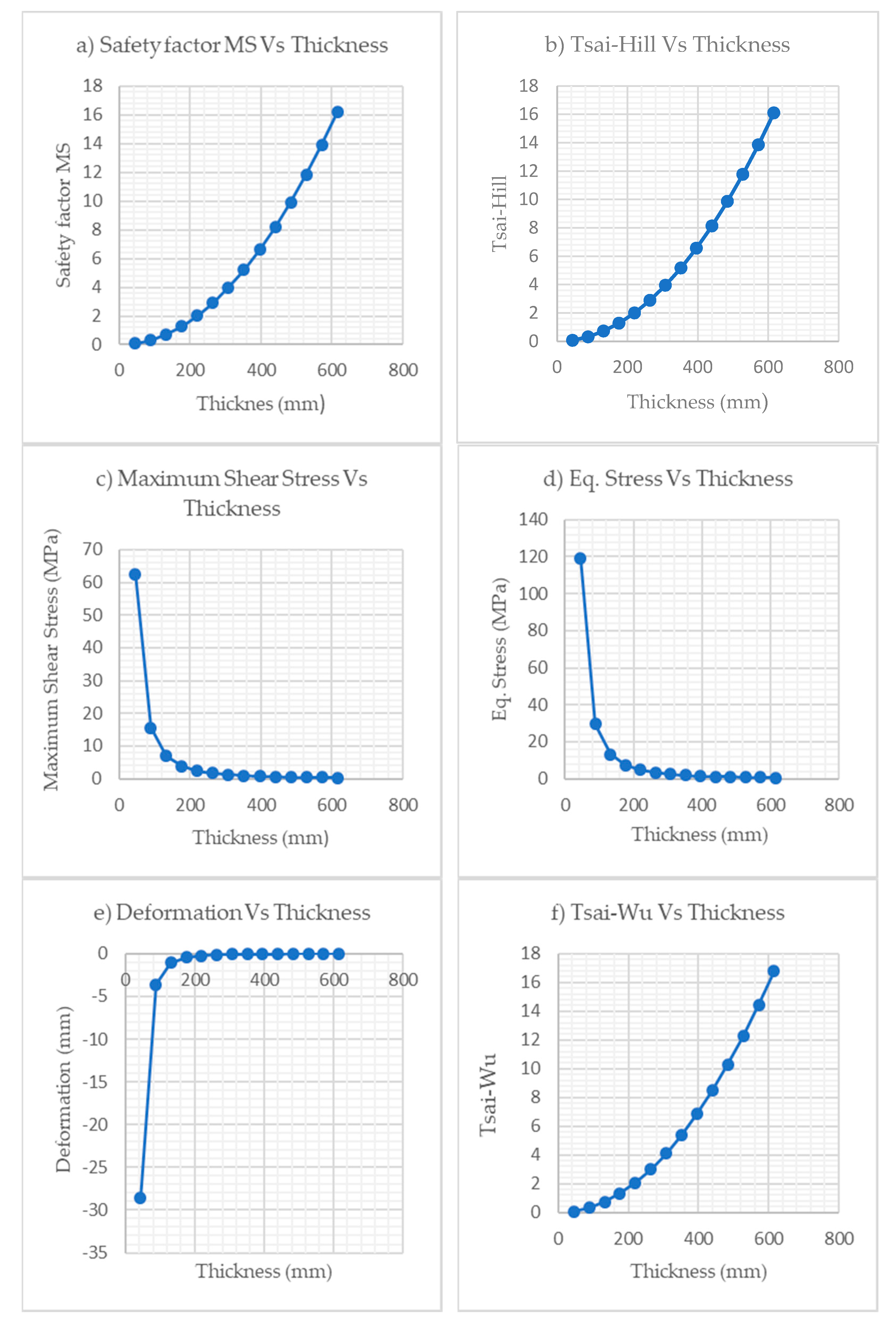
4. Graphical Evaluation and Comparison

Based on increasing thickness, graphs of all the parameters are plotted, as shown in Figure 3. The lay-up [ 45 10 / 45 10 ] 20 for the Paulownia core was selected as the best configuration bridge option. For this configuration, there were a total of 40 layers, 20 on either side. Figure 3a–e shows the graphs of all parameters against their thickness.
Figure 3 shows the effect of increasing length on Design Variables. Total thickness was varied from 44 mm to 616 mm, and the values of different factors were observed. In Figure 3a, when the thickness reached 176 mm, the value of safety factor MS becomes 1, this meant beyond 176 mm all the configurations were safe for safety factor MS. Tsai-Hill is the material constraint, and Figure 3b shows that the value started from 0.07 when the thickness was 44 mm, after that, it gradually increased with thickness and finally became 1 at 176 mm. The graph of Figure 3c comprises three main zones. The values went down more quickly in the first zone. The second zone was between the thickness of 120 mm to 280 mm; the values of the parameters went parallel to the axis in the third zone and the end at the minimum value of 0.32 MPa.
Figure 3d shows the equivalent stress, and its value was 118.97 MPa when the thickness was 44 mm. At 132 mm thickness, the value dropped down to 13.05 MPa, and then the trend became parallel to the axis and then finally ended at 0.61 MPa. Figure 3e shows the total deformation, which must be less than 0.032 m. The minimum value to fulfill the criteria was at the thickness of 440 mm. At this point, its value was −0.032 m. Beyond this value, all the configurations are safe, and for our final thickness, the value drops down to −0.012 m. Material constraint Tsai-Wu became 1 at 176 mm thickness in Figure 3f. At a 440 mm thickness, the final value was 16.78. Figure 3g determines the safety of the core, and thus it is known as the core factor. The value was 1 from the starting thickness and became 35.68 at 616 mm thickness. The deformation results obtained from the current research work were compared with the bridge used in a previous study [27].

5. Conclusions

A composite sandwich structure bridge with wood core was designed based on the minimum thickness and mass. Three different types of woods were used as the core material of the structure. CFRP and GFRP materials were used with two different angle configurations as the skin material of the structure. The FEA model of the bridge was designed in an ACP module with two lanes and two vehicles. Then it was transferred to the static structural system for computing the values of safety factor and other parameters under ULS and SLS conditions. It was concluded that the bridge structure’s design and strength greatly depend on the core’s fiber orientation and material. After examining the overall results, we concluded that Paulownia wood with [ 0 10 / 90 10 ] 20 configuration and CFRP layers are the best configurations for minimum weight and thickness. The magnitudes of MS, S F T W , S F T H , and core factor were recorded 8.17, 8.47, 8.13, and 24.28, respectively. Overall thickness was attained 440 mm with a total mass of 20,560 kg. The values of Equivalent and shear stresses were 1.17 and 0.62 MPa, respectively. Deflection for this case was recorded 32 mm.

Author Contributions

Conceptualization, H.M.W. and D.S.; Data curation, H.M.W. and S.Z.K.; Formal analysis, H.M.W. and S.Z.K.; Funding acquisition, D.S.; Investigation, H.M.W.; Methodology, H.M.W.; Project administration, D.S.; Resources, D.S.; Software, M.I.; Supervision, D.S. and L.T.; Validation, M.I. and S.R.Q.; Visualization; W.A.; Writing—original draft. All authors have read and agreed to the published version of the manuscript.

Funding

This work is funded by the National Natural Science Foundation of China, ‘Study on the characteristic of motion and load of bubbles near a solid boundary in shear flows’ grant number (51679056) and Natural Science Foundation of Heilongjiang Province of China (E2016024).

Conflicts of Interest

The authors declare no conflict of interest.

References

  1. Gao, T.; Cho, J.-U. A study on damage and penetration behaviour of carbon fiber reinforced plastic sandwich at various impacts. Int. J. Precis. Eng. Manuf. 2015, 16, 1845–1850. [Google Scholar] [CrossRef]
  2. Fotsing, E.R.; Leclerc, C.; Sola, M.; Ross, A.; Ruiz, E. Mechanical properties of composite sandwich structures with core or face sheet discontinuities. Compos. Part B Eng. 2016, 88, 229–239. [Google Scholar] [CrossRef]
  3. Yan, L.; Kasal, B.; Huang, L. A review of recent research on the use of cellulosic fibres, their fibre fabric reinforced cementitious, geo-polymer and polymer composites in civil engineering. Compos. Part B Eng. 2016, 92, 94–132. [Google Scholar] [CrossRef]
  4. Javaid, U.; Khan, Z.M.; Khan, M.B.; Bassyouni, M.; Abdel-Hamid, S.M.-S.; Abdel-Aziz, M.H.; ul Hasan, S.W. Fabrication and thermo-mechanical characterization of glass fiber/vinyl ester wind turbine rotor blade. Compos. Part B Eng. 2016, 91, 257–266. [Google Scholar] [CrossRef]
  5. Jayaseelan, D.D.; Xin, Y.; Vandeperre, L.; Brown, P.; Lee, W.E. Development of multi-layered thermal protection system (TPS) for aerospace applications. Compos. Part B Eng. 2015, 79, 392–405. [Google Scholar] [CrossRef]
  6. Wu, H.-C.; Yan, A. Durability simulation of FRP bridge decks subject to weathering. Compos. Part B Eng. 2013, 51, 162–168. [Google Scholar] [CrossRef]
  7. Wang, C.; Shankar, K.; Morozov, E.V. Global design and analysis of deep sea FRP composite risers under combined environmental loads. Adv. Compos. Mater. 2017, 26, 79–98. [Google Scholar] [CrossRef]
  8. Imran, M.; Shi, D.; Tong, L.; Muhammad, H. Design optimization of composite submerged cylindrical pressure hull using genetic algorithm and finite element analysis. Materials 2019, 190, 145. [Google Scholar] [CrossRef]
  9. ASTM. Standard Terminology of Structural Sandwich Constructions; ASTM International: West Conshohocken, PA, USA, 1999. [Google Scholar]
  10. Yang, G.; Shi, Z.; Mo, N.; Zhao, L. Research on active magnetic bearing applied in Chinese modular high-temperature gas-cooled reactor. Prog. Nucl. Energy 2014, 77, 352–360. [Google Scholar] [CrossRef]
  11. Abrate, S.; Castanié, B.; Yapa, D.S.R. Dynamic Failure of Composite and Sandwich Structures; Springer: Berlin/Heidelberg, Germany, 2013; ISBN 978-94-007-5329-7. [Google Scholar]
  12. Waqas, M.H.; Shi, D.; Imran, M.; Khan, S.Z.; Tong, L.; Ahad, F.; Zaidi, A.A.; Iqbal, J.; Ahmed, W. Conceptual Design of Composite Sandwich Structure Submarine Radome. Materials 2019, 12, 1966. [Google Scholar] [CrossRef] [Green Version]
  13. Ferdous, W.; Manalo, A.; Aravinthan, T.; Fam, A. Flexural and shear behaviour of layered sandwich beams. Constr. Build. Mater. 2018, 173, 429–442. [Google Scholar] [CrossRef]
  14. Tomlinson, D.; Fam, A. Flexural behavior of precast concrete sandwich wall panels with basalt FRP and steel reinforcement. PCI J. 2015. [Google Scholar] [CrossRef]
  15. CoDyre, L.; Mak, K.; Fam, A. Flexural and axial behaviour of sandwich panels with bio-based flax fibre-reinforced polymer skins and various foam core densities. J. Sandw. Struct. Mater. 2018, 20, 595–616. [Google Scholar] [CrossRef]
  16. Keller, T. Recent all-composite and hybrid fibre-reinforced polymer bridges and buildings. Prog. Struct. Eng. Mater. 2001, 3, 132–140. [Google Scholar] [CrossRef]
  17. Zureick, A. Fiber Reinforced Polymeric Bridge Decks. Struct. Eng. Rev. 1995, 7, 257–266. [Google Scholar]
  18. Kim, Y.J. State of the practice of FRP composites in highway bridges. Eng. Struct. 2019, 179, 1–8. [Google Scholar] [CrossRef]
  19. Robinson, M.J.; Kosmatka, J.B. Lightweight fiber-reinforced polymer composite deck panels for extreme applications. J. Compos. Constr. 2008, 12, 344–354. [Google Scholar] [CrossRef]
  20. Keller, T.; Rothe, J.; de Castro, J.; Osei-Antwi, M. GFRP-balsa sandwich bridge deck concept, design and experimental validation. J. Compos. Constr. 2013, 18, 04013043. [Google Scholar] [CrossRef]
  21. Nair, A.; Cai, C.S.; Kong, X.; Hou, S. Bridge Retrofitting Using FRP-Wrapped Balsa Wood Deck: Experimental Study and Field Evaluation. J. Aerosp. Eng. 2019, 32, 04019065. [Google Scholar] [CrossRef]
  22. Kulpa, M.; Siwowski, T. Stiffness and strength evaluation of a novel FRP sandwich panel for bridge redecking. Compos. Part B 2019, 167, 207–220. [Google Scholar] [CrossRef]
  23. Li, Z.; He, M.; Tao, D.; Li, M. Experimental buckling performance of scrimber composite columns under axial compression. Compos. Part B Eng. 2015, 86, 203–213. [Google Scholar] [CrossRef]
  24. Gilfillan, R.; Gilbert, S.; Patrick, G. The improved performance of home-grown timber glulam beams using fibre reinforcement. J. Inst. Wood Sci. 2001, 15, 307–317. [Google Scholar]
  25. Buell, T.W.; Saadatmanesh, H. Strengthening timber bridge beams using carbon fiber. J. Struct. Eng. 2005, 131, 173–187. [Google Scholar] [CrossRef]
  26. Bascule FRP Composite Footbridge FIRECO, Client: Vaerste AS and Fredrikstad Commune, Design: Griff kommunikasjon. Available online: http://.fireco.no/wp-content/uploads/2019/03/Gangbru-Vesterelven.pdf (accessed on 15 February 2020).
  27. Osei-Antwi, M.; de Castro, J.; Vassilopoulos, A.P.; Keller, T. Structural limits of FRP-balsa sandwich decks in bridge construction. Compos. Part B 2014, 63, 77–84. [Google Scholar] [CrossRef]
  28. Orifici, A.C.; Herszberg, I.; Thomson, R.S. Review of methodologies for composite material modelling incorporating failure. Compos. Struct. 2008, 86, 194–210. [Google Scholar] [CrossRef]
  29. Barbero, E.J. Finite Element Analysis of Composite Materials Using Abaqus, 1st ed.; CRC Press Taylor nd Francis Group: Boca Raton, FL, USA, 2013. [Google Scholar]
  30. Lopez, R.H.; Miguel, L.F.F.; Belo, I.M.; Cursi, J.E.S. Advantages of employing a full characterization method over FORM in the reliability analysis of laminated composite plates. Compos. Struct. 2014, 107, 635–642. [Google Scholar] [CrossRef]
  31. Kaw, A.K. Mechanics of Composite Materials, 2nd ed.; Mechanical and Aerospace Engineering Series; CRC Press: Boca Raton, FL, USA, 2005. [Google Scholar]
  32. The European Union. Eurocode: BS EN 1990:2002+A1:2005 Basics of Structural Design; The European Union: Brussels, Belgium, 2005. [Google Scholar]
  33. Empfehlung, B. Tragende Kuststoffbauteile im Bauwesen—Entwurf, Bemessung und Konstruktion; Bau-Überwachungsverein: Berlin, Germany, 2010. [Google Scholar]
  34. Clarke, J.L. Structural Design of Polymer Composites—Eurocomp Design Code and Handbook; E & FN Spon: London, UK, 1996. [Google Scholar]
  35. European Standard. Eurocode 2-Part 2. Design of Concrete Structures: Concrete Bridges-Design and Detailing Rules; European Committee for Standardization: Brussels, Belgium, 2005. [Google Scholar]
  36. Thai, H.-T.; Choi, D.-H. A simple first-order shear deformation theory for laminated composite plates. Compos. Struct. 2013, 106, 754–763. [Google Scholar] [CrossRef]
  37. Radu Chiriac and Mihai Vrabie. The First Order Shear Deformation Theory for Coposite Plates. Intersections 2016, 13, 37–47. [Google Scholar]
  38. ANSYS. Engineering Data; Composite Materials Library; ANSYS: Canonsburg, PA, USA, 2017. [Google Scholar]
  39. Fang, H.; Sun, H.; Liu, W.; Wang, L.; Bai, Y.; Hui, D. Mechanical performance of innovative GFRP-bamboo-wood sandwich beams: Experimental and modelling investigation. Compos. Part B Eng. 2015, 79, 182–196. [Google Scholar] [CrossRef]
  40. De Osei-Antwi, M. Structural Performance of Complex Core Systems for FRP-balsa Composite Sandwich Bridge Decks; École Polytechnique Fédérale De Lausanne: Lausanne, Switzerland, 2014. [Google Scholar]
  41. Green, D.E.; Winandy, J.E.; Kretschmann, D.E. Mechanical Properties of Wood. Wood Handbook: Wood as an Engineering Material; Forest Products Laboratory: Madison, WI, USA, 1999. [Google Scholar]
  42. Lei, Y.; Zhang, J.; Chen, Z.; Song, X.; Huang, Z.; Xiao, J. Mechanical properties of mulberry branch reconstituted square lumber. BioResources 2017, 12, 5838–5850. [Google Scholar] [CrossRef] [Green Version]
  43. Eric, M. The Wood Database. Available online: https://www.wood-database.com/ (accessed on 18 May 2019).
  44. Shanmugasundaram, N.; Rajendran, I. Characterization of raw and alkali-treated mulberry fibers as potential reinforcement in polymer composites. J. Reinf. Plast. Compos. 2016, 35, 601–614. [Google Scholar] [CrossRef]
  45. European Standard. Eurocode 5-Part 1. Design of Timber Structures: General Common Rules and Rules for Building; European Committee for Standardization: Brussels, Belgium, 2005. [Google Scholar]
Figure 1. (a) Distributed load on lane 1 (b) Distributed load on lane 2; (c) Position of vehicles on the lane; (d) Boundary conditions.
Applsci 11 00214 g001aApplsci 11 00214 g001b
Figure 2. (a) Directional deformation; (b) Equivalent stress; (c) Maximum shear stress; (d) Tsai-Hill safety factor; (e) Tsai-Wu safety factor.
Applsci 11 00214 g002aApplsci 11 00214 g002b
Figure 3. (a) Safety factor MS vs. thickness; (b) Safety factor Tsai-Hill vs. thickness; (c) Max. shear stress vs. thickness; (d) Eq. stress vs. thickness; (e) Directional deformation vs. thickness. (f) Safety factor Tsai-Wu vs. thickness (g) Core factor vs. thickness.
Applsci 11 00214 g003aApplsci 11 00214 g003b
Table 1. Properties of glass/epoxy and carbon/epoxy [38].
Mechanical PropertiesGlass/EpoxyCarbon/Epoxy
Elastic Modulus
E 1 (MPa)45,000121,000
E 2 (MPa)10,0008600
E 3 (MPa)10,0008600
Shear Modulus
G 12 (MPa)50004700
G 13 (MPa)50004700
G 23 (MPa)3846.23100
Density ( kg / m 3 ) 20001490
Poisson Ratio
Nu 12 0.30.27
Nu 13 0.30.27
Nu 23 0.40.40
Tensile Strength
TS 1 (MPa)11002231
TS 2 (MPa)3529
TS 3 (MPa)3529
Table 2. Properties of materials used in the core of bridge [39,40,41,42,43,44].
Mechanical PropertiesPaulownia WoodBambooBalsa Wood
Elastic Modulus
E 1 (MPa)432010,000200
E 2 (MPa)147025004320
E 3 (MPa)14702500200
Shear Modulus
G 12 (MPa)294275354
G 13 (MPa)209275309
G 23 (MPa)29427564
Density ( kg / m 3 ) 280742250
Poisson Ratio
Nu 12 0.230.310.23
Nu 13 0.230.310.49
Nu 23 0.230.310.66
Tensile Strength(MPa)49.10128.5323.50
Table 3. Material factors used in the design.
Component and ActionFactor
ULSSLS
FRP laminates, traffic load a2.641.50
FRP laminates, permanent load a2.881.50
Balsa/timber b1.501.60
a Data from BÜV [33]. b Data from Euro code 5 part 1 [45].
Table 4. FEA Results for all bridge configurations under ULS and SLS conditions.
CoreMaterialLaminate Lay-Up Inner and Outer SkinInner Skin Thickness (mm)Outer Skin Thickness (mm)Core Thickness (mm)Total Thickness (mm)Deform- ation mmEq. Stress (MPa)Safety Factor (MS)Tsai-WuTsai-HillCore FactorMax. Shear Stress (MPa)Mass kg
Bamboo
ULS
CFRP [ 45 10 / 45 10 ] 20
[ 0 10 / 90 10 ] 20
2020400440−0.0325.404.844.754.3653.82.8343,280
2020400440−0.0252.259.929.949.9235.91.1743,280
Bamboo
ULS
GFRP [ 45 11 / 45 11 ] 22
[ 0 11 / 90 11 ] 22
2222440484−0.0284.467.777.217.0177.52.3150,266
2222440484−0.0263.077.947.927.9456.21.5950,266
Bamboo
SLS
CFRP [ 45 11 / 45 11 ] 22
[ 0 10 / 90 10 ] 20
2222440484−0.0244.5211.2611.0510.1456.592.3450,266
2020400440−0.0252.2519.0719.1019.0733.721.1743,280
Bamboo
SLS
GFRP [ 45 11 / 45 11 ] 22
[ 0 11 / 90 11 ] 22
2222440484−0.0284.4614.9913.9113.4972.692.3150,266
2222440484−0.0263.0715.3215.2715.3152.721.5950,266
Paulownia
ULS
CFRP [ 45 10 / 45 10 ] 20
[ 0 10 / 90 10 ] 20
2020400440−0.0493.752.953.042.9523.431.9420,560
2020400440−0.0321.178.178.478.1324.280.6220,560
Paulownia
ULS
GFRP [ 45 12 / 45 12 ] 24
[ 0 12 / 90 12 ] 24
2424480528−0.0352.666.0996.225.1840.391.3827,648
2424480528−0.0301.517.077.077.0834.730.7927,648
Paulownia
SLS
CFRP [ 45 11 / 45 11 ] 22
[ 0 11 / 90 11 ] 22
2222440484−0.0383.096.887.106.3425.081.622,616
2222440484−0.0240.9719.0519.8718.9325.390.5222,616
Paulownia
SLS
GFRP [ 45 12 / 45 12 ] 24
[ 0 12 / 90 12 ] 24
2424480528−0.0352.6611.7411.969.9737.811.382,7648
2424480528−0.0301.513.6413.6413.6435..520.792,7648
Balsa
ULS
CFRP [ 45 14 / 45 14 ] 28
[ 0 12 / 90 12 ] 24
2828560616−0.0390.613.443.683.1822.913.472,6768
2424480528−0.0290.369.5111.129.4630.790.2122,944
Balsa
ULS
GFRP [ 45 14 / 45 14 ] 28 [ 0 14 / 90 14 ] 28 2828560616−0.0480.64.284.723.6726.400.3526,768
2828560616−0.0340.387.377.387.3733.690.2226,768
Balsa
SLS
CFRP [ 45 14 / 45 14 ] 28
[ 0 12 / 90 12 ] 24
2828560616−0.0390.616.617.086.1122.640.3426,768
2424480528−0.0290.3618.2621.3718.1630.440.2122,944
Balsa
SLS
GFRP [ 45 14 / 45 14 ] 28
[ 0 14 / 90 14 ] 28
2828560616−0.0480.618.259.087.0726.090.3526,768
2828560616−0.0340.3814.2114.2414.2133.290.2226,768
CFRP—carbon fiber reinforced polymer, GFRP—glass fiber reinforced polymer.
Table 5. Results of the bridge structure with Paulownia core.
Ply1Ply2 CorePly1Ply2Safety Factor MS Safety   Factor   S F T H Max. Shear Stress (MPa)Eq. Stress
(MPa)
Directional Deformation Safety   Factor   S F T W Core Factor
1140110.080.0762.49118.97−28.610.081.07
2280220.320.3115.6629.66−3.590.333.07
33120330.720.726.9113.05−1.070.745.64
44160441.291.283.897.34−0.451.338.07
55200552.022.002.484.69−0.232.0810.61
66240662.912.891.723.25−0.133.0113.24
77280773.973.951.272.39−0.0884.1115.94
88320885.205.170.971.83−0.0605.3918.69
99360996.606.560.771.45−0.0436.8421.47
101040010108.178.130.621.18−0.0328.4724.28
111144011119.929.860.520.98−0.02410.2827.12
1212480121211.8411.770.440.83−0.01912.2729.96
1313520131313.9313.850.370.71−0.01514.4332.82
1414560141416.2016.100.320.61−0.01216.7835.68
Publisher’s Note: MDPI stays neutral with regard to jurisdictional claims in published maps and institutional affiliations.

