1. Introduction
Polycaprolactone (PCL) is a biodegradable semicrystalline poly(α-hydroxyester) that resorbs slowly by hydrolysis due to its high crystallinity and hydrophobic nature [
1,
2]. It is synthesized by ring-opening polymerization of ε-caprolactone. The material is semi-crystalline, its melting temperature is 59–64 °C, and its glass transition temperature is −60 °C. PCL is extremely hydrophobic, so it has longer degradation periods than polylactide, making it appropriate for applications requiring long degradation times. In the human body, PCL is resorbed via hydrolysis of the ester linkages. Thus, it has gained much attention as a material for implantable devices. The polymer has also found applications in many fields, such as implantable biomaterials, biodegradable scaffolds, and micro-/nano-particles for drug delivery [
3]. Various pharmaceuticals have been incorporated into PCL for drug delivery and targeted release. PCL scaffolds have also been developed for tissue engineering of bone and cartilage.
Additive manufacturing [
4,
5], which is also called 3D printing, is an easy and adaptable method for the fabrication of products of intricate geometry. The advantages of additive manufacturing include manufacturing options, short time to market, customization, and intricacy, making the process one of the most favored techniques. Through continuous deposition of filaments and layers, additive manufacturing provides a brand new method for product fabrication. The most commonly employed additive manufacturing method is called fused deposition modeling (FDM) [
6]. The process expels thermoplastic melts from a nozzle and lays them onto the developing product. The extrusion nozzle moves in the x and y directions to compose one material layer each time. The nozzle then shifts in the z direction in tiny consecutive steps to make a fresh layer. The moving of the extruding nozzle is controlled by a microprocessor to eventually form a three-dimensional product.
The additive manufacturing of pure PCL or filled PCL composites, however, remains as a challenge, mainly due to the restricted availability of PCL filaments for FDM manufacturing [
7,
8]. To overcome this limitation, various works have been done. Guerra and Ciurana [
9] developed a fused filament fabrication (FFF)-based printer for additive manufacturing of polycaprolactone stents. Jhao et al. [
10] investigated the morphology and mechanical properties of hydroxyapatite/PCL scaffolds fabricated by a self-developed melt differential FDM 3D printer. Hollander et al. [
11] employed FDM printing of PCL implants for the delivery of micronized indomethacin. Visscher et al. [
12] combined FDM with a salt leaching method to develop a 3D printed PCL scaffold with dual micro- and macro-porosity. Despite these efforts, all these works were based on the FDM method, which employs high-temperature extrusions during the manufacturing process. Such a polymer extrusion process poses some restrictions, particularly when the fabricated product is employed as a device for drug delivery. Compounding polymers with pharmaceuticals at high temperatures in the melt extrusion of an additive manufacturing process can destroy or deteriorate the drugs [
13].
This study proposed a novel method for additive manufacturing of PCL products using a solution extrusion layer-by-layer scheme. PCL materials and solvent were first mixed and expelled from a feeder equipped with a syringe and a dispensing tip (nozzle). The dispensing tip was controlled and moved by a computer and microprocessor. As soon as the solvent volatilized, the solution was driven from the dispensing tip, solidified, and was piled in continuous layers to make parts of desired geometries. A single factor experimental design was carried out to evaluate the influence of different processing parameters on the tensile properties of additive manufactured parts. After manufacturing, the strength of manufactured PCL specimens was determined by a tensile testing machine, and the morphology was evaluated by a projector microscope and a field emission scanning electron microscope (SEM). A differential scanning calorimeter (DSC) analysis was also done to investigate the thermal patterns of fabricated PCL parts.
2. Materials and Methods
2.1. Materials
The materials included PCL (molecular weight Mn: 80,000 Da) and dichloromethane (DCM). Both were purchased from Sigma-Aldrich (St. Louis, Mo, USA).
2.2. Empirical Setup
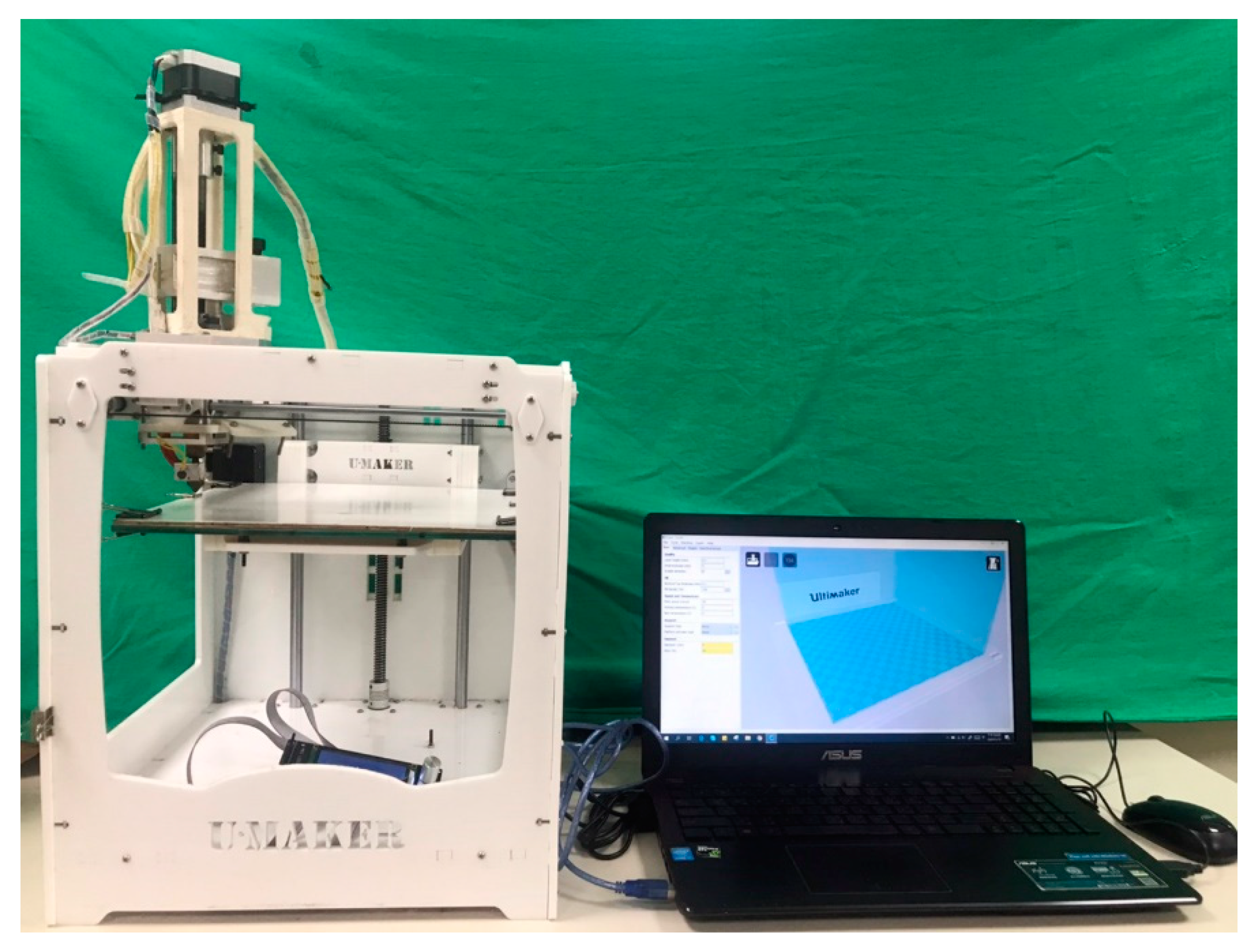
The solution extrusion additive manufacturing was done on a lab-developed fabrication device (
Figure 1). The device comprises a solution extrusion feeder, driving stepper motors and related components, a power source, a syringe, a dispensing tip with an inner diameter of 0.18 mm at the outlet (
Figure 2), an accumulation platform, and a user interface with connectivity. An open Cura interface (Ultimaker B.V., Geldermalsen, The Netherlands) was employed to manage the whole manufacturing procedure.
Figure 3 shows the entire extrusion manufacturing process. Predetermined weights of PCL pellets were first dissolved in DCM with various weight-to-volume ratios and mixed by a magnetic stirrer for 2 h. The solution was subsequently poured into the feeding system, which has a syringe and a plastic dispensing tip for manufacturing. During additive manufacturing, the feeder is prompted by a microprocessor-controlled servo motor and expels the PCL solution onto the collection platform from the dispensing tip. Through the vaporization of solvent, PCL strips of approximately 0.2 mm in width are deposited on the platform layer-by-layer; each layer has a thickness of approximately 0.10–0.15 mm.
2.3. Empirical Parameters
To estimate the influence of possible residual solvent on fabricated parts, a few specimens were first fabricated. The weights of the specimens were measured after placement in a ventilation chamber at room temperature (25 °C) for various periods of time (0–6 days). Five parameters were selected for the analysis: the PCL/DCM ratio, fill density, moving speed of the dispensing tip, and print orientation of infill of the extruded strips (
Figure 3C). Before the experiments, a few test trials were first completed to determine the range of processing parameters that can successfully manufacture the parts. The processable range was then subdivided so as to examine the influence of each factor on the fabricated part’s quality. The PCL/solvent (DCM) ratio (
w/
v) was 5 g/6.8 mL, 5 g/7.0 mL, 5 g/7.1 mL, or 5 g/7.2 mL. The fill density was 65%, 70%, 75%, or 80%. The moving speed of the dispensing tip ranged from 40 to 70 mm/s. The strips’ print orientation of infill was set as 30°, 45°, 75°, or 90° (see
Figure 3C).
Table 1 lists the parameters and parameter levels used in the experiments. The dispensing nozzle and the collection platform were not heated during the experimental procedure.
A geometry for tensile tests (
Figure 4A) was used to manufacture the part samples. A commercially available computer-aided design software (Solidworks, Waltham, MA, USA) was employed to produce the code for controlling the movement of the dispensing tip. After additive manufacturing, the mechanical properties of the manufactured dumbbell-shaped parts were evaluated using a tensile tester (Lloyd, Ameteck, Berwyn, PA, USA) with a 2500 N load cell by following the ASTM D638 standard. The tensile pulling speed was set as 60 mm/min. The tensile strength was computed as follows:
A full factorial experiment allows the investigator to investigate the effect of each factor on the response variable, as well as the effects of interactions between factors on the response variable. However, it requires a large number of samples and experimental trials, which is time-consuming. A single-factor experimental design utilizes experimental methodology to focus on only one subject. This design is distinct from case study methodology, which also focuses on one individual, because single-factor experimental designs use the same systematic processes as other experimental designs. The investigator establishes the study to manipulate an independent variable (or variables) and to measure how a dependent variable responds to changes in the independent variable. This design has the experimental benefit of a controlled comparison, because the individual subject serves as the control by engaging in all of the conditions [
14]. In this study, the single-factor experimental design was employed, where a set of arbitrarily selected processing condition (Level 2 in
Table 1) was selected as a reference. By altering one of the parameters each time while keeping the others unchanged, we were able to study the influence of every parameter on the mechanical properties of the parts. Five sample tests were completed for each trial.
2.4. Microscopic Observations
The morphology of the additively manufactured parts was observed under a profile projector (APEX-2010, Taipei, Taiwan) and a field emission scanning electron microscope (FESEM) (JEOL Model JSM-7500F, Tokyo, Japan).
2.5. Thermal Analysis
A differential scanning calorimeter (Model DSC25, TA Instruments, New Castle, DE, USA) was used to characterize the thermal properties of the PCL pellets and the additively manufactured PCL specimens. The scan temperature was between 30 and 90 °C, and the heating speed of the samples was set as 10 °C/min. For comparison, the thermal profiles of the parts were also characterized after annealing them in an oven at 50 °C for 1 h.
3. Results
PCL parts were successfully fabricated using the solution extrusion additive manufacturing device. The measured parts’ weight and length variations at 0–6 days post-manufacturing are shown in
Table 2. The weight and size decreased, which predominately resulted from the evaporation of the remaining solvents in the fabricated samples. The weight decrease and sample shrinkage became stable at 2 days post-manufacture, and the final weight and size decreased by about 4.23% and 13.8%, respectively. Other than the dimensional shrinkage, no warpage or distortion of manufactured parts was observed (see the sample before the tensile test in
Figure 4B).
3.1. Effects of Processing Parameters on Part Strength
Figure 5A shows the stress–strain curves of parts prepared using different PCL/DCM ratios, while
Figure 5B shows the maximum tensile strengths. The elongation at break generally increased with the volume of DCM. The maximum tensile strengths also increased as the volume of DCM increased. Parts manufactured using a ratio of 5 g/7.2 mL exhibited the greatest tensile strength, while fabricated parts with a ratio of 5 g/6.8 mL showed the worst mechanical properties.
Figure 9 shows the surface images of manufactured parts. Incompletely sealed orifices can be seen on surfaces of the solution extrusion manufactured products in the profile projector image. Small orifices were observed on the part surface, which mainly resulted from the evaporation of solvent. Better healing is observed in
Figure 9A (5 g/7.2 mL) than in
Figure 9B (5 g/6.8 mL), not only in the same layer but also across layers. Since the part made with the 5 g/6.8 mL solution showed greater pore sizes than parts made with 5 g/7.2 mL, it shows worse mechanical properties.
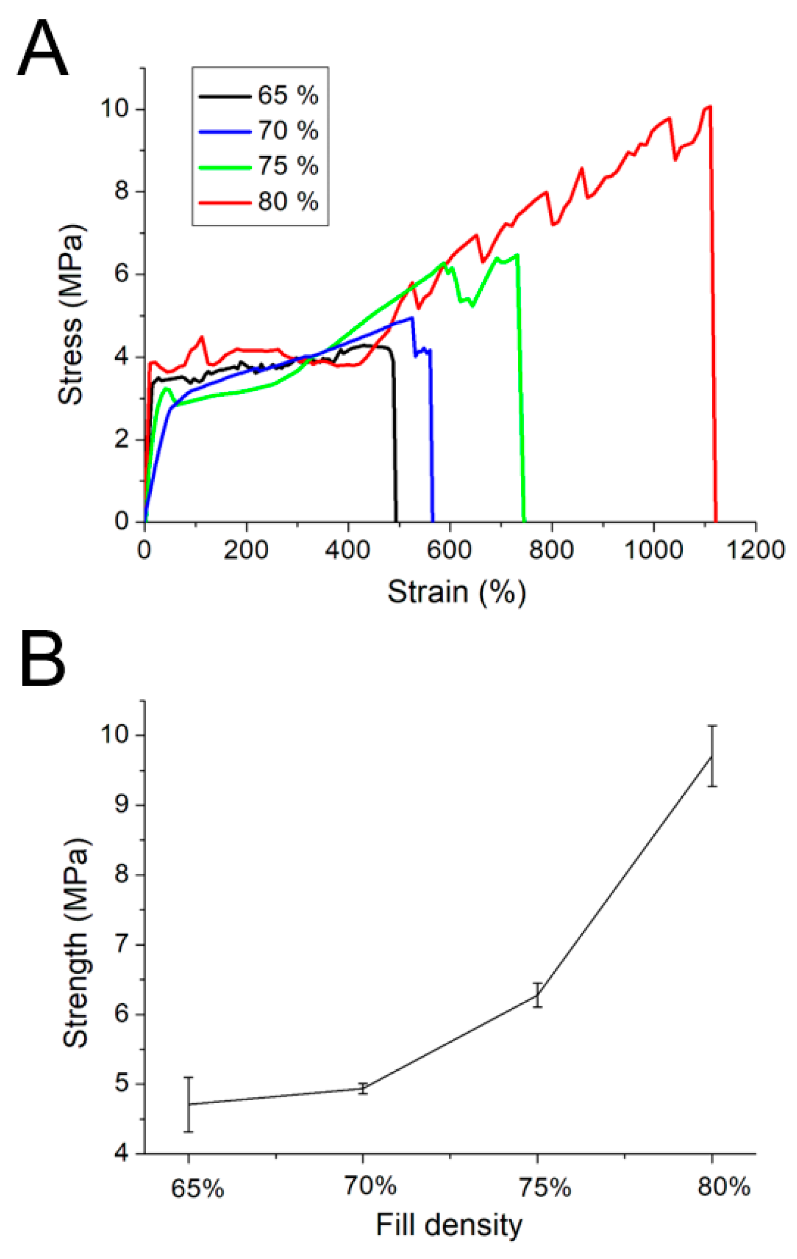
Figure 6A shows the stress–strain curves of parts manufactured using different fill densities. Clearly, the maximum strength and elongation at break increased with the fill density.
Figure 6B shows the influence of fill density on the maximum tensile strength of the fabricated parts. Parts with 80% fill density exhibited the greatest tensile strength, while parts fabricated with 65% exhibited the lowest mechanical properties.
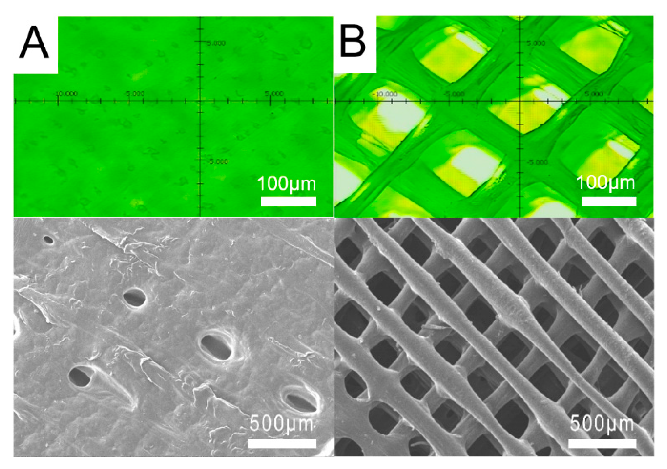
Figure 10A,B show the surface images of parts manufactured with 80% and 65% fill density, respectively. The surface of parts manufactured with 80% fill density are almost completely healed, but huge pores could still be seen on the surface of parts prepared with 65% fill density. Parts manufactured with a lower fill density showed larger pores, which may lead to stress concentrations during the tensile tests. Thus, they demonstrated lower mechanical strength.
Figure 7A shows the tensile test curves of parts manufactured with various speeds of the dispensing tip.
Figure 7B shows the effect of the tip’s moving speed on the maximum tensile strength. The tensile strength decreased generally with the tip’s speed. Parts prepared using a speed of 40 mm/s exhibited the greatest tensile strength, while parts fabricated with a speed of 70 mm/s showed the lowest mechanical properties.
Figure 11A,B show the surface images of parts manufactured using tip speeds of 40 mm/s and 70 mm/s, respectively. Again, all parts exhibit a fused surface with many incompletely healed small pores. Furthermore, parts manufactured with a tip speed of 70 mm/s showed pores of greater size than those fabricated with a tip speed of 40 mm/s. Thus, they showed worse mechanical properties.
Figure 8A shows the stress–strain curves of parts manufactured using different orientations of 30°, 45°, 75°, and 90°, and
Figure 8B shows the maximum tensile strength of these samples. The specimen manufactured with an orientation of 90° showed the greatest tensile strength, while 45° resulted in the lowest mechanical properties.
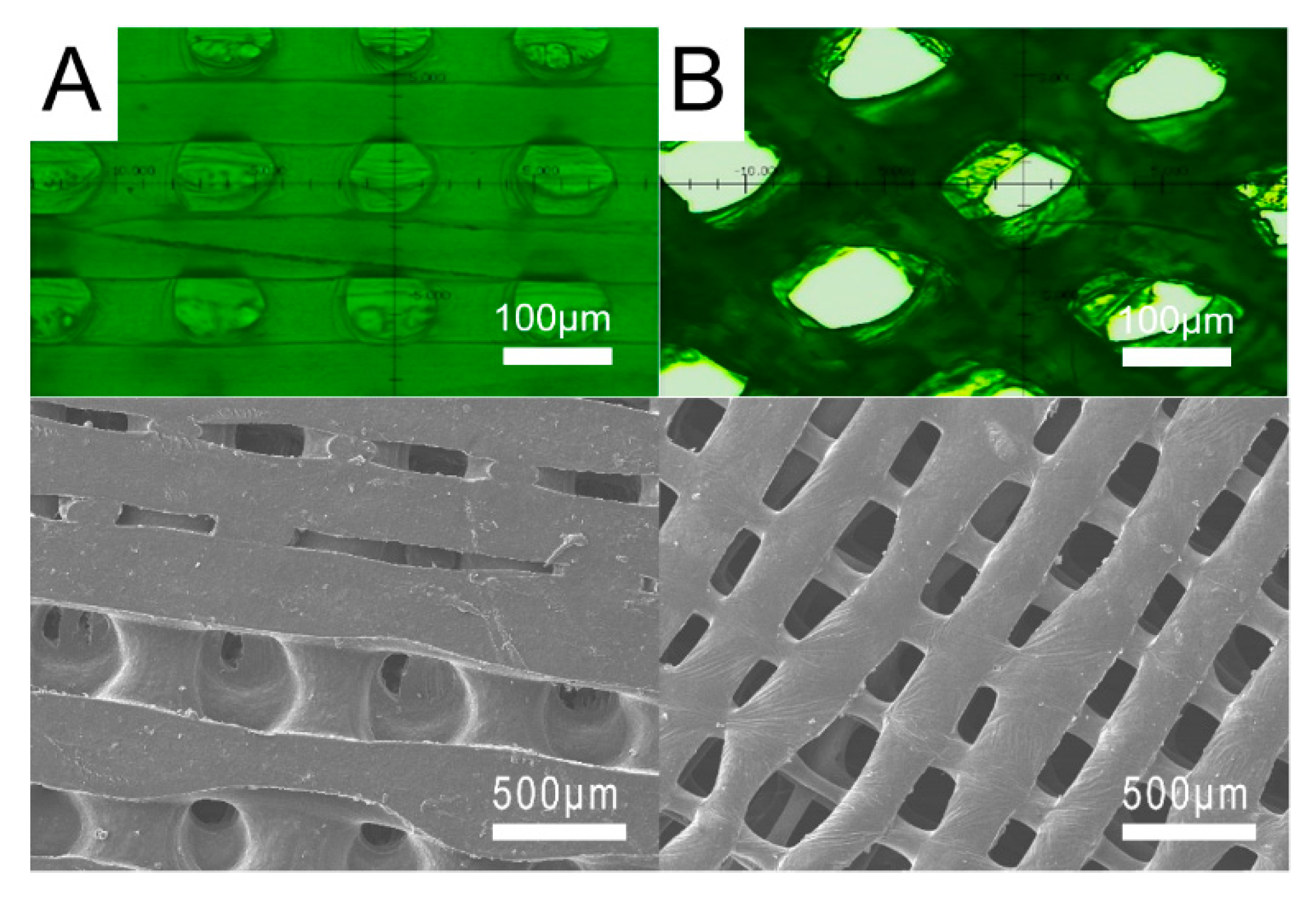
Figure 12 shows the surface images of the parts manufactured with orientations of 90° and 45°. Obviously, 45° resulted in more large pores on the surface. Furthermore, compared to 90°, 45° resulted in sharp rectangular pores. Meanwhile, due to the different print orientation of infill, the interlayer fusion of PCL strips might be different, which in turn leads to various bonding intensities and relevant mechanical strengths. This might explain why the strength of the 30° manufactured part is higher than that of the 45°.
When these pores are subjected to external forces, stress concentrations may occur and lead to fractures. The strength decreased accordingly. We were able to successfully manufacture 2D and 3D products of various geometries by using the optimum processing conditions of a PCL/DCM ratio of 5 g/7.2 mL, a fill density of 80%, a tip moving speed of 40 mm/s, and a print orientation of 90°, as shown in
Figure 13.
3.2. Influence of Solvent
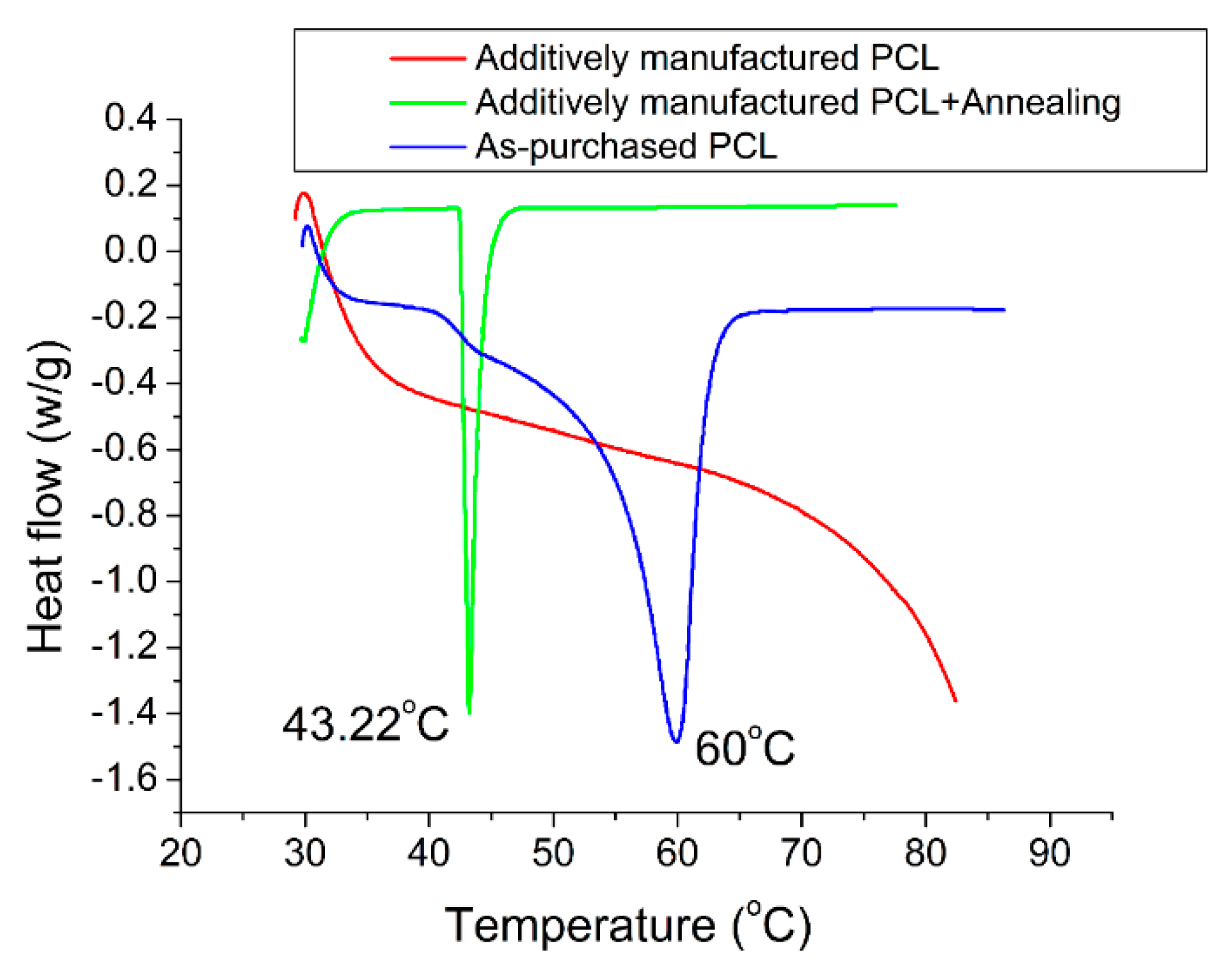
Figure 14 shows the DSC curves of the virgin PCL materials, the solution extrusion manufactured PCL, and the manufactured PCL parts after being annealed in an oven at 50 °C for 1 h. The virgin PCL exhibited a crystallization exotherm near 60 °C. After the addition of solvent, the solution fabricated PCL became an amorphous state and showed no obvious crystallization exotherm or melting temperature on the DSC curve. After the annealing process, the annealed parts regained the crystallization exotherm, and the melting temperature decreased to around 42 °C.
4. Discussion
Two factors might affect the mechanical properties of an additively manufactured product and determine the success of the product in a given application. The first factor is the healing or fusion of layer interfaces, and the second is the size of the pores. To produce parts of greater strength in solution extrusion additive manufacturing, the enhancement of chain entanglements [
15] at the strip interface is essential and is responsible for the final mechanical properties of additively manufactured products [
16].
In solution extrusion, solvent exhalation and diffusion of molecular chains occur at the solidification stage of polymeric materials. It has been reported that in the solution processing of polymers, the optimum solution is a semi-dilute, mildly entangled pattern, which occurs at the critical entanglement concentration Ce [
17] (10–12 w/v% for PCL when DCM is used as the solvent [
18]). This period is a critical point between a semi-dilute unentangled pattern and a semi-dilute mildly entangled pattern. In this range, enhanced healing at the strip interfaces can be anticipated. Despite the PCL concentration used (approximately 7%) in this work being less than optimal, fusion and healing at the interface was still expected. As for the second factor, a solution extrusion additively manufactured part may have tiny incompletely fused pores and cracks, which may lead to stress concentrations when subjected to external forces. The strength of fabricated parts is thus decreased.
The experimental results in
Figure 5 suggest that the strength of the manufactured parts increased with the volume of DCM. The parts made with PCL/DCM = 5 g/7.2 mL had the highest mechanical strength. When less solvent was used, the solvent can volatilize too rapidly, leading to insufficient time for the polymeric solution to go through molecular entanglement at the strip interfaces. A higher concentration of DCM maintains the polymeric materials in a semi-dilute state for a sustained period of time and helps the polymeric strips to fuse and close up at the interfaces. This occurs not only in the same layer but also across various layers, as shown in
Figure 9. Thus, the parts exhibited higher strength.
The data in
Figure 6 suggest that the mechanical properties of the parts increased with the fill density. The fill density is defined as the amount of polymer used in fabricating a specimen. A higher fill density implies more plastic material within the manufactured samples, thus resulting in a stronger product. Furthermore, filling the parts with more material also leads to smaller pore sizes (
Figure 10), which increases the manufactured part’s quality. Meanwhile, as pointed out earlier, the strength of the manufactured parts also increased with the volume of DCM. Therefore, there exists a balance between volume of DCM and amount of polymer that leads to the maximum strength.
The empirical data in
Figure 7 suggest that the strength decreases with the print speed. Once the solution is expelled from the dispensing tip, the solvent starts to volatilize. When the tip is too fast, not as much time is allowed for the solution to go through molecular entanglement at the strip’s interface (
Figure 11). In addition, the solvent may not have enough time to evaporate. The excessive solvent may spread and dissolve the neighboring strips and decrease the chain entanglement. The strength decreased accordingly.
The parts fabricated with a 45° print orientation of infill exhibited the lowest strength, while 90° resulted in the greatest part strength. One possible explanation is that the 90° orientation of extruded strips limits the amount of solvent that quickly evaporates. There is sufficient time for the polymeric liquid to experience molecular entanglement at the interfaces (
Figure 12A). The mechanical strength of specimens increased accordingly. An orientation of 45° resulted in diamond-shape pores (
Figure 12B). When subjected to external tensile forces, these diamond-shaped pores may experience stress concentrations at the corners. The fabricated products thus exhibited the worst tensile properties.
Finally, the polymer crystallization may be changed by placing the material in an environment with organic solvents [
19,
20]. In the presence of DCM, PCL materials turned into an amorphous state [
21]. Despite their lowest crystallinity, the experimental data demonstrated that the solution manufactured PCL parts exhibited excellent ductility (
Figure 4B). Furthermore, the annealing helps to regain the crystallinity of the polymeric materials [
22]. All these results demonstrated the feasibility of the solution extrusion additive manufacturing technique for PCL materials.

 ,
, 


