Article

Pressure Control Algorithm Based on Adaptive Fuzzy PID with Compensation Correction for the Tractor Electronic Hydraulic Hitch

1
College of Engineering, China Agricultural University, Beijing 100083, China
2
Beijing Key Laboratory of Optimized Design for Modern Agricultural Equipment, Beijing 100083, China
3
Sinopec Research Institute of Petroleum Engineering, Beijing 100101, China
*
Author to whom correspondence should be addressed.
Appl. Sci. 2020, 10(9), 3179; https://doi.org/10.3390/app10093179
Submission received: 4 April 2020 / Revised: 30 April 2020 / Accepted: 30 April 2020 / Published: 2 May 2020

Abstract

:
In order to realize the pressure control of the tractor electronic hydraulic hitch in the fields, the pressure control algorithm is essential. In this study, combining the kinematics model with the dynamic model of ploughing and the hydraulic system model, an adaptive fuzzy PID controller is proposed to adjust the real-time data of the PID parameters for the pressure control of the tractor electronic hydraulic hitch. The feasibility of the proposed controller was verified by simulation. Next, a pressure control experimental with the real vehicle experiment platform was carried out under three control algorithms of the traditional PID, the traditional PID with compensation correction and the adaptive fuzzy PID with compensation correction in verifying the pressure control effect of the tractor in different controllers. When the system was stable, the experimental results showed that the input was 1.5 MPa step signal with response time in the traditional PID controller of 2.5 s, fluctuation range of 0.5 MPa. However, the response time in the adaptive fuzzy PID with compensation correction was 1.5 s, fluctuation range of 0.3 MPa. The responding time was 40% lower, and the pressure fluctuation range was reduced by 40%. In conclusion, the proposed algorithm successfully realized the pressure control of the tractor. The proposed adaptive fuzzy PID with compensation correction in this paper has a better dynamic performance.

1. Introduction

The hitch is a particular part used with a tractor for the lifting of agricultural tools and control of plough depth. The operation quality and efficiency of the tractor unit could be affected directly by control performance [1]. Since the requirements of elaborate operation were continuously improved upon [2,3], the accuracy and the control stability, as well as the response speed of the tractor hitch, were expected to be better. With the development of hydraulics, electro-hydraulic control has received increased attention in the field of an intelligent agricultural tractor [4,5,6]. Many different control methods have been developed for the tractor electronic hydraulic hitch control system, including the position control, draft control [7,8,9], draft-position control [10] and slip rate control [11,12,13]. The efficiency of tractor ploughing can be greatly improved by adopting corresponding control methods under different working conditions [14]. When the tractor ploughs the ripe farmland, the resistance of ploughing is small, and the floating control is widely used. The profiling function of floating control is more accurate than the traditional position control and draft control. Moreover, by using pressure control, the effect of floating control can be improved, and the weight of the farm tools which borne by the land wheel could be moved to the driving wheel of the tractor. Accordingly, the adhesion of the driving wheels and the efficiency could be improved [15,16,17]. At present, the research on the pressure control algorithm of the tractor electro-hydraulic hitch was lacking, so it is of great significance to analyze the pressure control process and control algorithm of the tractor.
In the actual field operation, there are inevitable fluctuations in the ground, and the soil environment constantly changes [18,19], which makes the hydraulic cylinder produce forced displacement and causes the fluctuation of the system pressure. Accordingly, the system becomes unstable. There are also various studies on control algorithms for the fluctuation of the system pressure. Yuan et al. [20] proposed an adaptive optimal decoupling control strategy, which can effectively eliminate the coupling between the force control system and improve the tracking accuracy of the system. Based on the quantitative feedback technology of online adjustment, Dinh et al. [21] designed the robust controllers of the loading system. In reference [22,23], a nonlinear adaptive method of adjusting parameters by backstepping control algorithm was adopted. Compared with the above control algorithms, adding compensation and correction link in the system has the advantages of simple structure and easy implementation process, which can overcome the pressure fluctuation. Accordingly, it is widely used in engineering [24,25].
However, there are always uncertain factors in the real working process, such as the non-linearity of mechanical structure and the change of valve parameters, which make the compensation link not robust [26]. The accurate mathematical model was not required in the fuzzy controller. Accordingly, the control mechanism and control strategy are easy to accept and understand and have strong robustness and self-adjusting ability. The adaptive fuzzy PID controller has the advantages of a simple principle, a convenient operation, and strong adaptability, and its control quality is insensitive to changes in the nonlinear controlled object [27,28]. Accordingly, the adaptive fuzzy PID controller is very suitable for agricultural machine operating in a complex environment [29,30,31]. Therefore, a pressure control algorithm was proposed by taking full advantage of the adaptive fuzzy PID control and compensation correction.

2. Mathematical Model of the Pressure Control System for the Tractor Electronic Hydraulic Hitch

Pressure Control for the tractor electronic hydraulic hitch is a kind of hydraulic weight increasing mechanism. The basic principle is to maintain a certain pressure in the hydraulic cylinder, which has a certain lifting effect on the plough, but it is not enough to lift the plough. As a result, the vertical load of the land wheel was reduced. Thus, the profiling function can be ensured, the vertical load of the driving wheel is increased, and the efficiency could be improved.
The system of pressure control for the tractor electronic hydraulic hitch mainly includes linkage, hydraulic system, and electrical system, etc. In the study, the mathematical model of the system of pressure control for the tractor electronic hydraulic hitch was established by analyzing the motion of the tractor electronic hydraulic hitch and the dynamic modelling of ploughing operation, which provided the foundation for the design and analysis of the pressure controller.

2.1. Analysis of Kinematics of the Tractor Electronic Hydraulic Hitch

The structure of the tractor electronic hydraulic hitch is shown in Figure 1. The triangle ANC structure is composed of hydraulic cylinder AC and lifting arm ND. The angle of lifting arm ND is changed by the telescoping hydraulic cylinder. The quadrilateral structure NDEB is composed of lower pull rod BV, lifting rod de and lifting arm ND. The angle of lifting arm ND is transmitted to the pull-down rod BV to drive the lower pull rod BV to rotate. Another quadrilateral mechanism ABCD is composed of the upper pull rod mg, pull-down rod BV and implemented so as to lift and lower the plough.
The vertical line passing through point B as the horizon is recorded as the y-axis, positive upward; the horizon is recorded as the x-axis, positive left; the intersection point O is recorded as the coordinate origin.
In the triangular ANC, l represents the length of two points, and the coordinates of each point are as follows:
{ x N l NC cos ( α C ) = x A l AC cos ( α AC ) y N + l NC sin ( α C ) = y A + l AC sin ( α AC )
In the quadrilateral NDEB, the coordinates of each point are as follows:
{ x D l DE cos ( β E ) = x B l BE cos ( α V ) y D + l DE sin ( β E ) = y B + l BE sin ( α V )
Similarly, in the quadrilateral MGVB, the coordinates of each point are as follows:
{ x M l MG cos ( α G ) l GV cos ( β V ) = x B l BV cos ( α V ) y M l MG sin ( α G ) l GV sin ( β V ) = y B + l BV sin ( α V )
The coordinates (xW, yW) of the plough center of mass point W, the coordinates (xU, yU) of the axle center of land wheel point U, and the coordinates (xP, yP) of the tip of the plough in the middle point P in the x-o-y coordinate system were defined as follows, respectively:
{ x W = x G l GW cos ( β V β W ) y W = y G l GW sin ( β V β W ) x U = x G l GU cos ( β V β U ) y U = y G l GU sin ( β V β U ) x P = x G l GP cos ( β V β P ) y P = y G l GP sin ( β V β P )
In accordance with the geometric relationship shown in Figure 1, the coordinates (xQ, yQ) of the velocity instantaneous center point Q in the x-o-y coordinate system were defined as follows:
{ x Q = y V y G + k 1 x G k 2 x V k 1 k 2 y Q = y V + k 2 ( x Q x V )
where k 1 = y M y G x M x G , k 2 = y B y V x B x V .
The turning speed of the plough’s center of mass could be calculated as follows:
α ˙ W = l MG α ˙ G l GQ
where αw is the turning angle of the plough’s center of mass.
When tractor ploughing operation is approximately stable, the road roughness can be recorded as Zg (t) [32], and it can be obtained from Figure 1 that the land wheel settlement ZR is as follows:
{ Z ˙ g ( t ) + 2 π n 0 v Z g ( t ) = n 0 2 π G q ( n 0 ) v W ( t ) Z R = Z g ( y U r R )
where q(t) is the road roughness function; W(t) is the Gaussian white noise with the mean value of zero; n0 is the road space cutoff frequency.

2.2. The Dynamic Model of the Tractor Electronic Hydraulic Hitch

To simplify the analysis, the soil resistance of plough is equivalent to that of the middle plough. As shown in Figure 2, the force on the plough body could be divided into horizontal resistance and vertical resistance. The vertical resistance included the steady part of the plough body in the vertical direction and the damping force in the process of the plough body movement [33].
The total steady resistance of the plough could be calculated as follows:
R = n p b p k p h p
where np is the number of ploughs, kp is the resistance coefficient; bp is the width of the single plough; hp is the depth of plough.
The horizontal resistance was calculated as follows:
R H = R cos ( φ )
where φ is the angle between the total steady resistance of the plough body and the horizontal line.
It was assumed that the acting line of the vertical transient force of the plough body is approximately coincident with the acting line of the vertical component of the steady working resistance of the plough body. The vertical resistance of the plough body is as follows:
R V = R sin ( φ ) + R H y ˙ RV v
The location of the force bearing point of the plough body is as follows:
{ S RH 0.36 h p S RV 0.54 h p
As shown in Figure 3, before establishing the dynamic model of the tractor electronic hydraulic hitch, the following assumptions were made:
(1) Ignore the shock of the wheel on the uneven soil, due to the low speed of ploughing.
(2) Ignore the mass of each member bar.
(3) The deformation stiffness of soil is far less than that of the implement members. Accordingly, the deformation of the plough and members is ignored.
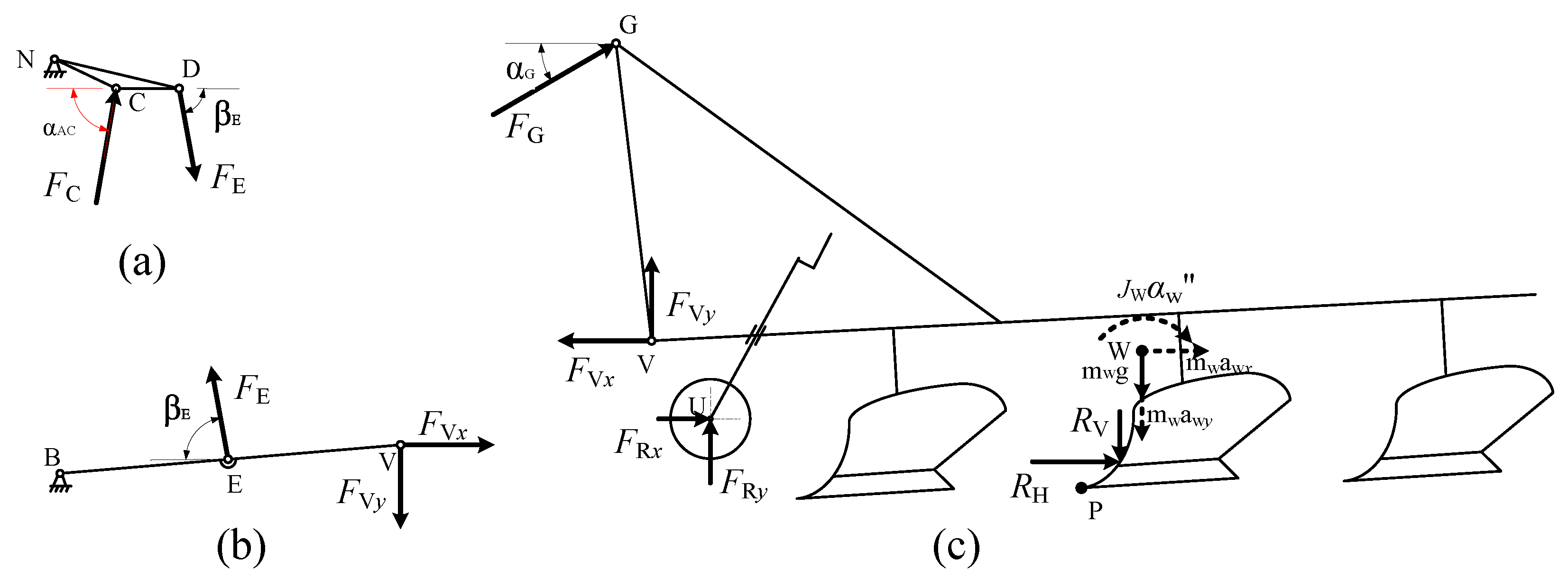
As shown in Figure 3c, the forces applied to the plough include the soil resistance of the plough body, the vertical reaction force FRy and the horizontal rolling resistance FRx of the soil-applied to the wheel, the plough gravity mWg, the force FG at the upper pull rod, and the horizontal FVx and vertical force FVy at the pull rod.
We are taking plough as the research object. The equation of longitudinal and lateral dynamics of the plough and the equation of using D’Alembert’s principle for the sum of torques around V can be written as follows:
{ R H + F G cos α G F V x + F R x + m W a W x = 0 F G sin α G + F V y R V + F R y m W ( g + a W y ) = 0 R H ( y V y P s R H ) R V ( x V x P + s R V ) + F R y ( x V x U ) + F Rx ( y V y U ) m W ( g + a W y ) ( x V x W ) + m W a W x ( y V y W ) F G cos ( α G ) ( y G y V ) F G sin ( α G ) ( y G y V ) ( J W + m W ( ( x V x W ) 2 + ( y V y W ) 2 ) ) α ¨ W = 0
The vertical force of the land wheel could be calculated by the following formula [34,35]:
F R y = { 1 3 ( 3 n ) ( k c + b k φ ) 2 r R z R 2 n + 1 2 z R > 0 0 z R 0
The rolling resistance of the land wheel is approximately taken as follows:
F R x F R y f
where f is rolling resistance coefficient.
As shown in Figure 3b, the pull-down rod BV is taken as the research object. The force FE at the hinge point E could be calculated as follows:
F E l EB sin ( β E + α V ) F V x ( y V y B ) F V y ( x B x V ) = 0
F E = F V x ( y V y B ) + F V y ( x B x V ) l EB sin ( β E + α V )
Similarly, as shown in Figure 3a, the load force FC of the hydraulic cylinder can be obtained as follows:
F C = F E l ND sin ( α D + β E ) l NC sin ( α AC α C )

2.3. Mathematical Model of the Hydraulic System for the Tractor Electronic Hydraulic Hitch

When establishing the dynamic model of the hydraulic system, the following assumptions are made first: neglects the influence of oil density and compressibility, the viscous damping coefficient of the system is ignored, system oil supply pressure is constant and returns oil pressure is zero.
The flow equation of the proportional valve is:
q L = K q x F K c p L
where xF is spool displacement of the proportional valve, Kq is proportional valve flow gain, Kc is flow pressure coefficient, and pL is load pressure.
Then the flow continuity equation of the hydraulic cylinder can be expressed as:
q L = A L d x L d t + C t p L + V L β e d p L d t
where AL is the effective area of the hydraulic cylinder, xL is the motion displacement of hydraulic cylinder, Ct is the total leakage coefficient of hydraulic cylinder, VL is the total volume of two cavities of hydraulic cylinder, and βe is the effective volume elastic modulus of hydraulic oil.
Without considering the elastic load of the hydraulic system, the system force balance equation is:
A L p L = m L x ¨ L + F C
where mL is the equivalent mass of hydraulic cylinder piston, and FC is the load force of hydraulic cylinder.
The incremental Laplace transformation of equation 18–20 is as follows:
{ Q L = K q X F K C P L Q L = A L X L + C t P L + V L β e P L s A L P L = m L X L s 2 + F C
The transfer function of the pressure sensor is:
U f = K f P L
where Kf is the conversion factor of the pressure sensor.
The transfer function of the proportional amplifier is:
I = K a ( U r U f )
where Ka is the gain of the proportional amplifier, Ur is the analogue reference voltage signal of system input.
The transfer function of the proportional electromagnet is assumed to be:
G sv = X F I = K sv T s v s + 1
where KSV is the current gain and TSV is the time constant.

3. Design of the Pressure Control Algorithm

3.1. The Compensation Correction Link

In the pressure control system, the transfer function Gc(s) of the compensation correction link selected in this paper is as follows:
G c ( s ) = A L K q G sv ( s )
According to Equations (21)–(25), the block diagram of the pressure control system with compensation correction is as follows:
It can be seen from Figure 4 that when the parameters of the valve are constant, the pressure control system with compensation correction can completely compensate the impact of the forced flow of the hydraulic cylinder caused by the ground fluctuation in theory.
However, in the actual operation process, there are nonlinear factors in the mechanical and hydraulic parts of the tractor electronic hydraulic hitch, and there are uncertain factors such as soil environment changes in the process of pressure control. According to the factors, in this paper pressure control algorithm based on adaptive fuzzy PID with compensation correction was proposed for the tractor electronic hydraulic hitch.

3.2. Design of the Adaptive Fuzzy PID Algorithm

3.2.1. The Adaptive Fuzzy PID Control Algorithm

The principle of the adaptive fuzzy PID controller for the pressure control system is shown in Figure 5. The system pressure deviation e and the deviation change rate ec are used as the input of the adaptive fuzzy PID controller. The PID parameters ∆Kp, ∆Ki, and ∆Kd are outputs of the controller. The PID parameters were adaptively adjusted online by the fuzzy inference method, which can meet different requirements of the different deviation e and the deviation change rate ec so that the controlled object achieves the quantitative dynamic and static performance.
According to the adaptive fuzzy PID control principle, the adaptive fuzzy PID controller with compensation correction could be defined as follows:
u ( t ) = ( K p 0 + Δ K p ) e ( t ) + ( K i 0 + Δ K i ) 0 t e ( x ) d ( t ) + ( K d 0 + Δ K d ) d e ( t ) d t + d x L d t G c ( s )
where Kp0, Ki0, and Kd0 are the initial set values of PID parameters.

3.2.2. Control Variable Fuzzification and Membership Function

As mentioned above, the parameters ∆Kp, ∆Ki, and ∆Kd are outputs. First of all, through closed-loop operation or simulation, the dynamic characteristics of the system were observed, and the parameters were repeatedly debugged, according to the influence of every parameter on the system. The PID control parameters were determined until a satisfactory response occurred, which were set as the initial parameters, Kp0, Ki0, and Kd0, of the adaptive fuzzy PID controller. For the PID controller, the control parameters are Kp0 = 0.5, Ki0 = 0.6, and Kd0 = 0.02. The appropriate fuzzy domain was then selected, based on the parameters, and the parameters ∆Kp, ∆Ki, and ∆Kd of the adaptive fuzzy PID control were determined by the fuzzy controller in real-time.
Based on the fuzzy control theory, the input and output variables were fuzzified as follows:
Pressure deviation e. The basic domain is: [−1.5 MPa,1.5 Mpa], the quantization domain is: {−3, −2, −1,0,1,2,3} = {NB, NM, NS, ZO, PS, PM, PB}, and the quantization factor is: 3/1.5 = 2;
Pressure deviation change rate ec. The basic domain is: [−15,15], the quantization domain is: {−3, −2, −1,0,1,2,3} = {NB, NM, NS, ZO, PS, PM, PB}, and the quantization factor is: 3/15 = 0.2;
Proportional parameter ∆Kp. The basic domain is: [−0.5,0.5], the quantization domain is: {−1,2/3,1/3, 0,1/3, 2/3, 1} = {NB, NM, NS, ZO, PS, PM, PB}, and the quantization factor is: 1/0.5 = 2;
Integration parameter ∆Ki. The basic domain is: [−1,1], the quantization domain is: {−1,2/3,1/3, 0,1/3, 2/3,1} = {NB, NM, NS, ZO, PS, PM, PB}, and the quantization factor is: 1/1 = 1;
Differential parameter ∆Kd. The basic domain is: [−0.02,0.02], the quantization domain is: {−1,2/3,1/3, 0,1/3, 2/3,1} = {NB, NM, NS, ZO, PS, PM, PB}, and the quantization factor is: 1/0.02 = 50.
The input and output variables are summarized in Table 1.
With the simple operation and small memory consumption of triangular membership function, they were selected as the membership function of the input and output variables. Seven fuzzy subsets are selected as triangular membership functions, which are NB, NM, NS, ZO, PS, PM and PB. The degree of membership functions corresponding to the input and output variables are shown in Figure 6.

3.2.3. Adaptive Fuzzy PID Control Rules

In the adaptive fuzzy PID controller, the three parameters work together to affect the system, which must be considered. The tuning requirements of ΔKp, ΔKi, and ΔKd under different deviations |e| and deviation change rate |ec| are as follows:
(a)
When |e| is a large value, to speed up the response of the system, the ∆Kp value should be larger; ∆Ki is often set to 0 to avoid the differential oversaturation caused by the instantaneous increase of the |e| value
(b)
When |e| is a medium value, to reduce the overshoot of the system, the values of ∆Kp, and ∆Ki should be smaller and the value of ∆Kd should be appropriate to speed up the response of the system.
(c)
When |e| is a small value, to keep the good steady-state performance of the system, ∆Kp and ∆Ki should be set as larger values, and the value of ∆Kd is up to |ec|. When |ec| is small, ∆Kd takes a larger value. When |ec| is large, ∆Kd should take a smaller value to avoid oscillation of the system.
According to the tuning requirements above, the fuzzy control rules for PID control parameters were designed as follows:
According to the adaptive fuzzy PID control rule established below in Table 2, the dynamic tunings of ∆Kp, ∆Ki, and ∆Kd were obtained. According to the membership degree of each fuzzy subset and the fuzzy control model of each parameter, the fuzzy matrix table of PID parameters is designed by using fuzzy synthesis reasoning and the corrected parameters ∆Kp, ∆Ki, and ∆Kd are found out. The proportional, integral, and differential parameters Kp, Ki and Kd of PID controller are as follows:
{ K p = K p 0 + Δ K p K i = K i 0 + Δ K i K d = K d 0 + Δ K d
In conclusion, the adaptive fuzzy PID controller model established in this paper is shown in Figure 7.

4. Simulation Analysis

To verify the effectiveness of the feasibility of the adaptive fuzzy PID with compensation correction pressure control algorithm, the simulation model of pressure control for the electronic hydraulic hitch was established in MATLAB.
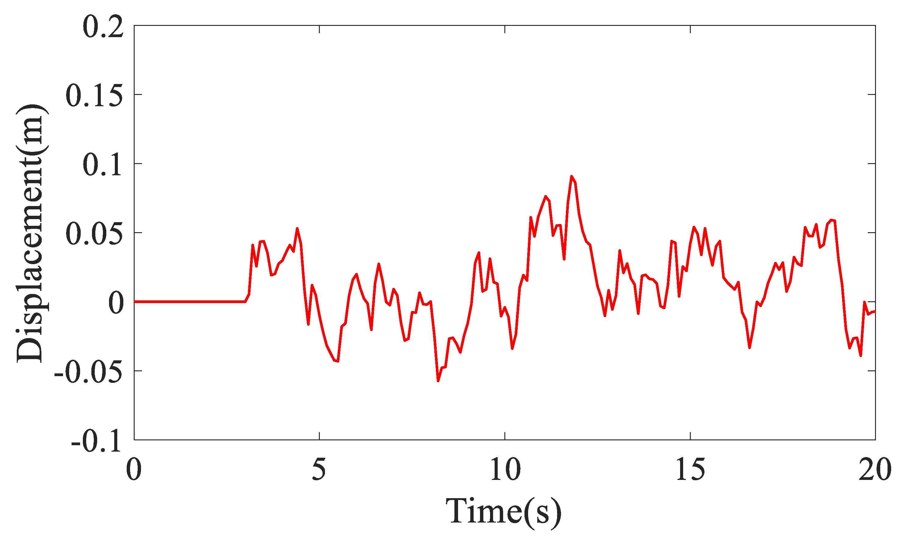
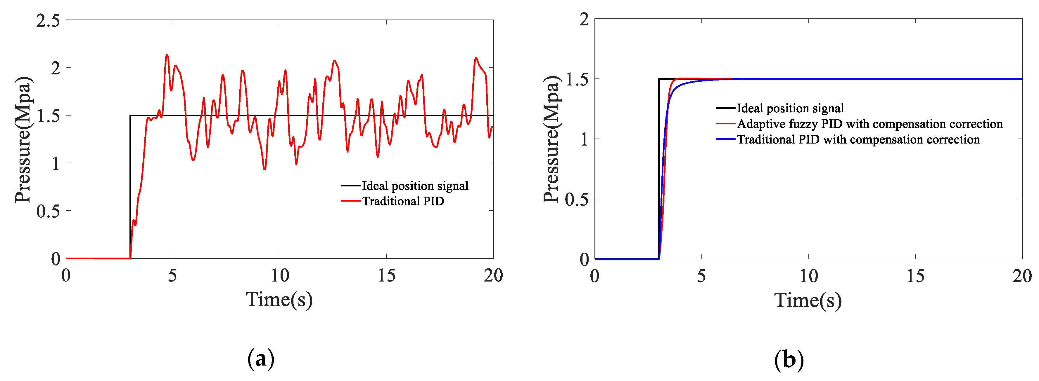
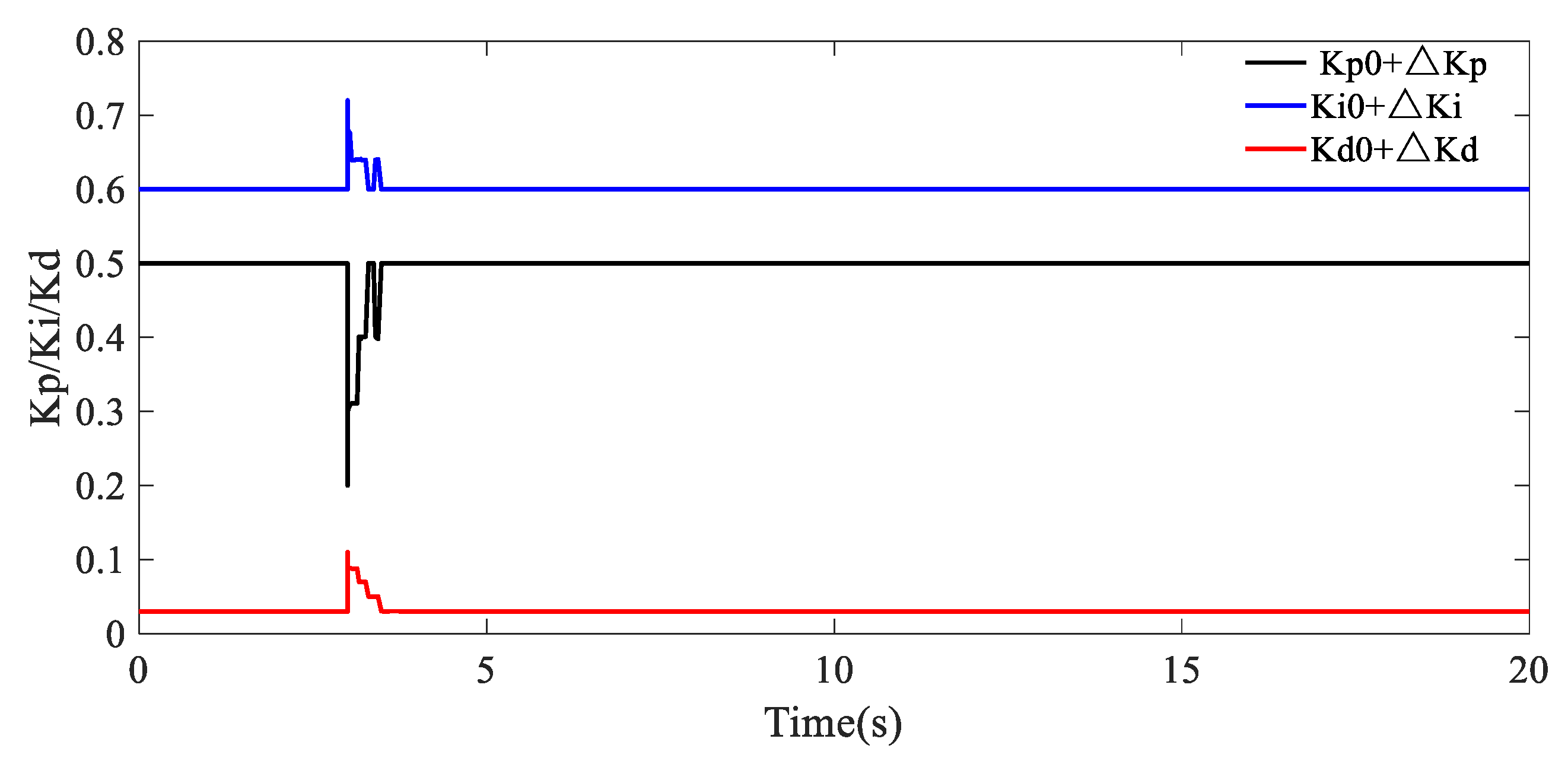
In the simulation process, the pressure control for the electronic hydraulic hitch is in constant value control with interference during tractor operation, so that the step signal of 1.5 MPa is selected as the system input signal. Class D road spectrum is selected as the excitation signal of the land wheel, and road irregularity is shown in Figure 8. The step signal response curves of the pressure control for the electronic hydraulic hitch of the traditional PID, the traditional PID with compensation correction and adaptive fuzzy PID with compensation correction are as shown in Figure 9, respectively. Fuzzy adaptive adjustment of Kp, Ki and Kd are as shown in Figure 10, respectively.
The simulation analysis when different control algorithms are adopted is shown in Table 3. When the traditional PID is used to control the pressure, the response time is the only 1 s, but the pressure fluctuates greatly, and the stability and robustness of the system are poor. When the traditional PID is added with compensation correction, the system has no overshoot, and the response time is about 3.5 s. When the adaptive fuzzy PID control algorithm with compensation correction is adopted, the system has no overshoot, but the response time is only 1 s. The dynamic performance of the system is better than others.
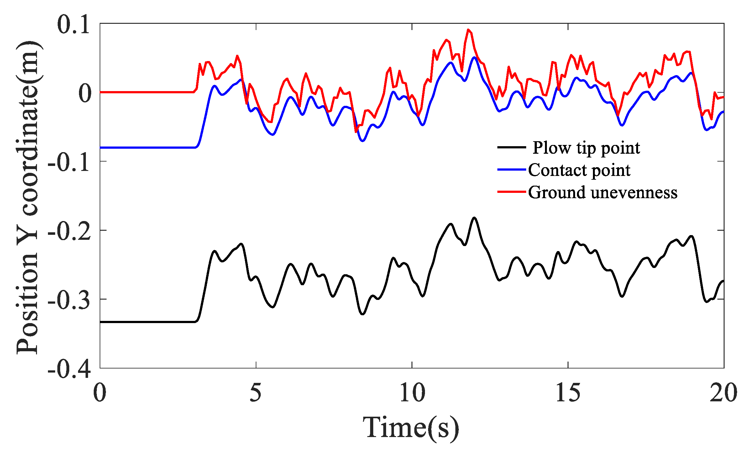
To verify the effect of the profiling function of the pressure control system for the tractor electronic hydraulic hitch, the position Y coordinate curves of the point of the plough tip and the contact point between the ground wheel and the ground, and the ground unevenness are as shown in Figure 11. The simulation results show that when the tractor adopts the pressure control, the soil subsidence of the land wheel is reduced, the tractor ploughing can keep the profiling function and the ploughing depth is uniform, and the better agronomic requirements can be obtained compared with the traditional position control.

5. Field Experimental Results and Discussion

5.1. Field Experimental Scheme

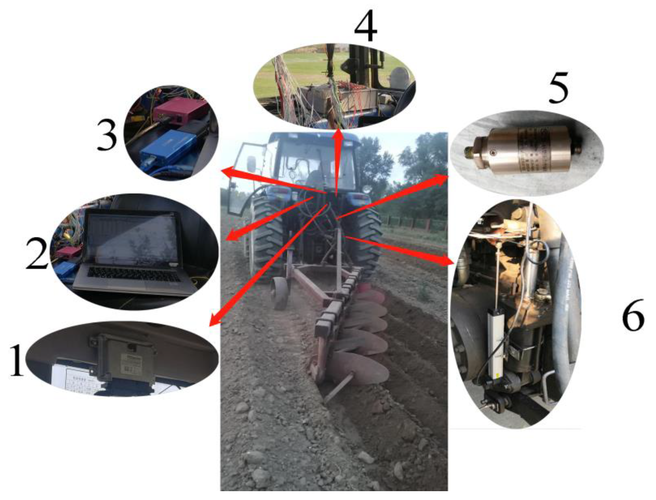
The field experiment was conducted at the Shangzhuang Experimental Base of China Agricultural University. As shown in Figure 12, it mainly includes tractor, pressure control system and communication module. The original tractor electro-hydraulic hitch was changed into pressure control experimental platform. The pressure sensor is ak-4, the range of pressure sensor is 0~10 MPa; the output voltage is 0~5 V, the relative error is ± 0.5%. The displacement sensor is Miran, the range of displacement sensor is 0~250 mm, the output voltage is 0~5 V, the relative error is ± 0.1%.
The effectiveness of the pressure control algorithm is verified by simulation. The control program is written in codesys and downloaded to TTC60 through CAN0. The parameters of the controller were adjusted on the field tractor until a satisfactory result occurred. CAN0 and CAN1 were connected to the computer, respectively. When CAN0 is connected to PC, the parameters of the controller can be observed in codesys in real-time. During the experiment, and according to the requirement of ploughing depth, the land wheel was adjusted to a reasonable position; the upper pull rod was adjusted to maintain a certain angle of penetration; the left and right pull rods were adjusted to make the plough in a horizontal position; then the lowering valve was opened to make the plough in a floating state. The tractor is adjusted to B1 gear, and the speed is stable at 6 km / h. When the plough is completely in the soil, the control signal is sent to the controller through CAN0. The experimental data, such as the hydraulic cylinder pressure and control input signal, were saved in real-time through CAN1.

5.2. Analysis of Experimental Results

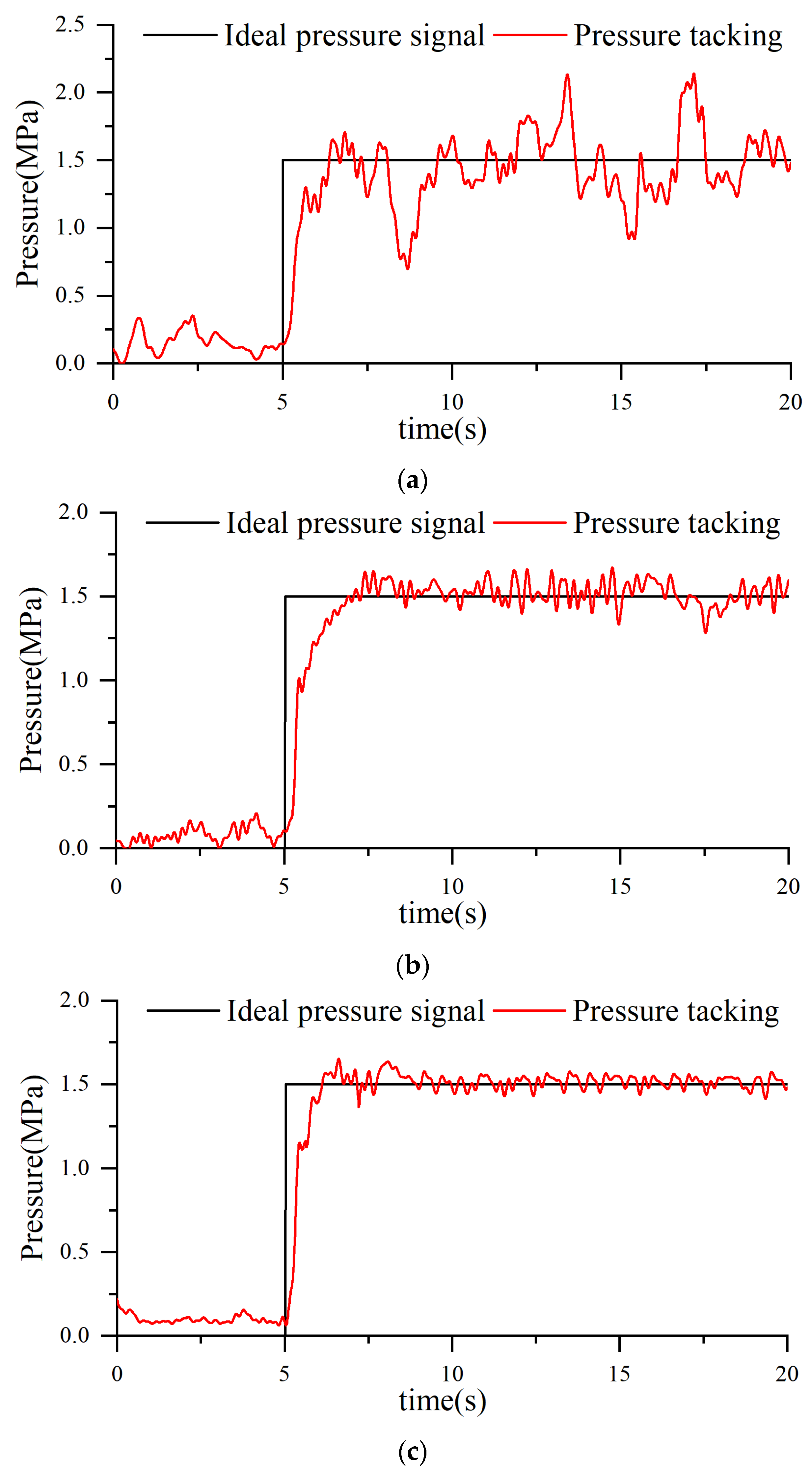
Figure 13 shows experimental results, where the red line is the actual pressure. The pressure tracking curves of traditional PID, traditional PID with compensation correction and adaptive fuzzy PID with compensation correction control algorithm are shown in Figure 13a,b,c, respectively.
From Figure 13a, it can be seen that the system response is fast, reaching 1.5 MPa in about 2 s, but the pressure tracking curve fluctuates greatly, which fluctuates between the minimum 0.7 MPa and the maximum 2.1 MPa, and the system robustness is poor when the traditional PID algorithm without compensation correction is adopted.
From Figure 13b, it can be seen that the system pressure reaches 1.5 MPa in 2.5 s, and when the system is stable, the pressure tracking curve fluctuates between the minimum 1.2 MPa and the maximum 1.7 MPa under the control of traditional PID algorithm with compensation correction.
From Figure 13c, it can be seen that the system pressure only reaches 1.5 MPa in 1.5 s, and when the system is stable, the pressure tracking curve fluctuates between the minimum 1.3 MPa and the maximum 1.6 MPa under the control of adaptive fuzzy PID algorithm with compensation correction. The fluctuation is caused by the forced flow caused by the uncertain parameters of the valve and other factors, which cannot be fully compensated. The dynamic performance of the system is better than others.
The system response performance under the control of various algorithms is calculated and summarized in Table 4. From that table, we find that the adaptive fuzzy PID control algorithm with compensation correction proposed in this article has a good effect for the system response. From 2.5 s when only traditional PID with compensation correction control to 1.5 s, which achieves the experimental effect of pressure tracking control using the adaptive fuzzy PID control algorithm with compensation correction. The responding time was 40% lower, and the pressure fluctuation range is reduced by 40% from 0.5 MPa to 0.3 MPa. According to the field experimental results, the pressure control system with the proposed algorithm has a favourable dynamic response character, high tracking accuracy, and sufficient robustness to meet the field performance requirements of the tractor.

6. Conclusions

In the manuscript, the adaptive fuzzy PID with compensation correction pressure control algorithm for the electronic hydraulic hitch is proposed. This controller can adjust the PID control parameters in real-time in the fuzzy domain, which can make the adaptive fuzzy PID controller with compensation correction output the best control variables. The pressure control experimental platform is modified. Simulations and field experiments are performed to verify the effectiveness of the pressure control system. When the system is stable, the experimental results are shown that the input is 1.5 MPa step signal with response time in the traditional PID controller of 2.5 s, fluctuation range of 0.5 MPa. But the response time in the adaptive fuzzy PID with compensation correction is 1.5 s, fluctuation range of 0.3 MPa. The responding time is 40% lower, and the pressure fluctuation range is reduced by 40%. In conclusion, the adaptive fuzzy PID with compensation correction pressure control algorithm proposed in this study can realize the pressure control of the electronic hydraulic hitch, which is beneficial to improve system dynamic performance and can satisfy the agronomic requirements of the field operation of the tractor.
This article mainly completes the pressure control work. It should be pointed out that there is no consideration on the coupling effect between the pitching motion of the tractor and the ploughing operation, and the slip rate of the tractor is not reflected in the mathematical model. In the field experiment, we did not add controlled disturbances to investigate the behaviour of the adaptive controller works. In subsequent research, we will consider applying these results to the energy conservation background of the tractor slip rate, as well as to do further theoretical and experimental research, adding some controlled disturbances in the experiments to investigate how the adaptive controller behaves.

Author Contributions

Writing, original draft preparation, C.L. and E.M.; Methodology, E.M.; Data Curation C.L., J.G. and J.Z.; Validation, C.L., Z.L. and Y.D.; Resources, Z.Z. and E.M.; Funding Acquisition, E.M. All authors have read and agreed to the published version of the manuscript.

Funding

This research was funded by the National Key Research and Development Program, Grant Number 2017YFD0700101.

Acknowledgments

This work was financially supported by the National Key Research and Development Program (Project No. 2017YFD0700101).

Conflicts of Interest

The authors declare no conflict of interest.

References

  1. Kovačev, I.G.; Košutić, S.; Jejčič, V.; Čopec, K.; Gospodarić, Z.; Pliestić, S. Impact of Electronic-Hydraulic Hitch Control on Rational Exploitation of Tractor in Ploughing. Hrvatski Strojarski i Brodograđevni Inženjerski Savez 2008, 50, 287–294. [Google Scholar]
  2. Bin, X.; Zhongbin, W.U.; Enrong, M. Development and Prospect of Key Technologies on Agricultural Tractor. Trans. Chin. Soc. Agric Mach. 2018. [Google Scholar] [CrossRef]
  3. Moreda, G.P.; Muñoz-García, M.A.; Barreiro, P. High voltage electrification of tractor and agricultural machinery—A review. Energ Convers. Manag. 2016, 115, 117–131. [Google Scholar] [CrossRef]
  4. Borghi, M.; Zardin, B.; Pintore, F.; Belluzzi, F. Energy Savings in the Hydraulic Circuit of Agricultural Tractors. Energy Procedia 2014, 45, 352–361. [Google Scholar] [CrossRef] [Green Version]
  5. Du, Q.L.; Chen, X.H. Design on Control System for Electro-Hydraulic Hitch Equipment of Tractor. Adv. Mater. Res. 2014, 945–949, 1513–1516. [Google Scholar] [CrossRef]
  6. Borodani, P.; Colombo, D.; Forestello, M.; Morselli, R.; Turco, P. Robust Control of a New Electro-Hydraulic Pump for Agricultural Tractors. IFAC Proc. Vol. 2011, 44, 2266–2271. [Google Scholar] [CrossRef]
  7. Han, J.; Xia, C.; Shang, G.; Gao, X. In-field experiment of electro-hydraulic tillage depth draft-position mixed control on tractor. Mater. Sci. Eng. 2017, 274, 12028. [Google Scholar] [CrossRef]
  8. Li, M.; Zhao, J.; Zhu, Z.; Xie, B.; Mao, E. Fuzzy-PID self-adaptive control method in electro-hydraulic hitch system. Trans. Chin. Soc. Agric. Mach. 2013. [Google Scholar] [CrossRef]
  9. Mingsheng Li, L.W.J.L. Method study on fuzzy-PID adaptive control of electric-hydraulic hitch system. AIP Conf. Proc. 2017, 1820, 070008. [Google Scholar]
  10. Zhao, J.; Zhu, Z.; Song, Z.; Zhou, R.; Wang, R.; Mao, E. Proportional Controller for Electro-hydraulic Hitch System in Heavy Tractor. Trans. Chin. Soc. Agric. Mach. 2014, 45, 10–16. [Google Scholar]
  11. Shafaei, S.M.; Loghavi, M.; Kamgar, S. A practical effort to equip tractor-implement with fuzzy depth and draft control system. Eng. Agric. Environ. Food 2019, 12, 191–203. [Google Scholar] [CrossRef]
  12. Gupta, C.; Tewari, V.K.; Ashok Kumar, A.; Shrivastava, P. Automatic tractor slip-draft embedded control system. Comput. Electron. Agric. 2019, 165, 104947. [Google Scholar] [CrossRef]
  13. Jiangxue, B.X.L.Z.; Weiwei, L.H.Z. Fuzzy control algorithm simulation of automatic control of tilling depth for tractor based on slip rate. Trans. Chin. Soc. Agric. Mach. 2012, S1. [Google Scholar] [CrossRef]
  14. Almaliki, S.; Alimardani, R.; Omid, M. Fuel consumption models of MF285 tractor under various field conditions. Agric. Eng. Int. CIGR J. 2016, 18, 147–158. [Google Scholar]
  15. Ditzingen, G.B.R.A. Rexroth Bosch Group. In Knowledge Explanation: Hydraulic for Tractor; Bosch Robert AG: Ditzingen, Germany, 2014. [Google Scholar]
  16. Moitzi, G.; Haas, M.; Wagentristl, H.; Boxberger, J.; Gronauer, A. Energy consumption in cultivating and ploughing with traction improvement system and consideration of the rear furrow wheel-load in ploughing. Soil Tillage Res. 2013, 134, 56–60. [Google Scholar] [CrossRef]
  17. Petranský, I.; Drabant, Š.; Ďuďák, J.; Žikla, A.; Grman, I.; Jablonický, J. Pressure in the hydraulic system of three point hitch of tractor equiped with electrical and mechanical control. Res. Agric. Eng. 2012, 49, 37–43. [Google Scholar] [CrossRef] [Green Version]
  18. Tao, Q.; Lee, H.P.; Lim, S.P. Contact mechanics of surfaces with various models of roughness descriptions. Wear 2001, 249, 539–545. [Google Scholar] [CrossRef]
  19. Schmid, I.C. Interaction of vehicle and terrain results from 10 years research at IKK. J. Terramech. 1995, 32, 3–26. [Google Scholar] [CrossRef]
  20. Mu, X. Adaptive optimal decoupling control in helicopter rotor concordant loading system. China Mech. Eng. 2007, 18, 2691–2696. [Google Scholar]
  21. Yoon, J.I. A Study on Force Control of Electric-Hydraulic Load Simulator Using an Online Tuning Quantitative Feedback Theory. In Proceedings of the 2008 International Conference on Control, Automation and Systems, Seoul, Korea, 14–17 October 2008; pp. 2622–2627. [Google Scholar]
  22. Shang, Y. Nonlinear adaptive torque control of electro-hydraulic load system with external active motion disturbance. Mechatronics 2014, 24, 32–40. [Google Scholar]
  23. Bin, Y.J.J.Z. Nonlinear Adaptive Robust Force Control of Hydraulic Load Simulator. Chin. J. Aeronaut. 2012, 25, 107–116. [Google Scholar]
  24. Jiang, Y.; Wang, H.; Qian, Y. Hybrid Compensation Method of Redundant Force for Electrical-hydraulic Loading Simulator. Chin. Hydraul. Amp. Pneum. 2017, 10, 43–48. [Google Scholar]
  25. Zhang, J.; Zhao, Y.; Yan, H.; Changchun, L.I.; Sun, M.; Mechanical, S.O. Research on compensation and control strategy of redundant force of electro-hydraulic servo load simulator. J. Beijing Jiaotong Univ. 2014, 38, 146–152. [Google Scholar]
  26. Gang, Y. Electro-hydraulic load systems based on fuzzy PID controller. J. Huazhong Univ. Sci. Technol. 2012, 40, 59–62. [Google Scholar]
  27. Wang, H.; Wang, D.; Zhang, G. Research of Neural Network PID Control of Aero-Engine; Springer: Berlin/Heidelberg, Germany, 2012; Volume 122, pp. 337–343. [Google Scholar]
  28. Al-Odienat, A.I.; Al-Lawama, A.A. The advantages of PID fuzzy controllers over the conventional types. Am. J. Appl. Sci. 2008, 5, 653–658. [Google Scholar] [CrossRef] [Green Version]
  29. Eski, O.; Kuş, Z.A. Control of unmanned agricultural vehicles using neural network-based control system. Neural Comput. Appl. 2019, 31, 583–595. [Google Scholar] [CrossRef]
  30. Yin, J.; Zhu, D.; Liao, J.; Zhu, G.; Wang, Y.; Zhang, S. Automatic Steering Control Algorithm Based on Compound Fuzzy PID for Rice Transplanter. Appl. Sci. 2019, 9, 2666. [Google Scholar] [CrossRef] [Green Version]
  31. Soares, F.T.; Cappelli, N.L.; Garcia, A.P.; Umezu, C.K. Fuzzy control applied to an electrical power generation system mounted on tractors for driving of agricultural implements. Eng. Agrícola 2016, 36, 846–857. [Google Scholar] [CrossRef] [Green Version]
  32. Zhi-Cheng, W.U.; Chen, S.Z.; Yang, L.; Zhang, B. Model of Road Roughness in Time Domain Based on Rational Function. Trans. Beijing Inst. Technol. 2009, 29, 795–798. [Google Scholar]
  33. Crolla, D.A.; Pearson, G. The response of tractor draught controls to random variations in draught. J. Agric. Eng. Res. 1975, 20, 181–197. [Google Scholar] [CrossRef]
  34. Bekker, M.G. Introduction to Terrain-Vehicle Systems. Part I: The Terrain. Part II: The Vehicle; Michigan University: Ann Arbor, MI, USA, 1969. [Google Scholar]
  35. Bekker, M.G. Theory of Land Locomotion; The University of Michigan Press: Ann Arbor, MI, USA, 1956. [Google Scholar]
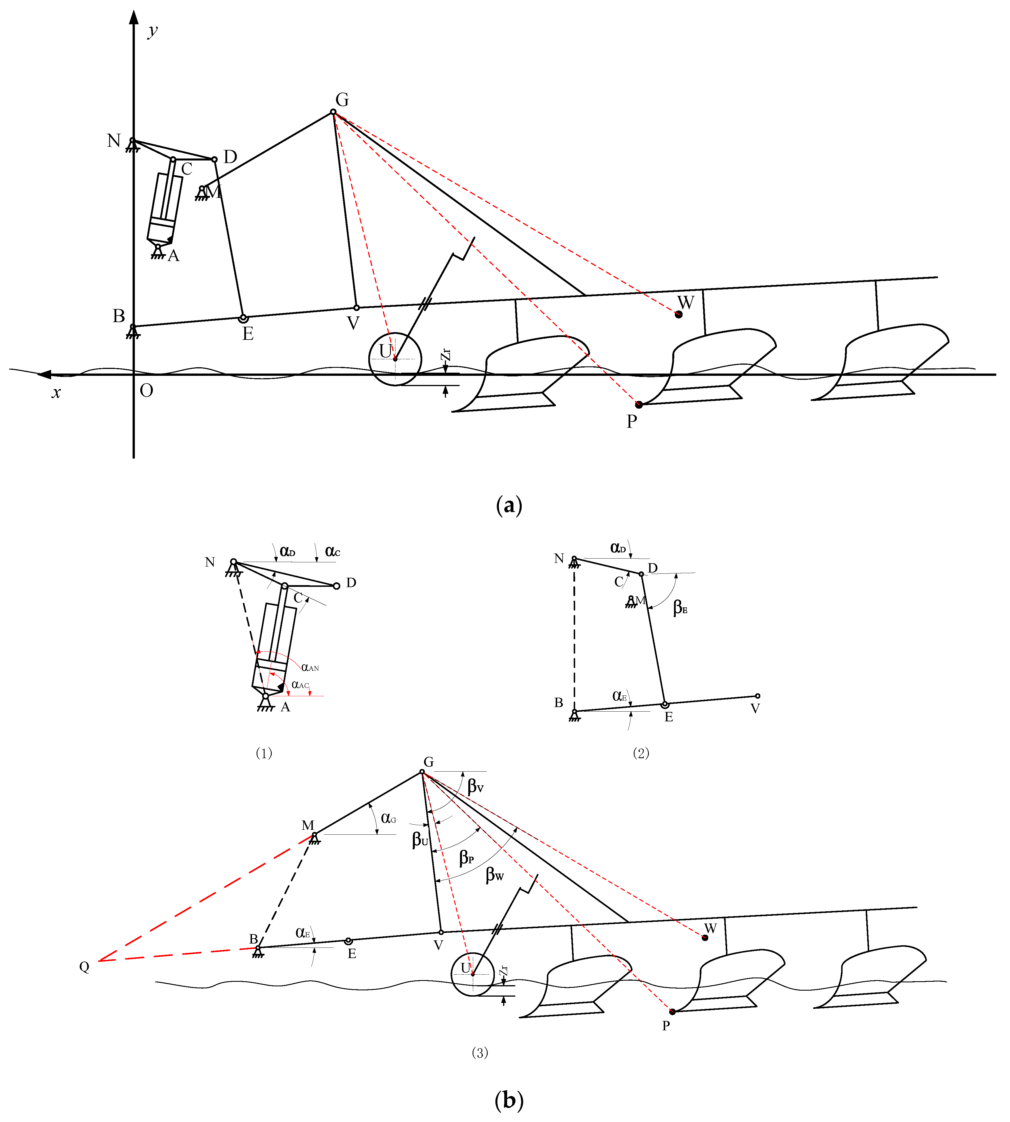
Figure 1. The structure of the tractor electronic hydraulic hitch: (a) whole part; (b) magnified part.
Applsci 10 03179 g001
Figure 2. Force analysis of plough.
Applsci 10 03179 g002
Figure 3. Simplified force analysis for tractor electronic hydraulic hitch:(a) force analysis of lifting arm; (b) force analysis of lower pull rod; (c) force analysis of plough gear.
Applsci 10 03179 g003
Figure 4. Pressure control block diagram of electro-hydraulic hitch with compensation link.
Applsci 10 03179 g004
Figure 5. Principle diagram of the adaptive fuzzy PID controller for pressure control.
Applsci 10 03179 g005
Figure 6. Input and output variable membership function: (a) Membership function of the input variables e, ec; (b) membership function of the output variables ΔKp, ΔKi, andΔKd.
Applsci 10 03179 g006
Figure 7. Adaptive fuzzy PID control simulation diagram.
Applsci 10 03179 g007
Figure 8. D-level road random time-domain simulation results.
Applsci 10 03179 g008
Figure 9. Step signal response curve: (a) Traditional PID; (b) Traditional PID with compensation correction and adaptive fuzzy PID with compensation correction.
Applsci 10 03179 g009
Figure 10. Fuzzy adaptive adjustment of Kp, Ki and Kd.
Applsci 10 03179 g010
Figure 11. Position coordinate curves of each point.
Applsci 10 03179 g011
Figure 12. Pressure control experimental platform for the tractor. (1) Pressure controller; (2) Host computer; (3) CAN card; (4) Power supply; (5) Pressure sensor; (6) Displacement sensor.
Applsci 10 03179 g012
Figure 13. Dynamic characteristics of pressure control: (a) Traditional PID; (b) Traditional PID with compensation correction; (c)Adaptive fuzzy PID with compensation correction.
Applsci 10 03179 g013
Table 1. Variables and domain.
VariablesBasic DomainQuantization DomainQuantization Factor
e[−1.5 1.5]{−3,−2,−1,0,1,2,3}2
ec[−15 15]{−3,−2,−1,0,1,2,3}0.2
Kp[−0.5 0.5]{−1,2/3,1/3, 0,1/3, 2/3,1}2
Ki[−1 1]{−1,2/3,1/3, 0,1/3, 2/3,1}1
Kd[−0.02 0.02]{−1,2/3,1/3, 0,1/3, 2/3,1}50
Table 2.Kp, ΔKi and ∆Kd fuzzy control rules.
eec
NBNMNSZPSPMPB
NBPB NB PSPB NB NSPM NM NBPM NM NBPS NS NBZ Z NMZ Z PS
NMPB NB PSPB NB NSPM NM NBPS NS NMPS NS NMZ Z NSNS Z Z
NSPM NB ZPM NM NSPM NS NMPS NS NMZ Z NSNS PS NSNS PS Z
ZPM NM ZPM NM NSPS NS NSZ Z NSNS PS NSNM PM NSNM PM Z
PSPS NM ZPS NS ZZ Z ZNS PS ZNS PS ZNM PM ZNM PB Z
PMPS Z PBZ Z NSNS PS PSNM PS PSNM PM PSNM PB PSNB PB PB
PBZ Z PBZ Z PMNM PS PMNM PM PMNM PM PSNB PB PSNB PB PB
Table 3. Performance comparison of control algorithms.
Input SignalCompensation CorrectionControllerOvershootResponse TimeStable Time
1.5 MPaNoTraditional PIDinstability1 sinstability
YesTraditional PID03.5 s3.5 s
YesAdaptive Fuzzy PID01 s1 s
Table 4. Control effect of different algorithms.
ControllerResponse TimePressure Range
Traditional PID2 s0.7~2.1 MPa
Traditional PID with compensation correction2.5 s1.2~1.7 MPa
Adaptive Fuzzy PID with compensation correction1.5 s1.3~1.6 MPa