Article

Selecting a Proper Microsphere to Combine Optical Trapping with Microsphere-Assisted Microscopy

1
University of Chinese Academy of Sciences, Beijing 100049, China
2
Institute of Optics and Electronics, Chinese Academy of Science, Chengdu 610209, Sichuan, China
*
Author to whom correspondence should be addressed.
Appl. Sci. 2020, 10(9), 3127; https://doi.org/10.3390/app10093127
Submission received: 13 April 2020 / Revised: 28 April 2020 / Accepted: 28 April 2020 / Published: 30 April 2020
(This article belongs to the Section Optics and Lasers)

Abstract

:
Microsphere-assisted microscopy serves as an effective super-resolution technique in biological observations and nanostructure detections, and optical trapping is widely used for the manipulation of small particles like microspheres. In this study, we focus on the selection of microsphere types for the combination of the optical trapping and the super-resolution microsphere-assisted microscopy, by considering the optical trapping performances and the super-resolution imaging ability of index-different microspheres in water simultaneously. Finally, the polystyrene (PS) sphere and the melamine formaldehyde (MF) sphere have been selected from four typical index-different microspheres normally used in microsphere-assisted microscopy. In experiments, the optically trapped PS/MF microsphere in water has been used to achieve super-resolution imaging of a 139 nm line-width silicon nanostructure grating under white light illumination. The image quality and the magnification factor are affected by the refractive index contrast between the microspheres and the immersion medium, and the difference of image quality is partly explained by the photonic nanojet. This work guides us in selecting proper microspheres, and also provides a label-free super-resolution imaging technique in many research fields.

1. Introduction

Optical microscopes have been widely used in medical sciences, biological observations and semiconductor detections. The resolution of conventional optical microscopes is restricted to around half of the illumination wavelength, due to the classical diffraction limit, which has greatly limited its applications in a variety of fields.
Several super-resolution imaging techniques were developed, including near-field scanning optical microscope [1], superoscillatory lens [2], solid immersion lens [3], fluorescence microscopy [4], and nanohole-structured mesoscale particles [5]. Besides these techniques, in 2011, an optical microscope aided by fused silica (SiO2) microspheres with low index ( n ~ 1.46 ) in air was used to achieve 100-nm-resolution imaging under white light illumination [6], and the observation power of microscopes was enhanced greatly. The microscopy assisted by index-different microspheres, typically the SiO2, polystyrene (PS), melamine formaldehyde (MF), barium titanate glass (BTG) microsphere, demonstrates the feasibility to realize super-resolution imaging of nanostructures and biological samples in different conditions [7,8,9,10,11,12]. Many other non-spherical and non-symmetrical particle-lens have also been investigated [13,14], and the main advantage of a sphere is that it can achieve ultra-sharp focusing of the incoming wave to generate extreme spatial field localization. The mechanism of the microsphere-assisted microscopy is still a heated topic [15,16,17]. Normally, microspheres are directly put onto the sample surface, which means the spheres are difficult to be controlled for imaging at a specific region. The lack of manipulation of microspheres restricts the applications greatly. To solve this problem, the position of microspheres is guided by fine glass micropipettes [18], scanning superlens microscopy [19], transparent solidified films [20], and remote-mode microsphere nano-imaging platform [21]. These techniques require direct contact with microspheres, and a non-contact optical manipulation technique of microspheres for imaging tends to be more attractive.
As the most typical non-contact optical manipulation technique of microparticles, optical trapping [22,23,24], also known as optical tweezers, has been widely used for the manipulation of microspheres for nano-fabrication and imaging applications. Mcleod at al. used Bessel beam laser trapping of 0.76 um PS microspheres to achieve near-field direct-write subwavelength nanopatterning, with minimum sizes of ~100 nm [25]. For imaging applications, the magnification property of the PS microsphere in liquid was investigated using optical tweezers [26]. An optically trapped SiO2 microsphere was utilized for surface imaging in air condition [27]. More recently, a localized plasmonic structural illumination microscopy, together with an optically trapped PS and TiO2 bead, in which fluorescent objects were used, was developed as a new microscopy technique with 7-11 times improvements of full width at half maximum (FWHM) compared with the result using only the objective [28]. In these research studies, especially for imaging applications, with optical tweezers, researchers investigated the imaging magnifying property of microsphere at visible frequencies or the combination of microsphere with other imaging techniques, and few super-resolution imaging results by a single-beam optically trapped microsphere are demonstrated under white light illumination. Meanwhile, less attention has been focused on the selection of microsphere types which affect both the optical trapping and the imaging performance.
The refractive index of the trapped particle in optical trapping is required to be larger than the index of immersion medium (normally the deionized water), which is compatible with the microsphere-assisted microscopy. However, microspheres of different types in the same immersion medium result in different optical trapping performances and varied imaging properties. In this research, we focus on the selection of microsphere types when combining optical trapping with microsphere-assisted microscopy. Choosing a proper type of microspheres is fairly important because the microsphere is not only the object of optical trapping, but also the one to be used to achieve super-resolution imaging. The properties of optical trapping and the imaging performances of microspheres are considered simultaneously to choose a proper microsphere, and finally the PS microsphere and the MF microsphere with moderate refractive index are selected. In experiments, the PS and MF microsphere with a 10-um diameter in water, trapped by a single laser beam, has been used to realize the super-resolution imaging of a silicon nanostructure grating (SNG) with 139-nm steps separated by a 139-nm gap under white light illumination. The magnification of the SNG image by the MF sphere is larger than that by the PS sphere. The SNG image by the MF sphere shows a better image quality than that of the PS sphere, which may be partly explained by the photonic nanojet (PNJ) [12,29,30,31]. The optically trapped PS/MF microsphere, maintaining the nanoscale observation power in water, can be used in many applications, especially in nanostructure observations.

2. The Selection of Microsphere Types

To select a proper type of microsphere for the combination of the optical trapping and the microsphere-assisted microscopy, we consider the optical trapping performances and the super-resolution imaging abilities of four typical microspheres in microsphere-assisted microscopy. The selected microsphere should be optically trapped by single-beam optical tweezers in water, and meanwhile it can realize super-resolution imaging under white light illumination.

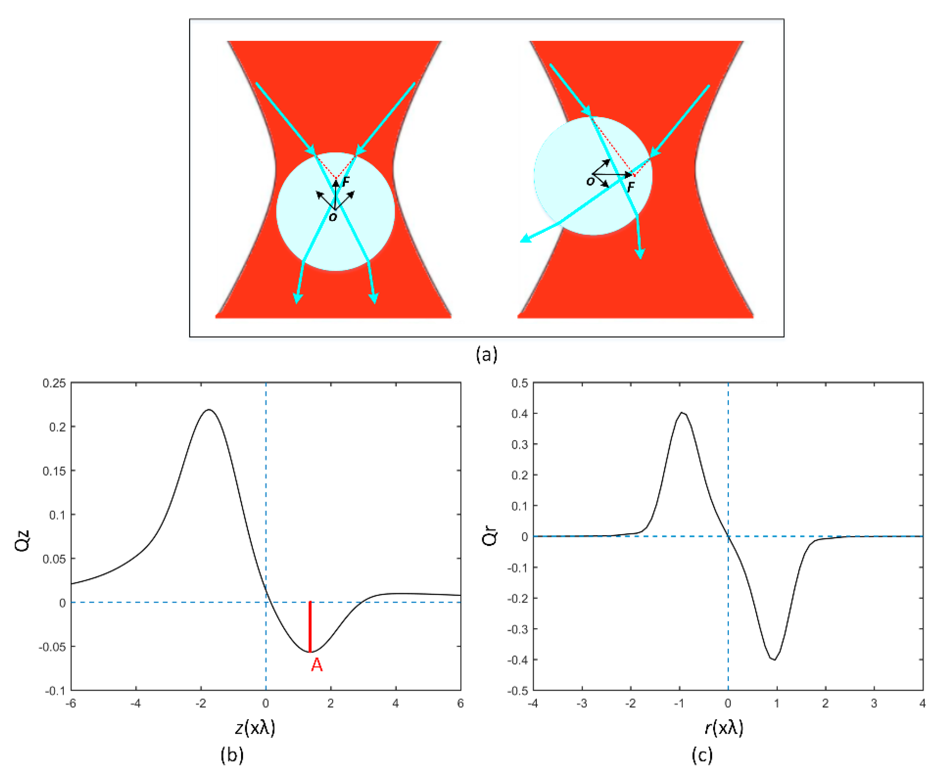
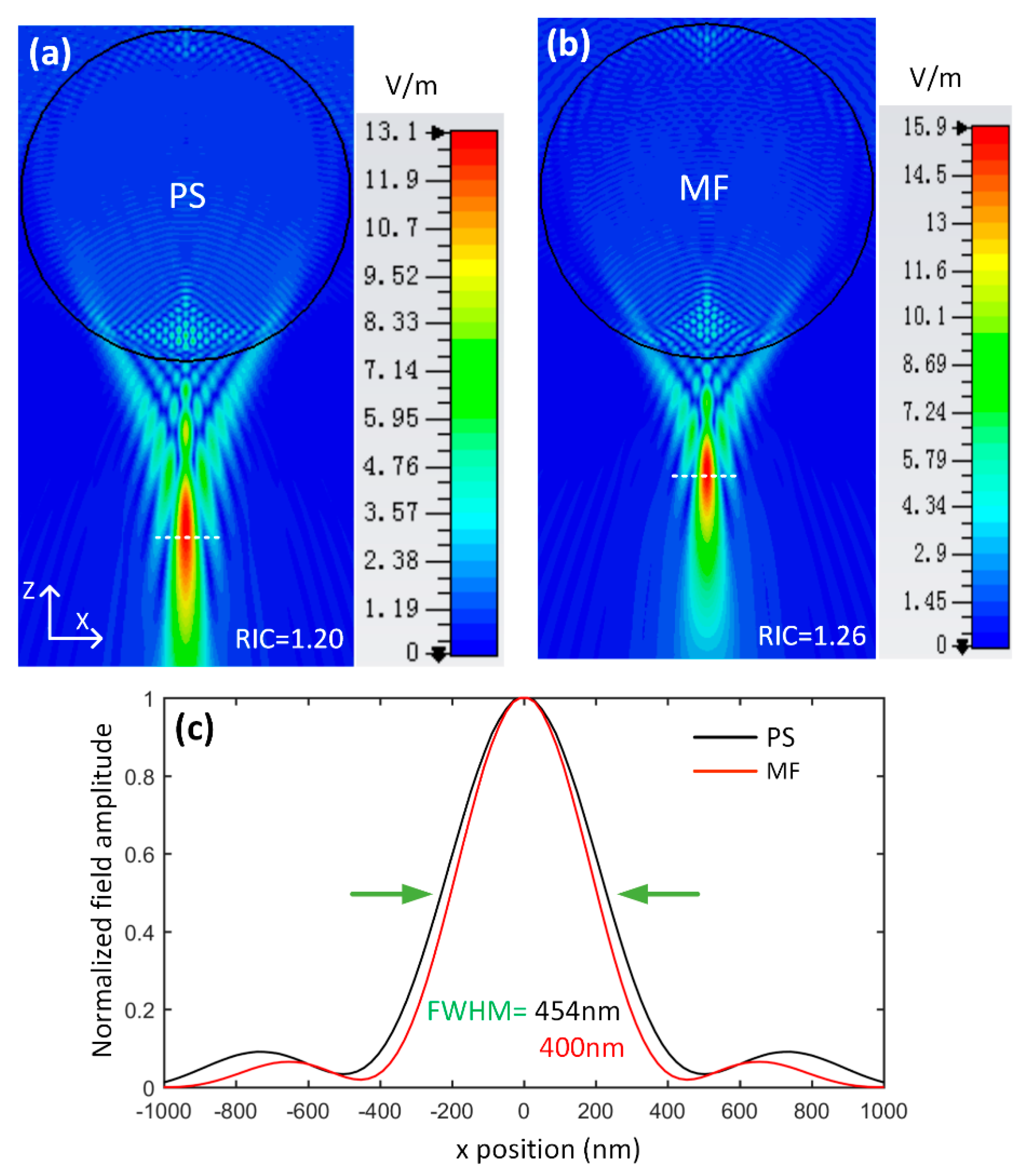
2.1. Optical Trapping Simulations

In simulations, we consider the trapping properties of index-different microspheres with varied diameters in single-beam optical tweezers. In stable optical tweezers, the gradient force, pointing to the trapping beam focus, is necessary to overcome the scattering force, which pushes the microsphere in the direction of beam propagation [22]. The T-matrix method is often used to calculate the forces acting on a particle illuminated by a focused beam [32], and an optical tweezers toolbox [33] has been developed to investigate the forces on particles in optical trapping. The typical Gaussian beam is commonly used as the trapping beam and it has a symmetric scattering profile for the radial displacement away from the beam axis for the microsphere. A scheme of optical trapping is shown in Figure 1a and the typical axial and radial force acting on a PS microsphere as a function of sphere position are shown in Figure 1b,c. The maximum reverse axial force A is important because it characterizes the strength of the trap. We focus on the maximum reverse axial force, which determines whether or not the microsphere can be trapped.
Next, we use the optical tweezers toolbox to calculate the forces as a function of two major parameters for optical trapping: the refractive index of the microsphere and the size of the microsphere. The results are useful when choosing a proper microsphere for the combination of optical trapping with microsphere-assisted microscopy. The dependence of the trap strength (the maximum reverse axial force) on refractive index and microsphere diameter is simulated to form the optical trapping landscapes, as shown in Figure 2. The range of refractive index n is 1.4–2.0. The diameter of microsphere in simulations is in a range of 1–15 um for an enough field of view (FOV) in microsphere-assisted microscopy, also for saving computational time. The numerical aperture (NA) of the objective used to focus the 1064 laser beam in water is set to 0.9 which is relatively low compared to that in the normal optical tweezers (NA 1.25 or 1.3), but such a NA is high enough in microsphere-assisted microscopy (normal NA 0.5~0.9). From the trapping landscapes, we can conclude that there is an upper limit of refractive index 1.8 for the used NA of 0.9 approximately, and a higher NA will increase the upper limit of the refractive index [34]. Microspheres with n < 1.6 can be trapped for diameters from 1 um into 15 um. For the high refractive indices ( n > 1.8 ), we can see that the microspheres cannot be trapped. With refractive indices between 1.6 and 1.8, most microspheres can be trapped, and the trapping efficiency decreases as the n increases. The trapping landscapes guide us when choosing a proper microsphere for the combination of optical tweezers and microscopy-assisted microscopy. For the typical microspheres used in microsphere-assisted microscopy like SiO2 ( n ~ 1.46 ), PS ( n ~ 1.59 ), MF ( n ~ 1.68 ) and BTG ( n ~ 1.9 ) spheres, these index-different spheres have different trapping performances. From the trapping landscapes with the used 0.9 NA, we know that the SiO2 and PS microsphere can be trapped stably for the n < 1.6 . For the MF sphere, except for some small spheres of particular diameters, we can also trap the MF sphere with single-beam optical tweezers. However, the BTG sphere cannot be trapped, because its high refractive index (above 1.8) increases the scattering force, which always pushes the sphere away from the focused laser spot, resulting in a failure in optical trapping.
Another impact factor in single-beam optical tweezers is the gravity of the microsphere. In normal optical tweezers with an inverted microscope, the gravitational force is in the opposite direction of the scattering force, which assists the gradient force to overcome the scattering force. However, in microsphere-assisted microscopy, the upright microscope is always utilized in imaging and the diameter of the used microsphere is normally larger than 5 um to get an enough FOV. When we use an upright microscope to combine the optical tweezers and microsphere-assisted microscopy, the relatively large gravity of the microsphere (if with a large diameter) will make the optical trapping difficult, because the gradient force is hard to overcome the scattering force and the gravitational force simultaneously. The optical trapping for a 25-um PS microsphere (density = 1.06 g/cm3) has been realized with an upright microscope [26], but few experiments were achieved for the BTG microsphere (density = 4.0 g/cm3) with a diameter larger than 10um by a single-beam optical tweezers, to the best of our knowledge. Even with a higher NA objective, the optical trapping for the BTG sphere is still a tough topic and high-index microspheres are always trapped by counterpropagating optical tweezers in which the scattering forces are canceled [35]. This means that the BTG sphere may not be suitable when combining the single-beam optical tweezers with microsphere-assisted microscopy. For a single-beam optical tweezers in water, the SiO2, PS, and MF microsphere can be optically trapped, and the BTG sphere is not the proper one for its high refractive index. Besides, the gravitational force of the sphere should be considered when selecting large spheres for optical trapping.

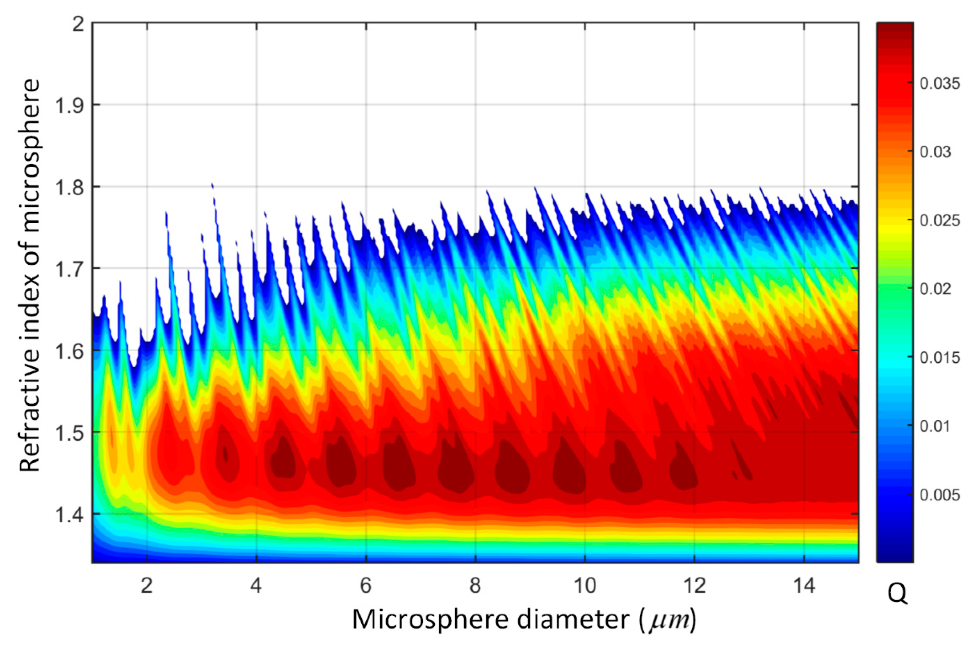
2.2. The Super-Resolution Imaging Ability of Index-Different Microspheres

Next, we consider the super-resolution imaging performances of index-different microspheres under white light illumination, including the SiO2, PS, MF and BTG microsphere. Many researchers have demonstrated that theses spheres in different immersion mediums maintain the discerning ability to achieve super-resolution imaging. The SiO2 sphere can realize super-resolution imaging in air or semi-immersing in ethanol droplet [6,7], but it loses such ability with full immersion in liquid [11]. Large PS spheres (diameters > 30 um) were used to overcome the diffraction limit in air condition [9], and it has also been demonstrated that the PS sphere with a 10 um diameter can discern a sub-diffraction nanopattern with a line width of 45 nm in water [10]. The MF sphere together with the Mirau interferometry has achieved label-free nano-3D imaging in air condition [8]. The super-resolution imaging of nanostructures was realized by fully immersing high-refractive-index BTG spheres in water [11,12]. Although the MF sphere in water is rarely used for super-resolution imaging, it should keep the super-resolution discerning ability, because its refractive index is between that in the PS and BTG sphere, which has been demonstrated by our next experimental results. In general, except for the SiO2 sphere, the PS, MF and BTG sphere can realize super-resolution imaging in water.
The optical trapping performances and the super-resolution imaging ability of these four types of microspheres in water are summarized in Table 1. Considering the optical trapping properties and the super-resolution imaging ability of index-different microspheres in water guides us in selecting a proper microsphere for the combination of the optical tweezers and the microsphere-assisted microscopy. From Table 1, the PS and MF sphere are selected, because that they can be optically trapped and they also maintain super-resolution imaging ability in water.

3. Experiments and Analysis

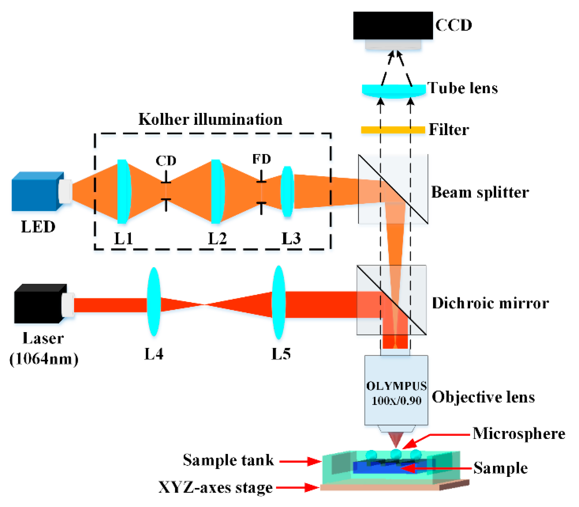
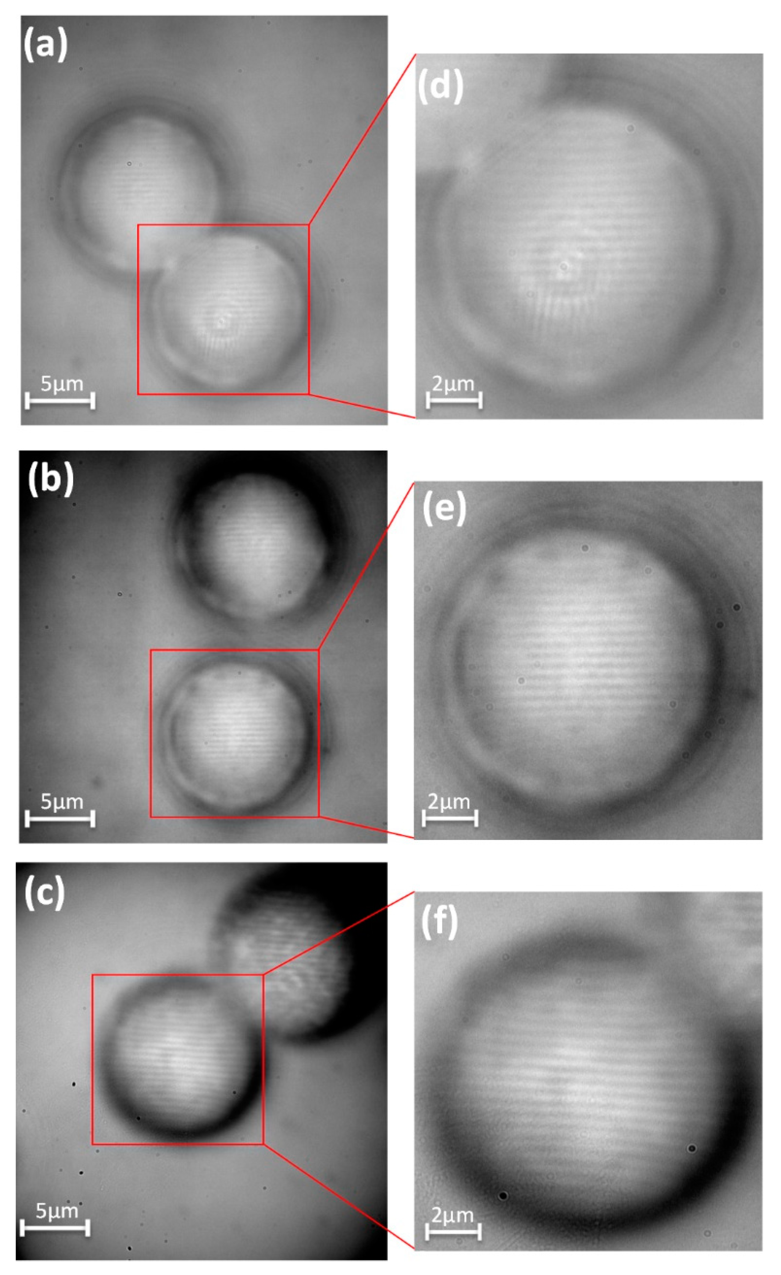
3.1. Experiment Setup

After selecting the PS and MF microsphere, in order to experimentally realize super-resolution imaging assisted by an optically trapped microsphere, we construct the experimental setup. The schematic of the optical system is shown in Figure 3, including the optical trapping system and imaging system with an upright objective lens. For the optical trapping part of the system, a continuous wave laser (wavelength of 1064 nm, 1.5 W, linear polarization) is used. Deionized water ( n m ~ 1.33 ) is used to immerse PS microspheres ( n ~ 1.59 , D~10 μm, BaseLine ChromTech Centre, Tianjin, China) and MF microspheres ( n ~ 1.68 , D~10 μm, Huacortek Microtek Co., Ltd., Wuhan, China). For the illumination part, Kölher illumination is conducted, in which a broadband LED (central wavelength of 600 nm) with an adjustable intensity is utilized, and we can adjust the condenser diaphragm (CD) and the field diaphragm (FD) to improve the image quality [36]. The objective (100×, NA = 0.9) is provided by Olympus Corporation, which under our conditions, gives a lateral resolution of 306 nm based on the equation 0.61 λ / N A / n m . A silicon nanostructure grating (SNG), consisting of 139 nm stripes with 139 nm separations is used as the sample which cannot be resolved by the objective. The imaging processing is conducted by a high-resolution CCD camera (acA2040, Basler). Firstly, we prepare the solution by diluting PS or MF spheres with deionized water in a proportion. Then, the sample is covered by a thin solution layer, and a few spheres are contained in this solution layer. The expanded laser beam is highly focused by the objective lens and then traps a sphere in the vicinity of its beam waist. The focused laser beam can be used to trap the sphere of interest. The optically trapped PS/MF microsphere is kept motionless and the position of the sample is adjusted by the 3-axis stage until the CCD captures magnified images of the measured surface in different positions. The optically trapped PS/MF microsphere is close enough to the sample and collects the sub-diffraction-limit frequencies of the sample. A short-pass filter (cut-off wavelength 800 nm) is used to eliminate the focused laser spot’s influence on imaging.

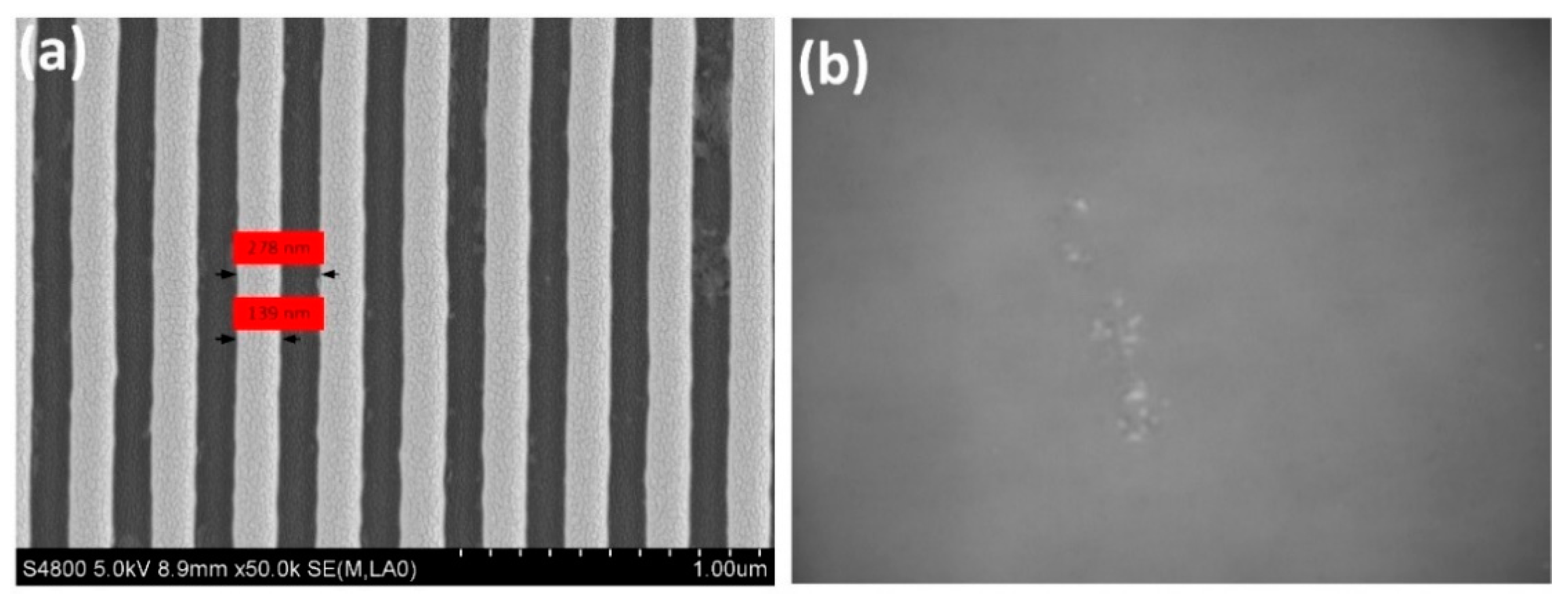
3.2. Results and Analysis

Figure 4a shows the scanning electron microscopy (SEM) image of the SNG with 139-nm steps separated by a 139-nm gap, which cannot be discerned by the objective (100×, NA = 0.9) under white light illumination, as seen in Figure 4b.
Figure 5a–c illustrate super-resolution images of the grating, through the optically trapped PS/MF microsphere. Figure 5a illustrates the super-resolution image by the trapped PS sphere without a filter, in which a highly focused laser spot is in the center of the sphere. The laser spot is harmful to the imaging processing and this negative effect can be eliminated by a short-pass filter, as seen in Figure 5b. The position of the SNG sample changes with the 3-axis stage; we can observe the area of interest. When moving the sample into different positions, only the trapped microsphere is nearly motionless, while the positions of other spheres are unpredictable, because of the movement of the sample and the Brownian motion, like in Figure 5b. Figure 5c shows the SNG structure image by the trapped MF sphere. Figure 5d–f show the enlarged view of section of Figure 5a–c, from which we can see the enlarged image of the grating, and the conventional optical microscope can capture the enlarged virtual image. The capability of microspheres to break the diffraction limit and magnify the nanostructure is related to the refractive index contrast (RIC, n / n m ) between the microspheres ( n ) and the immersion medium ( n m ) [37]. The RIC of the MF sphere in water is 1.26, which is larger than 1.20 of the PS sphere, and a better image quality by the MF sphere is obtained compared to that by the PS sphere, as illustrated in Figure 5e,f. A 2× lateral magnification is offered by the 10-μm PS sphere, while a 2.2× magnification for the 10-um MF sphere. The magnification factor is affected by the RIC, and normally a higher RIC leads to a larger magnification factor. The difference of image quality by these two spheres can be partially explained by the photonic nanojet (PNJ) [12,29,30,31], which is formed on the vicinity of the rear-surface of a microsphere with a narrow FWHM waist and extraordinarily high optical intensity. To study the PNJ properties of these two index-different microspheres in water, we perform the finite-difference time-domain (FDTD) numerical simulations using CST MWS software package (computer simulation technology). The simulation domain includes the 10-um-diamater sphere at the center and the immersion medium. The computational grid unit is a hexahedron of 5 nm size. Perfect matched layer (PML) is used for terminating the computation domain. For the incident wave, a linearly polarized wave with a free space wavelength 600 nm is propagating along the z-axis. The PS sphere (RIC = 1.20) and the MF sphere (RIC = 1.26) with the same diameter (10 um) is covered by water medium. Figure 6a,b show the electric field distributions of PNJs generated on the shadow sides of two spheres. Note that different RICs will produce different PNJs. We can see that that the MF sphere has a higher intensity of the PNJ due to the larger RIC, and it also has a narrower FWHM (400 nm) compared to that of PS sphere (454 nm), as illustrated in Figure 6c. A higher intensity and a narrower FWHM of PNJ may contribute to a better image quality, as demonstrated in [12,38]. We can expect that the use of higher-refractive-index microspheres is beneficial to a better experimental result under the condition of a stable optical trapping. We want to point out that there is a qualitative relation instead of quantitative relation between the simulation results and the experiments, and more advanced simulations need to be performed to reveal the imaging mechanism, which is beyond the scope of our focus in this research. These super-resolution experimental results, obtained by the trapped PS/MF sphere, have demonstrated that the optical trapping technique is quite compatible with the microsphere-assisted microscopy when selecting a proper microsphere.

4. Conclusions

In summary, we have focused on selecting proper microsphere types when combing optical trapping with super-resolution microsphere-assisted microscopy. The PS and MF microspheres have been selected after considering the optical trapping performances and the super-resolution imaging ability of different microspheres simultaneously. Then, an optically trapped PS/MF microsphere in water has been used to achieve super-resolution imaging of a 139-nm line-width SNG, which cannot be discerned by conventional microscopes, demonstrating the super-resolved power of PS/MF microspheres. The image quality and the magnification are affected by the refractive index contrast between the microsphere and the immersion medium, and the difference of image quality is partly explained by the photonic nanojet. Our procedure achieves an optical manipulation which does not require direct contact with microspheres, making it friendly to various samples. This work demonstrates the optical manipulation of PS/MF microspheres for super-resolution imaging under white light illumination, making it valuable in many applications, especially in nanostructure observations.

Author Contributions

X.L. did the simulations; X.L., S.H. and Y.T. designed the experiments; X.L. and Z.X. performed the experiments; X.L., J.L. and Y.H. wrote the paper; S.H. applied for the funding and managed the project. All authors have read and agreed to the published version of the manuscript.

Funding

This research was funded by the National Natural Science Foundation of China (61705232, 61675206, 61845201, 61604154, 61605212), the Instrument Developing Project of the Chinese Academy of Sciences (YZ201616), and in part by Sichuan science and technology program (18ZDZX0164, 2014GZ0113).

Conflicts of Interest

The authors declare no conflict of interest.

References

  1. Inouye, Y.; Kawata, S. Near-field scanning optical microscope with a metallic probe tip. Opt. Lett. 1994, 19, 159–161. [Google Scholar] [CrossRef]
  2. Rogers, E.T.F.; Lindberg, J.; Roy, T.; Savo, S.; Chad, J.E.; Dennis, M.R.; Zheludev, N.I. A super-oscillatory lens optical microscope for subwavelength imaging. Nat. Mater. 2012, 11, 432–435. [Google Scholar] [CrossRef]
  3. Terris, B.D.; Mamin, H.J.; Rugar, D.; Studenmund, W.R.; Kino, G.S. Near-field optical data storage using a solid immersion lens. Appl. Phys. Lett. 1994, 65, 388–390. [Google Scholar] [CrossRef]
  4. Betzig, E.; Patterson, G.H.; Sougrat, R.; Lindwasser, O.W.; Olenych, S.; Bonifacino, J.S.; Davidson, M.W.; Lippincott-Schwartz, J.; Hess, H.F. Imaging intracellular fluorescent proteins at nanometer resolution. Science 2006, 313, 1642. [Google Scholar] [CrossRef] [Green Version]
  5. Cao, Y.; Liu, Z.; Minin, O.V.; Minin, I.V. Deep Subwavelength-Scale Light Focusing and Confinement in Nanohole-Structured Mesoscale Dielectric Spheres. Nanomaterials 2019, 9, 186. [Google Scholar] [CrossRef] [Green Version]
  6. Wang, Z.; Guo, W.; Li, L.; Luk’yanchuk, B.; Khan, A.; Liu, Z.; Chen, Z.; Hong, M. Optical virtual imaging at 50 nm lateral resolution with a white-light nanoscope. Nat. Commun. 2011, 2, 218. [Google Scholar] [CrossRef] [Green Version]
  7. Zhou, Y.; Tang, Y.; Deng, Q.; Zhao, L.; Hu, S. Contrast enhancement of microsphere-assisted super-resolution imaging in dark-field microscopy. Appl. Phys. Express 2017, 10, 082501. [Google Scholar] [CrossRef]
  8. Kassamakov, I.; Lecler, S.; Nolvi, A.; Leong-Hoï, A.; Montgomery, P.; Hæggström, E. 3d super-resolution optical profiling using microsphere enhanced mirau interferometry. Sci. Rep. 2017, 7, 3683. [Google Scholar] [CrossRef] [PubMed] [Green Version]
  9. Lee, S.; Li, L.; Ben-Aryeh, Y.; Wang, Z.; Guo, W. Overcoming the diffraction limit induced by microsphere optical nanoscopy. J. Opt. 2013, 15, 125710. [Google Scholar] [CrossRef] [Green Version]
  10. Li, J.; Liu, W.; Li, T.; Rozen, I.; Zhao, J.; Bahari, B.; Kante, B.; Wang, J. Swimming microrobot optical nanoscopy. Nano Lett. 2016, 16, 6604–6609. [Google Scholar] [CrossRef] [PubMed]
  11. Darafsheh, A.; Walsh, G.F.; Dal Negro, L.; Astratov, V.N. Optical super-resolution by high-index liquid-immersed microspheres. Appl. Phys. Lett. 2012, 101, 141128. [Google Scholar] [CrossRef] [Green Version]
  12. Darafsheh, A. Influence of the background medium on imaging performance of microsphere-assisted super-resolution microscopy. Opt. Lett. 2017, 42, 735–738. [Google Scholar] [CrossRef] [PubMed]
  13. Minin, I.V.; Minin, O.V.; Geints, Y.E. Localized EM and photonic jets from non-spherical and non-symmetrical dielectric mesoscale objects: Brief review. Ann. Der Phys. 2015, 527, 491–497. [Google Scholar] [CrossRef] [Green Version]
  14. Pacheco-Peña, V.; Beruete, M.; Minin, I.V.; Minin, O.V. Terajets produced by dielectric cuboids. Appl. Phys. Lett. 2014, 105, 084102. [Google Scholar] [CrossRef] [Green Version]
  15. Chen, L.; Zhou, Y.; Li, Y.; Hong, M. Microsphere enhanced optical imaging and patterning: From physics to applications. Appl. Phys. Rev. 2019, 6, 021304. [Google Scholar] [CrossRef]
  16. Wang, Z.; Luk’yanchuk, B. Super-resolution imaging and microscopy by dielectric particle-lenses. In Label-Free Super-Resolution Microscopy; Astratov, V., Ed.; Springer International Publishing: Cham, Switzerland, 2019; pp. 371–406. [Google Scholar]
  17. Ben-Aryeh, Y. Increase of resolution by use of microspheres related to complex snell’s law. J. Opt. Soc. Am. A 2016, 33, 2284–2288. [Google Scholar] [CrossRef]
  18. Krivitsky, L.A.; Wang, J.J.; Wang, Z.; Luk’yanchuk, B. Locomotion of microspheres for super-resolution imaging. Sci. Rep. 2013, 3, 3501. [Google Scholar] [CrossRef] [Green Version]
  19. Wang, F.; Liu, L.; Yu, H.; Wen, Y.; Yu, P.; Liu, Z.; Wang, Y.; Li, W.J. Scanning superlens microscopy for non-invasive large field-of-view visible light nanoscale imaging. Nat. Commun. 2016, 7, 13748. [Google Scholar] [CrossRef]
  20. Darafsheh, A.; Guardiola, C.; Palovcak, A.; Finlay, J.C.; Cárabe, A. Optical super-resolution imaging by high-index microspheres embedded in elastomers. Opt. Lett. 2015, 40, 5–8. [Google Scholar] [CrossRef]
  21. Lianwei, C.; Yan, Z.; Mengxue, W.; Minghui, H. Remote-mode microsphere nano-imaging: New boundaries for optical microscopes. Opto Electron. Adv. 2018, 1, 170001. [Google Scholar]
  22. Ashkin, A.; Dziedzic, J.M.; Bjorkholm, J.E.; Chu, S. Observation of a single-beam gradient force optical trap for dielectric particles. Opt. Lett. 1986, 11, 288–290. [Google Scholar] [CrossRef] [Green Version]
  23. Bouloumis, T.D.; Nic Chormaic, S. From Far-Field to Near-Field Micro- and Nanoparticle Optical Trapping. Appl. Sci. 2020, 10, 1375. [Google Scholar] [CrossRef] [Green Version]
  24. Minin, I.V.; Minin, O.V.; Cao, Y.; Liu, Z.; Geints, Y.E.; Karabchevsky, A. Optical vacuum cleaner by optomechanical manipulation of nanoparticles using nanostructured mesoscale dielectric cuboid. Sci. Rep. 2019, 9, 12748. [Google Scholar] [CrossRef] [PubMed] [Green Version]
  25. McLeod, E.; Arnold, C.B. Subwavelength direct-write nanopatterning using optically trapped microspheres. Nat. Nanotechnol. 2008, 3, 413–417. [Google Scholar] [CrossRef] [PubMed]
  26. Sasaki, M.; Kurosawa, T.; Hane, K. Micro-objective manipulated with optical tweezers. Appl. Phys. Lett. 1997, 70, 785–787. [Google Scholar] [CrossRef]
  27. Michihata, M.; Kim, J.; Takahashi, S.; Takamasu, K.; Mizutani, Y.; Takaya, Y. Surface imaging technique by an optically trapped microsphere in air condition. Nanomanufacturing Metrol. 2018, 1, 32–38. [Google Scholar] [CrossRef]
  28. Bezryadina, A.; Li, J.; Zhao, J.; Kothambawala, A.; Ponsetto, J.; Huang, E.; Wang, J.; Liu, Z. Localized plasmonic structured illumination microscopy with an optically trapped microlens. Nanoscale 2017, 9, 14907–14912. [Google Scholar] [CrossRef]
  29. Yang, H.; Trouillon, R.l.; Huszka, G.; Gijs, M.A.M. Super-resolution imaging of a dielectric microsphere is governed by the waist of its photonic nanojet. Nano Lett. 2016, 16, 4862–4870. [Google Scholar] [CrossRef]
  30. Yang, H.; Moullan, N.; Auwerx, J.; Gijs, M.A.M. Super-resolution biological microscopy using virtual imaging by a microsphere nanoscope. Small 2014, 10, 1712–1718. [Google Scholar] [CrossRef]
  31. Luk’yanchuk, B.S.; Paniagua-Domínguez, R.n.; Minin, I.; Minin, O.; Wang, Z. Refractive index less than two: Photonic nanojets yesterday, today and tomorrow [invited]. Opt. Mater. Express 2017, 7, 1820–1847. [Google Scholar] [CrossRef]
  32. Nieminen, T.A.; Loke, V.L.Y.; Stilgoe, A.B.; Heckenberg, N.R.; Rubinsztein-Dunlop, H. T-matrix method for modelling optical tweezers. J. Mod. Opt. 2011, 58, 528–544. [Google Scholar] [CrossRef]
  33. Nieminen, T.A.; Loke, V.L.Y.; Stilgoe, A.B.; Knöner, G.; Brańczyk, A.M.; Heckenberg, N.R.; Rubinsztein-Dunlop, H. Optical tweezers computational toolbox. J. Opt. A: Pure Appl. Opt. 2007, 9, S196–S203. [Google Scholar] [CrossRef] [Green Version]
  34. Sun, B.; Grier, D.G. The effect of mie resonances on trapping in optical tweezers: Comment. Opt. Express 2009, 17, 2658–2660. [Google Scholar] [CrossRef] [PubMed]
  35. Van der Horst, A.; van Oostrum, P.D.J.; Moroz, A.; van Blaaderen, A.; Dogterom, M. High trapping forces for high-refractive index particles trapped in dynamic arrays of counterpropagating optical tweezers. Appl. Opt. 2008, 47, 3196–3202. [Google Scholar] [CrossRef] [Green Version]
  36. Perrin, S.; Li, H.; Leong-Hoi, A.; Lecler, S.; Montgomery, P. Illumination conditions in microsphere-assisted microscopy. J. Microsc. 2019, 274, 69–75. [Google Scholar] [CrossRef]
  37. Li, L.; Guo, W.; Yan, Y.; Lee, S.; Wang, T. Label-free super-resolution imaging of adenoviruses by submerged microsphere optical nanoscopy. Light: Sci. Appl. 2013, 2, e104. [Google Scholar] [CrossRef] [Green Version]
  38. Hou, B.; Zhang, L. Liquid microdroplet as an optical component to achieve imaging of 100 nm nanostructures on a far-field microscope. J. Opt. 2018, 20, 055606. [Google Scholar] [CrossRef]
Figure 1. Force on a polystyrene (PS) sphere in a Gaussian beam trap. The PS sphere has a radius of 1 λ , and has a relative refractive index of n r e l = 1.59 / 1.33 = 1.20 , trapped at 1064 nm, using an objective with numerical aperture of 1.02. (a) A scheme of optical trapping, in which the sphere in a focused Gaussian beam is dragged toward a region of high intensity. (b) The axial trapping efficiency as a function of axial displacement and (c) the transverse trapping efficiency as a function of transverse displacement from the equilibrium point. The maximum reverse axial force A is shown in (b) and it characterizes the strength of the trap.
Applsci 10 03127 g001
Figure 2. Trapping landscapes. The maximum reverse axial force in the direction of beam propagation is shown, in terms of the trapping efficiency Q as a function of refractive index and microsphere diameter. The trapping efficiency Q can be converted to the maximum reverse axial force by multiplying by n m P / c , where n m is the refractive index of the immersion medium, P is the beam power at the focus, and c is the light speed in free space. An objective with NA = 0.9 is used to focused the 1064 nm trapping beam, and the water is used as the immersion medium in simulations. The trapping landscape can be divided into two portions approximately. In the lower portion, we can see that microspheres with relatively low refractive index ( n < 1.8 ) can be trapped. In the upper portion, microspheres with high refractive index ( n > 1.8 ) are hard to be trapped with the used NA.
Applsci 10 03127 g002
Figure 3. Schematic of the constructed optical system. The red path represents the optical trapping system and the tangerine path serves as the imaging part. The same objective lens is used for both the trapping process and the observation.
Applsci 10 03127 g003
Figure 4. (a) The SEM image of the silicon nanostructure grating (SNG) with a period of 278 nm and a 139-nm line-width. (b) The imaging of the SNG without microspheres, from which we cannot visualize the grating structure due to the diffraction limit.
Applsci 10 03127 g004
Figure 5. Super-resolution images of the SNG using an optically trapped 10-μm-diameter PS/MF sphere. (a) The SNG image assisted by an optically trapped 10-μm-diameter PS sphere without a filter, in which the focused laser spot affects the imaging. (b) The SNG image by the trapped PS phere, in which a short-pass filter is used to eliminate the focused laser spot, and the un-trapped PS sphere moves away from the trapped one when moving the sample stage. (c) The SNG image assisted by a trapped 10-um MF sphere. (df) zoom-in of (ac), respectively. With the trapped PS/MF sphere, we can visualize the sub-diffraction-limited grating structures, and the image by the MF sphere (f) shows a better imaging quality compared to that by the PS sphere (e). The sphere in the red frame is optically trapped and is kept motionless when moving the sample.
Applsci 10 03127 g005
Figure 6. Numerical simulations of electric field distributions around a 10-μm sphere, with different refractive indices in water medium: (a) PS sphere, refractive index contrast (RIC) = 1.20, (b) MF sphere, RIC = 1.26. (c) Normalized intensity in the full width at half maximum (FWHM) plane for the PS and MF sphere. The white dotted line represents the location of the FWHM plane.
Applsci 10 03127 g006
Table 1. Optical trapping performances and super-resolution ability of four microspheres in water.
MicrosphereOptical Trapping Super-Resolution Ability
SiO2x
PS
Melamine formaldehyde (MF)
Barium titanate glass (BTG)x

