Article

Buckling Analysis of Interspersed Railway Tracks

by
Chayut Ngamkhanong
,
Chuah Ming Wey
and
Sakdirat Kaewunruen
*
Department of Civil Engineering, School of Engineering, The University of Birmingham, Birmingham B15 2TT, UK
*
Author to whom correspondence should be addressed.
Appl. Sci. 2020, 10(9), 3091; https://doi.org/10.3390/app10093091
Submission received: 11 April 2020 / Revised: 22 April 2020 / Accepted: 26 April 2020 / Published: 29 April 2020
(This article belongs to the Special Issue Extreme Sciences and Engineering Ⅱ)

Abstract

:

Featured Application

The new findings highlight for the first time the buckling phenomena of interspersed railway tracks, which are usually adopted during railway transformations from timber to concrete sleepered tracks in real-life practices globally. The novel in-depth insight unprecedentedly instigates vulnerability and resilience of traditional and interspersed railway track systems exposed to extreme weather conditions. The method in the article can be used (not limited to) as an indicative reference for innovative design and maintenance for stability and misalignment management of ballasted railway tracks.

Abstract

Nowadays, timber sleepers are still used for ballasted railway tracks to carry passengers and transport goods. However, the process of natural decay causes the problem of timber sleeper degradation over time. A temporary “interspersed” approach is used to replace rotten timbers with concrete sleepers. This implementation has several inadequacies, as interspersed railway tracks have inconsistent stiffness and experience significant deterioration over the years. Increased heat due to the change in the global climate can induce a compression force in the continuous welded rail (CWR), leading to a change in track geometry called “track buckling”. A literature review shows that track buckling on plain tracks has been widely studied. However, the buckling of interspersed tracks has not been fully studied. This study presents 3D finite element modelling of interspersed railway tracks subjected to temperature change. The effect of the boundary conditions on the buckling shape is considered. The obtained results show that the interspersed approach may reduce the likelihood of track buckling. This study is the world’s first to investigate the buckling behaviour of interspersed railway tracks. The insight into interspersed railway tracks derived from this study will underpin the life cycle design, maintenance, and construction strategies related to the use of concrete sleepers as spot replacement sleepers in ageing railway track systems. The outcome of this study will help track engineers to improve the inspection of the lateral stiffness of interspersed tracks in areas prone to extreme temperature.

1. Introduction

Timber railway sleepers have often been used as railway sleepers worldwide [1,2]. Such sleepers are expected to serve for about 15 to 20 service years, but the strength and serviceability of timber railway sleepers degrade over time. At present, the limited availability of reliable and high-quality timbers, and restrictions on deforestation, have inspired the world to explore more alternatives for the ageing timber sleepers [3,4,5]. Most countries have adopted concrete railway sleepers as the replacement. It is also important to note that the main function of “spot replacement” railway tracks (also called “interspersed railway tracks”) is to enhance the performance of the lower-class tracks with low operational speed. These can be found in various countries such as Australia, Japan, the United Kingdom, and the United States [2,3,4].
Although a partial replacement of aged, rotten sleepers is obviously more economical than complete track renewal or reconstruction, interspersed tracks have some drawbacks. According to open literature and industry knowledge, this practice could consequently undermine the existing ground foundations and also induce inconsistent local stiffness problems in the rail track system [5,6,7,8,9] and different track decay rates [10,11,12,13,14,15,16,17]. It is clear that the long-term performance of interspersed tracks can be impaired. Studies of interspersed tracks have been carried out [18,19,20,21]. Moving train loads were applied to interspersed tracks to study the vertical dynamic responses. It was observed that the replacement of timber sleepers by concrete tends to increase the deterioration rate of the railway track, as uplift behaviour occurs [21]. The condition of deteriorated interspersed track is presented in Figure 1.
With the increase of global temperature, track buckling is a serious concern and has been found around the world [22,23,24]. Summer heat can significantly increase the rail temperature and cause the rail to expand, leading to a buildup of axial compression force in continuous welded rail (CWR). Although CWR provides a smooth ride and has a lower maintenance cost, it still suffers from drawbacks as the track tends to buckle easily when the rail temperature reaches a certain limit [25,26,27,28]. Based on the evidence [29,30,31,32], track buckling can cause derailment and cause huge loss of assets and passengers’ lives. Moreover, for ballastless tracks, extreme temperatures may cause problems in the rail–structure interface by adding longitudinal stress in the rail and structure. It is noted that the additional stress on a structure should be controlled and not exceed the admissible stress capacity [33,34,35]. Although track buckling has been widely investigated [36,37,38,39,40,41,42,43], interspersed tracks and their inconsistency have never been taken into account. It is interesting to note that timber and concrete sleepers have different properties and geometry, leading to inconsistency in resistance when it comes to interspersed tracks. Buckling resistance mainly depends on the specific type of sleeper, ballast, fastening system, etc. The sleeper type plays a role in track lateral resistance, especially on the friction base at the contact area between the ballast and sleeper [44,45,46]. Previous studies have shown that different types of sleepers provide different values of lateral resistance and the contribution of lateral resistance of each part is due to their properties [47,48,49,50]. It was found that the lateral resistance of timber sleepers is about 60–80% that of concrete sleepers. Moreover, maintenance activities, such as ballast tamping, stone blowing, and sleeper replacement, can significantly reduce the compaction of ballast, leading to a reduction in the lateral resistance [49,50]. Furthermore, torsional resistance also depends on the fastener and sleeper type. It is interesting to note that the conservative torsional stiffness value for timber is greater than that for concrete. Importantly, the replacement of sleepers should be done carefully since it may severely reduce track lateral stiffness.
This study aims at investigating the buckling behaviour of interspersed railway tracks due to thermal loads in three-dimensional space. All four types of interspersed railway tracks were constructed previously, and their results are compared to those of a plain concrete track. The original model was validated previously using track vertical response under train loads against the laboratory data and against experimental and multibody train track simulation results [18,19,20]. The model was extended for buckling analysis and validated against analytical solutions. Eigenvalue analysis is used to analyse the buckling temperature and buckling shape at the bifurcation point of railway tracks based on the assumption of a linear property. It is noted that this method can provide accurate results at the maximum and help to save computational time. This study is the world’s first to present the buckling behaviour of interspersed railway tracks, and this will help track engineers to improve track buckling mitigation methods at spot replacements.

2. Methodology

2.1. Finite Element Modelling

The buckling analysis was conducted using a three-dimensional finite element model. The finite element analysis software called “STRAND7” [51] was used to carry out the analysis, and five different types of railway tracks were used. A linear buckling analysis solver based on eigenvalue analysis was used. The finite element models of railway tracks were validated against previous numerical and experimental modal parameters [19,52]. The rails and sleepers were modelled as beam elements. The two-dimensional Timoshenko beam model was used for the beam elements as it was found to be a suitable option [53]. The validated sleeper model with spring support considering compression only was replicated to construct a track model. The support spring value was tuned to represent the whole substructure layer for the railway track. The rail pads and fastening systems were simulated using a series of spring–dashpot elements. The stiffness and damping values of high-density polyethylene (HDPE) pads were assigned to the spring–dashpot elements based on experimental results [54]. As for the ballast, the tensionless spring support option correctly represents the ballast characteristics in real tracks since this attribute allows the beam to lift over the support, while the tensile supporting stiffness is omitted. Meanwhile, the lateral spring is applied at one sleeper end, and the resistance value can represent the overall ballast lateral resistance as a tensionless spring.
In this study, four types of commonly adopted interspersed railway tracks and plain concrete track were adopted, as shown in Figure 2. They are identified as plain timber railway track (“1 in 1”) and “1 in 2”, “1 in 3”, and “1 in 4” interspersed railway tracks. By definition, “1 in 2” entails the establishment of alternating concrete and timber railway sleepers on the railway tracks, while “1 in 3” refers to another type of interspersed track where one concrete sleeper is seated alongside every two timber sleepers. Similarly, the “1 in 4” configuration indicates that one concrete sleeper is present for every three timber sleepers along the railway track. It should be noted that a concrete sleeper track was also compared with the timber and interspersed tracks in this study.

2.2. Material Properties and Boundary Conditions

It should be noted that the ballast lateral resistance, which is a major factor to resist track buckling, was based on the initial stiffness within the linear elastic zone obtained from single sleeper (tie) pull/push tests (STPT) that have been carried out by many researchers [45,46,47,48]. The effects of ballast, such as shoulder height, shoulder width, crib height, ballast depth, ballast compaction, etc., play a significant role in the resistance in the lateral plane. Assuming the same ballast geometry, the differences between the lateral resistances of concrete and timber sleepers depend on the sleeper–ballast contact and friction, which are mainly affected by the sleeper shape, weight, and geometry. Hence, track lateral resistance mainly comes from ballast–sleeper interaction. It is noted that the three main contributions are sleeper side friction (crib), sleeper bottom friction, and end or ballast shoulder restraint. For these reasons, inconsistency in the lateral resistance of interspersed tracks needs to be considered for buckling analysis. Some researchers have studied the difference in lateral resistance between timber sleepers and concrete sleepers. The typical values of timber sleeper peak resistance are lower than those of concrete by about 500 lbs/sleeper [44]. Others have found that the lateral resistance ratio between timber track and concrete track is about 0.6–0.8 [41].
In this study, it was assumed that the ballast lateral resistance of timber sleepers is about 60% that of concrete sleepers as this represents the worst-case scenario for the lateral resistance of sleepers. The parameters used for lateral resistance were calculated from the slope of the load–deflection relationship obtained in the linear elastic zone. Apart from lateral resistance, other factors influence the buckling strength of railway tracks, such as torsional resistance, track curvature, track misalignment, etc. The torsional resistance is provided by the sleeper and rail connections via fastening systems. The main function of fastening systems is to resist rail creep and provide torsional and translational resistances to maintain rail gauge and track stability [42]. According to previous experiments, the resistance values for rail fastenings to timber sleepers are higher than those for concrete sleepers [27]. The different fastening systems and types of sleepers were tested [39]. It was found that the sleeper types do not influence torsional resistance, while the fastening systems for timber sleepers are much stronger than those for concrete, resulting in higher torsional resistance. Nominal values of torsional resistance per fastener were proposed [27]. It should be noted that the torsional stiffness of the fastening systems for concrete sleepers is about 40–70% that for timber sleepers [26,27]. In this study, assumptions on the values of lateral and torsional resistance were drawn based on previous testing. The material properties are presented in Table 1. For the worst-case scenario, it was assumed that the lateral resistance, represented by the spring at one sleeper end, of the span of timber sleepers is 60% that of concrete sleepers, while the torsional resistance of the fastening on timber sleepers is 2.5 times that of concrete sleepers.
In reality, track buckling can be often found in symmetrical (Figure 3a) or antisymmetrical (Figure 3b) shapes. Generally, there are two regions, consisting of buckled regions and adjoining regions. The buckled zone is the zone of change in shape of the track geometry in the lateral plane, while the rails are deformed longitudinally in the adjoining zone. In the analytical solutions for track buckling [37], the track consists of a buckled region ( 0 x l ) and adjoining region ( l x l 0 ) which has a length of a. Subscripts 1, 2, and 0 represent the buckled regions 1 and 2 and the area beyond the adjoining regions, respectively. The differential equations are solved to get the resulting equations. For the antisymmetrical buckling shape, the governing equations are identical to those derived for the symmetrical buckling shape except for the boundary condition at mid-track.
It should be noted that the buckling shape and buckled region in the actual track can be changed due to changes in track constraints or boundary conditions. In this study, 100 m, 60 m, and 30 m tracks were investigated to study the effect of track length and unconstrained length, which is the length in the buckled region. It should be noted that the buckling length is normally between 10 m and 30 m, so an unconstrained length of 30 m was chosen, while beyond this length was considered the adjoining zone. According to the analytical solution [37], the unconstrained length and boundary conditions have a slight effect on buckling temperature but play a role in buckling shape. In this study, fixed supports were applied at both ends. To investigate the adjoining zone ( l x l 0 ) after buckling, roller supports, which allow the rail to move in a longitudinal direction, were applied to the rails. The buckled zone ( 0 x l ) is a weaker area that allows the track to move laterally and be buckled so that it represents the buckling length of the track.

2.3. Linear Eigenvalue Analysis

In this study, linear buckling analysis was used to predict the buckling temperature. Firstly, boundary conditions were considered to study the lengths of the buckling and adjoining zones. After preliminary study on the buckling zone, it was found that the boundary condition has a slight effect on the buckling temperature but plays a significant role in the buckling shape. To reduce the time consumption, only buckling temperature was studied using linear eigenvalue analysis.
Importantly, the buckling regime is mostly in the range between the maximum and minimum buckling temperatures, as shown in Figure 4. It is noted that the maximum buckling temperature (TBmax) is the inflection path, where the pre-buckling stage becomes the post-buckling stage, also known as the “bifurcation or critical temperature”. The minimum buckling temperature (TBmin) is the lower bound which can buckle the track if sufficient energy is supplied. It can also be defined as a safe temperature since the track cannot buckle if it experiences heat below this temperature. It should be noted that only the bifurcation temperature, where the track suddenly buckles and becomes unstable, was evaluated in this study.
It is important to note that eigen buckling analysis predicts the presence of the bifurcation point at which the primary load–deflection path is bifurcated by a secondary load–deflection path, as shown in Figure 5, and it can occur at more than one equilibrium position at this point [51,55,56]. It is noted that, after buckling, the post-buckling state does not follow the primary path. In this stage, the secondary slope can be either positive (post-buckling strength) or negative (simply collapse). The governing equation used for calculating the buckling temperature and corresponding buckling shapes is shown in Equation (1).
| K + λ K g | = 0
This equation is equivalent to the eigenvalue solution as shown in Equation (2):
K x = λ K g x
where K is the global stiffness matrix, x is buckling mode vectors, λ is the buckling load factor (BLF), and K g is a global geometric stiffness matrix known as the initial stress stiffness matrix depending on the stress level of the element. It is noted that the element force vector at each state changes the geometric stiffness of the element.
It is important to note that the buckling load factor (BLF) is an indicator of the safety factor (FOS) against buckling or the ratio of the buckling load to the currently applied loads. By using Equation (2), the BLFs are calculated and then multiplied by the applied temperature to get the buckling temperature. In this study, 100 °C was applied to the whole system. It should be noted that buckling is predicted when the applied thermal loads are higher than the estimated critical loads (BLF < 1). On the other hand, the track is not buckled under the applied temperature when the BLF is beyond 1. However, linear eigenvalue analysis can still calculate the buckling temperature by extrapolating to reach the buckling temperature, even though the possible buckling temperature is higher than the applied temperature.

2.4. Model Validation

The models used in this study were previously used to analyse the vertical responses of interspersed tracks under moving train loads. The results were validated using experimental parameters, field data, and previous laboratory results [18,19,20,21,22]. However, interspersed railway track buckling has never been investigated, so the validation of a plain concrete sleeper track was considered. It is noted that a straight ballasted track with only concrete sleepers was considered for validation. Lateral stiffness of 200 N/mm and torsional stiffness of 75 kNm/rad were considered to compare with the previous studies as these values represent similar track conditions and properties. The result was validated against two different previous analytical solutions and Finite Element Method (FEM). The analytical solutions were based on the principle of the virtual displacement equation and bending beam theory. The results were solved by assuming the buckling shape and applying the chosen track parameters to the equation. The buckling temperature was then calculated from the corresponding value of axial force [36,38]. The previous finite element approach used an indirect method combining two rails into one idealised continuous beam with four springs representing the ballast and fastening with spacing of 1 m along the beam [43]. The average temperature increase of the previous analytical solutions and finite element analysis result was 51.83 °C, while the result computed by eigenvalue analysis in this study was 53 °C. As shown in Table 2, the difference between previous studies and this analysis is 2.23%, which is in the acceptable range, so the model is usable.

3. Results and Discussion

3.1. Buckling Shape

In this section, the buckling shapes are analysed. The 30 m unconstrained length is analysed with consideration of the ballast lateral resistance. In this case, the unconstrained length represents the buckling zone, while track with roller supports beyond the unconstrained length represents the adjoining zone. It should be noted that the first buckling mode of each condition is presented, while the local buckling modes are neglected. Table 3 shows the buckling shapes of different tracks and lateral resistances. It can be seen that the buckling shapes of each track tend to be quite similar if tracks have similar conditions. Moreover, the buckling shapes are changed by either increasing or reducing track lateral resistance. The number of buckling cycles tends to be increased after increasing the lateral resistance. Hence, based on the analytical solution, the shape of buckling depends on the boundary conditions and lateral resistance. It is interesting to note that although lateral resistance can potentially increase the buckling strength and buckling temperature, the buckling shape of a track with higher lateral resistance tends to have more cycles and greater complexity than that of a track with lower lateral resistance as the track is buckled due to the higher axial force. However, the change in boundary conditions and unconstrained length does not affect the buckling temperature, so this unconstrained length was kept for analysing the track buckling temperature.
Comparisons of the buckling shapes of each railway track are presented in terms of normalized displacement in Figure 6. The raw displacement data at each point were rescaled by the peak displacement of their cases. It was found that the buckling shapes are in the form of a linearly increasing sine function. Interestingly, the buckling shapes of plain tracks can experience more periodic waves than those of interspersed tracks with the same track conditions, as can be clearly seen in Figure 6a. It can be concluded that the buckling waveform largely depends on the lateral resistance and its stiffness inconsistency. However, the amplitude of buckling displacement does not depend on the stiffness inconsistency. It should be noted that in the model, the ballast springs are connected to the sleepers in a parallel way, so that a greater number of concrete sleepers represents higher overall lateral resistance. It seems that tracks with lower overall lateral resistance possibly induce higher amplitude, as seen in the buckling shapes of the timber and “1 in 4” interspersed tracks. It is clear that timber track has the highest buckling amplitude, and replacement of timber can reduce the buckling temperature and amplitude. The increase in lateral resistance can also significantly reduce the buckling amplitude.

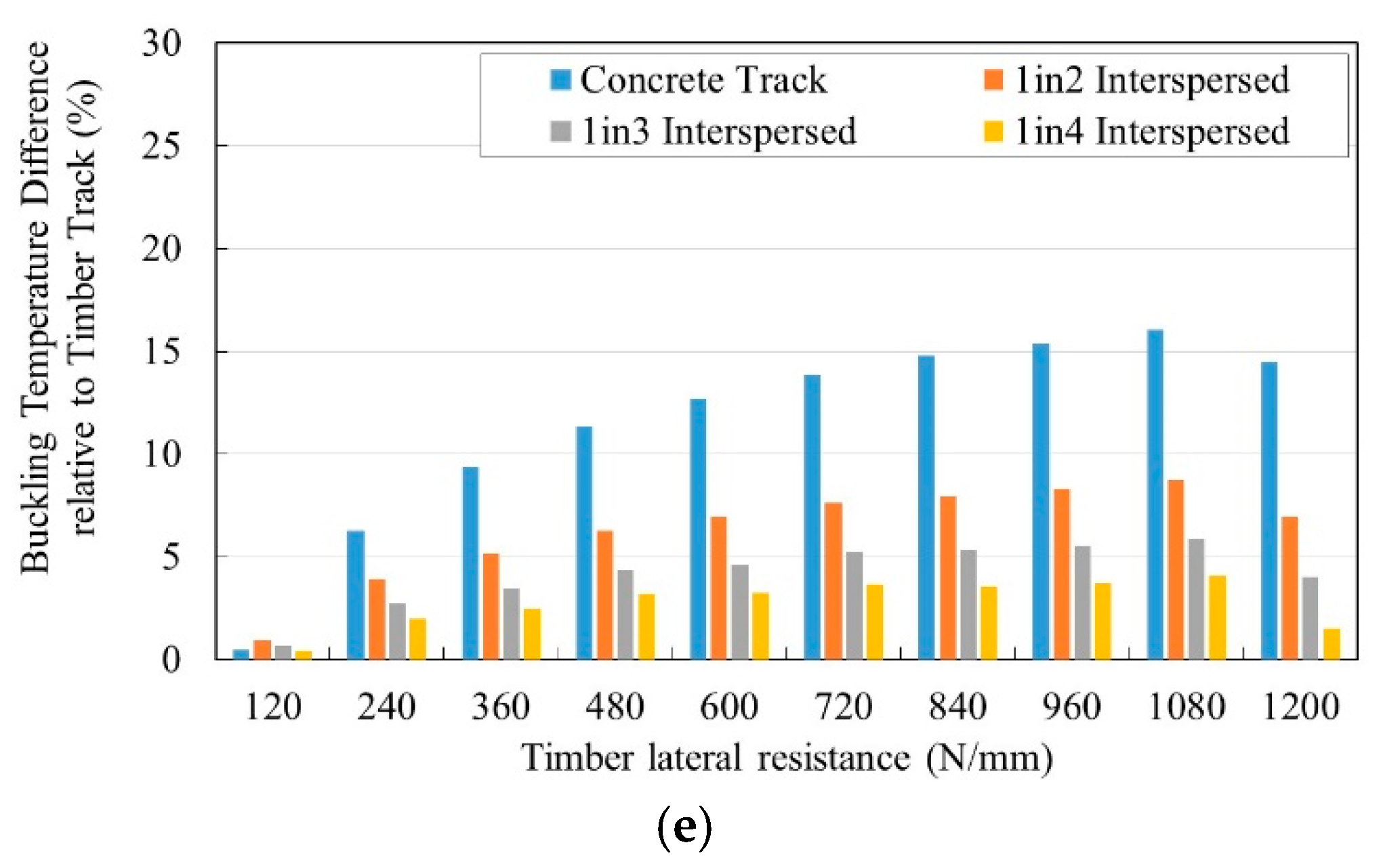
3.2. Effects of Lateral Resistance

Figure 7 presents the relationship between the buckling temperature rise above neutral temperature and timber lateral resistance at different torsional resistance levels. It should be noted that the span of timber sleepers has a lateral resistance of 60% that of concrete sleepers. It is clear that all the cases show the same trend of an increase in the buckling temperature rise above neutral when the lateral resistance is raised. Overall observations show that the increase in lateral resistance significantly improves the buckling strength, leading to an increase in the buckling temperature. The results obtained show that timber track has the worst performance in buckling prevention, while concrete track demonstrates the best buckling strength, resulting in higher buckling temperature. In terms of the interspersed railway tracks, the “1 in 2” track has better performance than “1 in 3” and “1 in 4” due to the higher number of concrete sleepers that have higher lateral resistance than timber sleepers. It is interesting to note that the more concrete sleepers on the railway track, the higher the buckling resistance. Moreover, the buckling temperature–lateral resistance relationship clearly shows a similar trend for all torsional resistance cases.

3.3. Effects of Torsional Resistance

Figure 8 illustrates the temperature change over neutral considering torsional stiffness change. It is clear that torsional stiffness also plays a role in buckling prevention. Figure 8 presents the effect of torsional stiffness and lateral stiffness values of 120 N/mm for timber sleepers and 200 N/mm for concrete sleepers. It was found that the temperature changes over neutral when employing the lowest torsional stiffness varied from 44 °C to 51 °C on all tracks. However, at the highest torsional stiffness, all tracks buckled at temperatures over 56 °C. Furthermore, when the lateral stiffness is increased, the torsional stiffness tends to have a greater effect on buckling resistance. As for the slope, it demonstrates that the torsional resistance, especially on weaker tracks such as timber and interspersed tracks, has a significant effect in increasing the buckling temperature. It is clear that the buckling strength of a concrete track cannot be notably improved by improving the torsional resistance, in comparison with interspersed and timber tracks.
Figure 9 presents the differences in temperature rise above neutral of interspersed and concrete tracks relative to timber track. Figure 9 demonstrates the replacement of timber sleepers by concrete sleepers in terms of temperature differences with consideration of lateral and torsional resistance. There are significant changes in the buckling temperature when the timber sleepers are replaced by concrete sleepers. Interestingly, concrete track can significantly improve the buckling temperature by between 10% and nearly 25% for tracks with weaker torsional resistance. Even though it seems to have less effect in replacing timber sleepers when the stronger torsional resistance is taken into account, track buckling resistance could still be improved by about 1–16%, 1–9%, 1–6% and 1–5% for concrete track and the “1 in 2”, “1 in 3”, and “1 in 4” interspersed tracks, respectively.

4. Conclusions

In this study, a 3D finite element model was developed to investigate the buckling behaviour of interspersed railway tracks. Many researchers have studied the buckling phenomena of timber sleeper tracks and concrete sleeper tracks. However, buckling analysis of interspersed tracks has never been conducted. Interestingly, interspersed railway tracks have issues of inconsistent stiffness and material properties, which are likely to increase the deterioration rate of the railway track due to uplift behaviour under a moving train. Nonetheless, interspersed tracks seem be beneficial in preventing track buckling compared with conventional timber tracks. The following key findings were revealed by the parametric studies and obtained results.
  • The “1 in 2” interspersed track possesses greater buckling strength than “1 in 3” and “1 in 4” interspersed tracks and timber tracks as more timber sleepers are substituted by concrete sleepers. Plain concrete sleeper railway track provides higher buckling strength than all other tracks.
  • The replacement of timber sleepers by concrete sleepers tends to improve buckling resistance.
  • Plain concrete track can significantly increase the buckling temperature by about 25%.
  • For weaker track lateral resistance, torsional resistance seems to significantly improve the overall resistance and increase the buckling temperature. There is no difference in buckling temperature when the torsional resistance is increased for weak track lateral resistance.
It is important to note that the current research mainly focuses on parametric studies of interspersed railway tracks. Hence, linear eigenvalue analysis is best used for preliminary study, and the effects of various parameters and geometric change were not taken into account before reaching the buckling point. It is advisable to conduct nonlinear dynamic analysis to study the behaviour of railway tracks in both the pre- and post-buckling periods to obtain the complete structural behaviour. Although interspersed tracks could increase the deterioration rate of railway tracks due to stiffness inconsistency and uplift behaviour, an improvement of buckling resistance over timber tracks can be found in interspersed tracks. However, the replacement should be done carefully since this activity probably induces ballast disturbance, leading to a loss of ballast compaction. This study is the world’s first to investigate the buckling behaviour of interspersed railway tracks, and these insights will enhance the inspection of lateral stiffness in railway systems and mitigate the risk of delays due to unplanned maintenance, thus paving a robust pathway for a practical impact on society.

Author Contributions

Conceptualisation, C.N. and S.K.; methodology, C.N.; software, C.N. and C.M.W.; validation, C.N., and C.M.W.; formal analysis, C.W.; investigation, C.N., C.M.W. and S.K.; resources, S.K.; writing—original draft preparation, C.M.W.; writing—review and editing, C.N. and S.K.; visualisation, C.N.; supervision, S.K.; project administration, S.K.; funding acquisition, S.K. All authors have read and agreed to the published version of the manuscript.

Funding

This research was funded by European Commission, grant numbers: H2020-MSCA-RISE No. 691135.

Acknowledgments

The authors are sincerely grateful to European Commission for the financial sponsorship of the H2020-MSCA-RISE Project No. 691135 “RISEN: Rail Infrastructure Systems Engineering Network,” which enables a global research network that tackles the grand challenge of railway infrastructure resilience and advanced sensing in extreme environments (www.risen2rail.eu) [57].

Conflicts of Interest

The authors declare no conflict of interest.

References

  1. Hamzah, S.H.; Din, K. Appraisal of used wooden railway sleeper. J. Eng. Sci. Technol. 2018, 3, 224–233. [Google Scholar]
  2. Kaewunruen, S.; Remennikov, A.M.; Aikawa, A.; Hirotaka, S. Free vibrations of interspersed railway track systems in three-dimensional space. Acoust. Aust 2014, 42, 20–26. [Google Scholar]
  3. Kohoutek, R.; Campbell, K.D. Analysis of Spot Replacement Sleepers. In Proceedings of the Fourth International Heavy Haul Railway Conference 1989, Brisbane, Australia, 11–15 September 1989. [Google Scholar]
  4. Ferdous, W.; Manalo, A.; Van Erp, G.; Aravinthan, T.; Kaewunruen, S.; Remennikov, A.M. Composite railway sleepers – Recent developments, challenges and future prospects. Compos. Struct. 2015, 134, 158–168. [Google Scholar] [CrossRef]
  5. Gustavson, R. Structural Behaviour of Concrete Railway Sleepers. Ph.D. Thesis, Department of Structural Engineering, Chalmers University of Technology, Gothenburg, Sweden, 2002. [Google Scholar]
  6. Kaewunruen, S.; Chamniprasart, K. Damage analysis of spot replacement sleepers interspersed in ballasted railway tracks. In Proceedings of the 29th Nordic Seminar on Computational Mechanics, Chalmers University of Technology, Gothenburg, Sweden, 24–25 October 2016. [Google Scholar]
  7. Kohoutek, R. Dynamic and static performance of interspersed railway track. In Proceedings of the Railway Engineering, Adelaide, Australia, 23–25 September 1991. [Google Scholar]
  8. Lake, M.; Ferreira, L.; Murray, M.H. Using simulation to evaluate rail sleeper replacement alternatives. Transport. Res. Rec. 2002, 1785, 58–63. [Google Scholar] [CrossRef] [Green Version]
  9. Kaewunruen, S.; Minoura, S.; Watanabe, T.; Remennikov, A.M. Remaining service life of railway prestressed concrete sleepers. In RILEM Conf. Materials, Systems and Structures in Civil Engineering; DTU: Lyngby, Denmark, 2016. [Google Scholar]
  10. Connolly, D.P.; Kouroussis, G.; Laghrouche, O.; Ho, C.L.; Forde, M.C. Benchmarking railway vibrations—Track, vehicle, ground and building effects. Constr. Build. Mater. 2015, 92, 64–81. [Google Scholar] [CrossRef] [Green Version]
  11. Kaewunruen, S.; Remennikov, A.M. Experimental simulation of the railway ballast by resilient materials and its verification by modal testing. Exp. Tech. 2008, 32, 29–35. [Google Scholar] [CrossRef]
  12. Kaewunruen, S.; Remennikov, A.M. Nonlinear transient analysis of a railway concrete sleeper in a track system. Int. J. Struct. Stab. Dyn. 2008, 8, 505–520. [Google Scholar] [CrossRef]
  13. Kaewunruen, S.; Ngamkhanong, C.; Janeliukstis, R.; You, R. Influences of surface abrasion on dynamic behaviours of railway concrete sleepers. In Proceedings of the 24th International Congress on Sound and Vibration, London, UK, 20–24 July 2017. [Google Scholar]
  14. Kaewunruen, S.; Remennikov, A.M. Impact capacity of railway prestressed concrete sleepers. Eng. Fail. Anal. 2009, 16, 1520–1532. [Google Scholar] [CrossRef]
  15. Ngamkhanong, C.; Li, D.; Kaewunruen, S. Impact capacity reduction in railway prestressed concrete sleepers with surface abrasions. IOP Conf. Ser. Mater. Sci. Eng. 2007, 245. [Google Scholar] [CrossRef]
  16. Ngamkhanong, C.; Kaewunruen, S.; Baniotopoulos, C. A review on modelling and monitoring of railway ballast. Struct. Monit. Maint. 2017, 4, 195–220. [Google Scholar]
  17. Ngamkhanong, C.; Li, D.; Remennikov, A.M.; Kaewunruen, S. Dynamic capacity reduction of railway prestressed concrete sleepers due to surface abrasions considering the effects of strain rate and prestressing losses. Int. J. Struct. Stab. Dyn. 2018, 19, 1940001. [Google Scholar] [CrossRef]
  18. Kaewunruen, S.; Lewandrowski, T.; Chamniprasart, K. Nonlinear modelling and analysis of moving train loads on interspersed railway tracks. In Proceedings of the 6th ECCOMAS Thematic Conference on Computational Methods in Structural Dynamics and Earthquake Engineering, Rhodes Island, Greece, 15–17 June 2018. [Google Scholar]
  19. Kaewunruen, S.; Lewandrowski, T.; Chamniprasart, K. Dynamic Responses of Interspersed Railway Tracks to Moving Train Loads. Int. J. Struct. Stab. Dyn. 2018, 18. [Google Scholar] [CrossRef]
  20. Kaewunruen, S.; Ng, J.; Aikawa, A. Sensitivity of Rail Pads on Dynamic Responses of Spot Replacement Sleepers Interspersed in Ballasted Railway Tracks. In Proceedings of the 25th International Congress on Sound and Vibration, Hiroshima, Japan, 8–12 July 2018. [Google Scholar]
  21. Kaewunruen, S.; Ngamkhanong, C.; Ng, J. Influence of time-dependent material degradation on life cycle serviceability of interspersed railway tracks due to moving train loads. Eng. Struct. 2019, 199, 109625. [Google Scholar] [CrossRef]
  22. Stipanovic, I.; Maat, H.T.; Hartmann, A.; Dewulf, G. Risk Assessment of Climate Change Impacts on Railway. In Proceedings of the Engineering Project Organization Conference EPOC 2013, Tabernash, CO, USA, 9–11 July 2013. [Google Scholar]
  23. Quinn, A.D.; Jack, A.; Hodgkinson, S.; Ferranti, E.J.S.; Beckford, J.; Dora, J. RAIL ADAPT Adapting the Railway for the Future; International Union of Railways (UIC): Paris, France, 2017. [Google Scholar]
  24. Ngamkhanong, C.; Kaewunruen, S.; Costa, B.J.A. State-of-the-Art Review of Railway Track Resilience Monitoring. Infrastructures 2018, 3, 3. [Google Scholar] [CrossRef] [Green Version]
  25. Ahmad, S.S.N.; Mandal, N.K.; Chattopadhyay, G. A Comparative Study of Track Buckling Parameters of Continuous Welded Rail. In Proceedings of the International Conference on Mechanical Engineering 2009 (ICME2009), Dhaka, Bangladesh, 26–28 December 2009. [Google Scholar]
  26. Esveld, C. Modern Railway Track, 2nd ed.; MRT-Productions: Delft, The Netherlands, 2001. [Google Scholar]
  27. Kish, A.; Samavedam, G. Track Buckling Prevention: Theory, Safety Concepts, and Applications; Report No. DOT/FRA/ORD-13/16; Department of Transportation, Federal RailroadAdministration, Office of Research and Development: Washington, DC, USA, 2013. [Google Scholar]
  28. Esveld, C. Improved Knowledge of CWR Track; Delft University of Technology: Delft, The Netherlands, 1997. [Google Scholar]
  29. Thompson, W.C. Union Pacific’s Approach to Preserving Lateral Track Stability. Transp. Res. Rec. 1991, 1289, 64–70. [Google Scholar]
  30. Ling, L.; Xiao, X.B.; Cao, Y.B.; Wu, L.; Wen, Z.; Jin, X.S. Numerical simulation of dynamical derailment of high-speed train using a 3D train–track model. In Proceedings of the Second International Conference on Railway Technology: Research, Development and Maintenance, Corsica, France, 8–11 April 2014. [Google Scholar]
  31. Ling, L.; Xiao, X.B.; Jin, X.S. Development of a simulation model for dynamic derailment analysis of high-speed trains. Acta Mech. Sin. 2014, 30, 860–875. [Google Scholar] [CrossRef]
  32. Kaewunruen, S.; Wang, Y.; Ngamkhanong, C. Derailment-resistant performance of modular composite rail track slabs. Eng. Struct. 2018, 160, 1–11. [Google Scholar]
  33. Strauss, A.; Šomodíková, M.; Lehký, D.; Novák, D.; Bergmeister, K. Nonlinear finite element analysis of continuous welded rail–bridge interaction: monitoring-based calibration. J. Civ. Eng. Manag. 2018, 24, 344–354. [Google Scholar] [CrossRef]
  34. Kang, C.; Bode, M.; Wenner, M.; Marx, S. Experimental and numerical investigations of rail behaviour under compressive force on ballastless track systems. Eng. Struct. 2019, 197, 109413. [Google Scholar] [CrossRef]
  35. Strauss, A.; Karimi, S.; Šomodíková, M.; Lehký, D.; Novák, D.; Frangopol, D.M.; Bergmeister, K. Monitoring based nonlinear system modeling of bridge–continuous welded rail interaction. Eng. Struct. 2018, 155, 25–35. [Google Scholar] [CrossRef]
  36. Prud’homme, M.A.; Janin, G. The stability of tracks laid with long welded rails. Int. Rail. Cong. Ass. 1969, 46, 459–487. [Google Scholar]
  37. Kerr, A.D. Analysis of thermal track buckling in lateral plane. Acta Mech. 1978, 30, 17–50. [Google Scholar] [CrossRef] [Green Version]
  38. Kerr, A.D. An improved analysis for thermal track buckling. Int. J. Nonlinear Mech. 1980, 15, 99–114. [Google Scholar] [CrossRef]
  39. Samavedam, G.; Kish, A.; Purple, A.; Schoengart, J. Parametric Analysis and Safety Concepts of CWR Track Buckling; DOT/FRA/ORD-93/26; Federal Railroad Administration: Washington, DC, USA, 1993. [Google Scholar]
  40. Sussmann, T.; Kish, A.; Trosino, M. Investigation of the Influence of Track Maintenance on the Lateral Resistance of Concrete Tie Track. In Proceedings of the Annual Meeting of the Transportation Research Board, Washington, DC, USA, 12–16 January 2003. [Google Scholar]
  41. CRC for Rail Innovation, Track Stability Management—Literature Review; Theories and Practices: Brisbane, Australia, 2009.
  42. Ole, Z.K. Track Stability and Buckling—Rail Stress Management. Bachelor’s Thesis, University of Southern Queensland, Toowoomba, Australia, 2008. [Google Scholar]
  43. Carvalho, J.; Delgado, J.; Calçada, C.; Delgado, R. A new methodology for evaluating the safe temperature in continuous welded rail tracks. Int. J. Struct. Stab. Dyn. 2013, 13, 1350016. [Google Scholar] [CrossRef]
  44. Kish, A. On the Fundamentals of Track Lateral Resistance. In Proceedings of the Annual Conference 2011, Minneapolis, MN, USA, 18–21 September 2011. [Google Scholar]
  45. Zakeri, J.A.; Esmaeili, M.; Kasraei, A.; Bakhtiary, A. A numerical investigation on the lateral resistance of frictional sleepers in ballasted railway tracks. Proc. Imeche Part F J. Rail Rapid Transit 2014, 230, 440–449. [Google Scholar] [CrossRef]
  46. Zakeri, J.A.; Mirfattahi, B.; Fakhari, M. Lateral resistance of railway track with frictional sleepers. Proc. Inst. Civ. Eng. Transp. 2012, 165, 151–155. [Google Scholar]
  47. Zakeri, J.A.; Bakhtiary, A. Comparing lateral resistance to different types of sleeper in ballasted railway tracks. Sci. Iran. A 2014, 21, 101–107. [Google Scholar]
  48. Kish, A.; Clark, D.W.; Thompson, W. Recent Investigations on the Lateral Stability of Wood and Concrete Tie Tracks. Area Bull. 1995, 752, 248–265. [Google Scholar]
  49. Lichtberger, B. The lateral resistance of the track. Eur. Railw. Rev. 2007, 68–71. [Google Scholar]
  50. Tutumluer, E.; Huang, H.; Hashash, Y.; Ghaboussi, J. Aggregate shape effects on ballast tamping and railroad track lateral stability. In Proceedings of the AREMA 2006 Annual Conference, Louisville, KY, USA, 17–20 September 2006. [Google Scholar]
  51. G+D Computing. Using Strand7: Introduction to the Strand7 Finite Element Analysis System; G+D Computing: Sydney, Australia, 2001. [Google Scholar]
  52. Kaewunruen, S.; Freimanis, A.; Goto, K. Impact Responses of Railway Concrete Sleepers with Surface Abrasions. In Proceedings of the 25th International Congress on Sound and Vibration, Hiroshima, Japan, 8–12 July 2018. [Google Scholar]
  53. Cai, Z. Modelling of Rail Track Dynamics and Wheel/Rail Interaction. Ph.D. Thesis, Department of Civil Engineering, Queen’s University, Kingston, ON, Canada, 1992. [Google Scholar]
  54. Remennikov, A.M.; Kaewunruen, S. Determination of dynamic properties of rail pads using an instrumented hammer impact technique. Acoust. Aust. 2005, 33, 63–67. [Google Scholar]
  55. Ghazaly, H.A.; Herbourne, A.N.; Arbabi, F. Strength and stability of railway tracks—II. Deterministic, finite-element stability analysis. Comput. Struct. 1991, 39, 23–45. [Google Scholar] [CrossRef]
  56. Yang, G.; Bradford, M.A. Thermal-induced buckling and postbuckling analysis of continuous railway tracks. Int. J. Solids Struct. 2016, 97–98, 637–649. [Google Scholar] [CrossRef]
  57. Kaewunruen, S.; Sussman, J.M.; Matsumoto, A. Grand Challenges in Transportation and Transit Systems. Front. Built Environ. 2016, 2, 4. [Google Scholar] [CrossRef] [Green Version]
Figure 1. An interspersed railway track [6,18,19,20,21].
Applsci 10 03091 g001
Figure 2. Railway track models: (a) concrete track; (b) timber track; (c) “1 in 2” interspersed track; (d) “1 in 3” interspersed track; (e) “1 in 4” interspersed track.
Applsci 10 03091 g002aApplsci 10 03091 g002b
Figure 3. Typical buckling shape of the railway track and support constraints: (a) symmetrical and (b) antisymmetrical buckling shapes.
Applsci 10 03091 g003
Figure 4. Buckling path.
Applsci 10 03091 g004
Figure 5. Linear bifurcation buckling path.
Applsci 10 03091 g005
Figure 6. Buckling shapes and normalized displacements of railway tracks with different lateral resistances.
Applsci 10 03091 g006
Figure 7. Temperature rise above neutral: (a) Nominal torsional resistance value; (b) 50% reduction of nominal torsional resistance value; (c) 25% reduction of nominal torsional resistance value; (d) 25% increase of nominal torsional resistance value; (e) 50% increase of nominal torsional resistance value.
Applsci 10 03091 g007aApplsci 10 03091 g007b
Figure 8. Temperature rise above neutral: (a) Lateral stiffness = 120 N/mm (Timber), 200 N/mm (Concrete); (b) Lateral stiffness = 360 N/mm (Timber), 600 N/mm (Concrete); (c) Lateral stiffness = 600 N/mm (Timber), 1000 N/mm (Concrete); (d) Lateral stiffness = 840 N/mm (Timber), 1400 N/mm (Concrete); (e) Lateral stiffness = 1200 N/mm (Timber), 2000 N/mm (Concrete).
Applsci 10 03091 g008aApplsci 10 03091 g008b
Figure 9. Buckling temperature difference relative to timber track: (a) Nominal torsional resistance value; (b) 50% reduction of nominal torsional resistance value; (c) 25% reduction of nominal torsional resistance value; (d) 25% increase of nominal torsional resistance value; (e) 50% increase of nominal torsional resistance value.
Applsci 10 03091 g009aApplsci 10 03091 g009b
Table 1. Material properties.
ParameterCharacteristic ValueUnit
Rail (UIC60)
Gauge, g1.435m
Modulus, Er2e5MPa
Poisson’s ratio, vr0.25-
Density, dr7850kg/m3
Thermal expansion1.17e-51/°C
Concrete sleeper
Modulus, Es3.75e4MPa
Shear modulus, Gs1.09e4MPa
Density, dr2740kg/m3
Lateral resistance200–2000N/mm
Torsional resistance28.5–84.7 (Nominal value = 56.4)kNm/rad
Timber sleeper
Modulus, Es1.02e4MPa
Shear modulus, Gs3.93e3MPa
Density, dr1100kg/m3
Lateral resistance120–1200N/mm
Torsional resistance71.2–211.8 (Nominal value = 141.0)kNm/rad
Table 2. Buckling temperatures for model validation.
CaseAnalytical Solutions (°C)Previous FEM (°C) [43]Average (°C)This Study (°C)Difference (%)
Prud’homme and Janin [36]Kerr [38]
Torsional resistance = 75 kNm/rad57.747.850.051.83532.23
Table 3. Buckling shapes.
Lateral Resistance (N/mm)Timber (“1 in 1” Interspersed Track)“1 in 2” Interspersed Track“1 in 3” Interspersed Track“1 in 4” Interspersed TrackConcrete Track
Timber: 120 Applsci 10 03091 i001 Applsci 10 03091 i002 Applsci 10 03091 i003 Applsci 10 03091 i004 Applsci 10 03091 i005
Concrete: 200
Timber: 360 Applsci 10 03091 i006 Applsci 10 03091 i007 Applsci 10 03091 i008 Applsci 10 03091 i009 Applsci 10 03091 i010
Concrete: 600
Timber: 600 Applsci 10 03091 i011 Applsci 10 03091 i012 Applsci 10 03091 i013 Applsci 10 03091 i014 Applsci 10 03091 i015
Concrete: 1000
Timber: 840 Applsci 10 03091 i016 Applsci 10 03091 i017 Applsci 10 03091 i018 Applsci 10 03091 i019 Applsci 10 03091 i020
Concrete: 1400
Timber: 1200 Applsci 10 03091 i021 Applsci 10 03091 i022 Applsci 10 03091 i023 Applsci 10 03091 i024 Applsci 10 03091 i025
Concrete: 2000

