1. Introduction
There has been an increased interest in reducing macro to micro systems and then to nano systems over the recent years. Therefore, the mechanical devices which use classical mechanisms are heading to a new level of development—the compliant mechanisms. No matter what kind of devices you see every day, they have some underlying mechanisms that govern the motion that produces the desired output. Mechanisms are used to transform and transfer motion, force, or energy. Traditional rigid body mechanisms consist of rigid links interconnected by joints [
1]. In response to the specific requirements imposed by the miniaturization process, new types of mechanisms, inspired by nature, have been developed, which are compliant mechanisms [
2,
3,
4].
Compliant mechanisms have been used for decades in different fields and industries. Unlike rigid-link mechanisms and movable joints, the compliant mechanisms gain at least some of their mobility from the deflection of the flexible members.
There are very stable and reliable mechanical structures with flexible hinges and rigid or flexible elements that can be considered fully or partially compliant mechanisms [
1]. There has been a huge interest in the topic of compliant mechanisms worldwide and some of the main representative works are the ones that will be presented hereinafter.
First, we mention the patents [
5,
6] where universal clamping devices are proposed. This device has a movable arm. We consider this invention as representative for our field of interest since it is the classic version, where there is the possibility to change arms. This movable arm is locked in a gripping position by gripping against a movable locking element. A pair of swivel arms are held in the grip positions by a linear sliding locking element between the ends of the arms. The variable configurations of the movable arms can be easily changed between them and it can be mounted on a body by means of a single fixed pivot. The opening angle of a clamping arm can be mechanically limited to different positions by the selective positioning of an adjusting element. There is also the work of Tanikawa et al. [
7] who developed a dexterous micro-manipulation system for applications such as micro machine assembly, cell manipulation and microsurgery. He proposed a concept of a two-fingered micro-hand and designed and built a prototype. Basic micro-manipulations were performed, including grasping, releasing and rotating a microscopic object [
7].
In [
8], a new design of the mobile micro-manipulation system for the robotic micro assembly is presented. This is a design where a piezoelectric actuator-based clamping device is developed for handling miniature parts with a compensation of the misalignment during the peg-in-hole assembly is done because the piezoelectric actuator can produce micron shift and generate high force instantly [
8]. Inventor Tatsuo Arai [
9] creates a micromanipulator that comprises a pair of hand modules each. They include a circular base plate with three connection points, a final effector consisting of a moving circular plate and a finger attached to the mobile plate. The solution of the invention relates to a micromanipulator adapted for the use that requires precise positioning in the μm range, in particular for use in the integrated circuit (IC) industry (for precise chip positioning), in bioengineering, medicine (microsurgery), satellite communications (precise positioning antenna), etc. [
10]. Gendreau, D., Rakotondrabe M., and Lutz, P. [
11] have developed a new method for designing micro-business systems. This method based on modularity combines a top-down approach related to production systems with a bottom-up approach to consider the specific constraints of microworld technologies and know-how. In order to perform an assembly task, we need operating devices and scenarios adapted to the manipulation. The station was composed of two micro-robots that work in cooperation to perform pick-and-place sequences of the pieces measuring between 200 and 500 μm. The performance criterion is focused on the success of the operation in automatic mode [
11]. Lobontiu et al. [
12] proposed a new model for flexure hinge with the aim to increase the force or the displacement which can be transmitted towards the end-effector, using different shapes of the flexure hinges. Ivan A. et al. [
13] discussed about bending piezo actuators which give a large displacement in the mini and micro systems functioning.
We have chosen to present several directions in which scientists and researchers have made an important discovery for the development of the compliant mechanisms over the last decade.
A modular manipulation cell concept, with positioning systems and compliant microgrippers with different types of jaws is proposed in this paper. The SiMFlex micromanipulation cell can be reconfigured according to the overall dimensions for the micro grasping object.
2. SiMFlex Cell Concept
The SiMFlex micromanipulation cell is a modular construction concept, with the possibility of being reconfigured for different specific applications in micro assembly or grasping the small objects. The SiMFlex cell can work as an independent unit or with different auxiliary systems attached to it such as: sensors, additionally control system, cleaning system, etc. The compact size is a big advantage, so it can be very easily integrated in different places for manufacturing or micromanipulation purposes. The designed system (
Figure 1) has three main modules: the base platform for working area, the micro positioning system, and the micromanipulation system. Each module has different design variants which can be combined for specific applications.
The base platform that has the overall dimensions of 136 × 136 mm. and the possibility of vibration isolation in for the working area is presented in
Figure 1.
The micromanipulation system has three parts: compliant gripper with a piezoelectric stack actuator and jaws. This module will be discussed in the next chapter.
The positioning system has translation stages for each axis: Ox, Oy, and Oz. The parts can be coupled in several ways in order to increase the precision along one specific axis. One example is presented in
Figure 1a where the maximum displacements along Oz and Ox are 12 mm. Along the y axis, the maximum stroke value is 5 mm and a precise positioning with differential adjuster is realized.
In
Figure 1b, another variant is presented where the precise positioning part for displacement stroke is positioned along Oy axis. For the whole positioning system, with all three parts, the active workspace is 12 × 12 × 5 mm [
14].
3. Manipulation Module
In
Figure 2, the micro manipulating module is presented. It has a basic compliant gripper part (1) and a piezoelectric stack actuator (2). The jaws (3) can be attached in two different ways: one with interchangeable jaws (3a) and the other with bending piezoelectric jaws (3b). For interchangeable jaws, three variants are proposed: circular, rectangular, and general shapes. The bending piezoelectric jaws can be closed at the same time or only one at a time.
The basic compliant gripper part (1) possesses a symmetry line along the piezoelectric actuator and it has 12 identically flexible joints with a corner filleted shape (
Figure 2b), defined by the length of the flexure hinge (l
f), the thickness (t), and radius (r). When the radius r increases, a less stress concentration and displacement results at the flexure hinge, but it increases the transmitted force [
2].
The movement of the flexure hinge in the mechanism with various cross-section used in the gripper structure can be analyzed with the generic equations of Castigliano theorem.
where: M
i—bending moment, I—inertia moment, E—Young’s modulus of the flexure hinge.
The displacement of flexure hinge is directly proportional to the length of the flexure hinge (lf). As length increases the stiffness decreases and a displacement increase occurs at the same time. The analysis also can indicate that the overall thickness (b) and the flexure hinge thickness (t) determine the bending stiffness of the flexure hinge. The increase of these parameters increases the bending stiffness and hence reduces the output displacement.
The mechanical advantage for main compliant gripper can be found as the ratio of the input displacement from stack piezoelectric actuator,
, to the output displacement from jaws,
(
Figure 3). The input displacement is determined by applying only the force Pi at the input port by using, again, Castigliano’s theorem in the form:
The displacement at the output port under the action of Pi can be calculated by using a dummy force Po through:
The methodology for relations between displacement and force applied to the micro-objects was detailed by authors in [
2,
15].
By combining Equations (2) and (3), the mechanical advantage is obtained in the form:
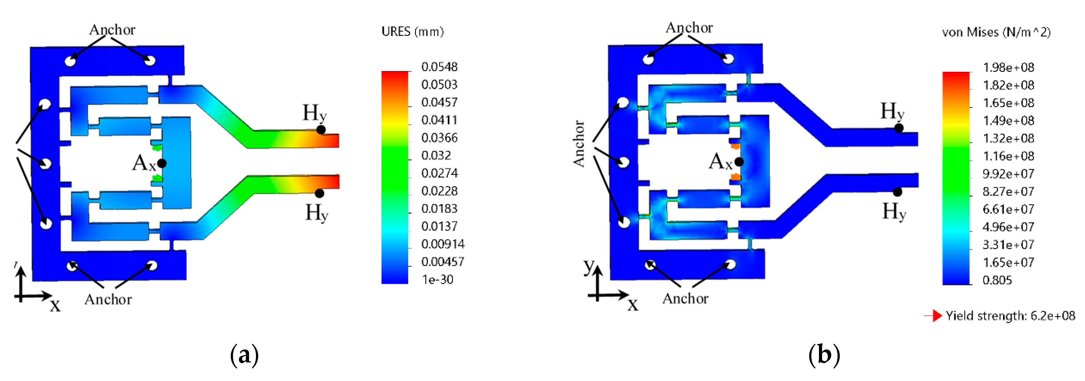
The Finite Element Method (FEM) analysis for compliant gripper was realized, using Solidworks Simulation, considering a maximum displacement of 10 μm for the piezoelectric stack actuator. The basic compliant gripper part has overall dimensions of 54 × 41 × 3.80 mm, also, the flexure hinges have the dimensions: lf = 2 mm, t = 0.56 mm, and r = 0.3 mm.
The mechanism out-of-plane thickness was w = 3.80 mm. The material used was steel alloy with an elastic modulus E = 2.1 · 1011 N/m2, and Poisson’s ratio μ = 0.28.
The simulation considered the output point is free, condition for which the displacements (
Figure 3a), and the Von Mises stress (
Figure 3b) have been evaluated by means of the resulting input and output displacements. For the FEM analysis was used a standard solid mesh type with four Jacobian points, which generated the 21,018 nodes and 11,686 elements.
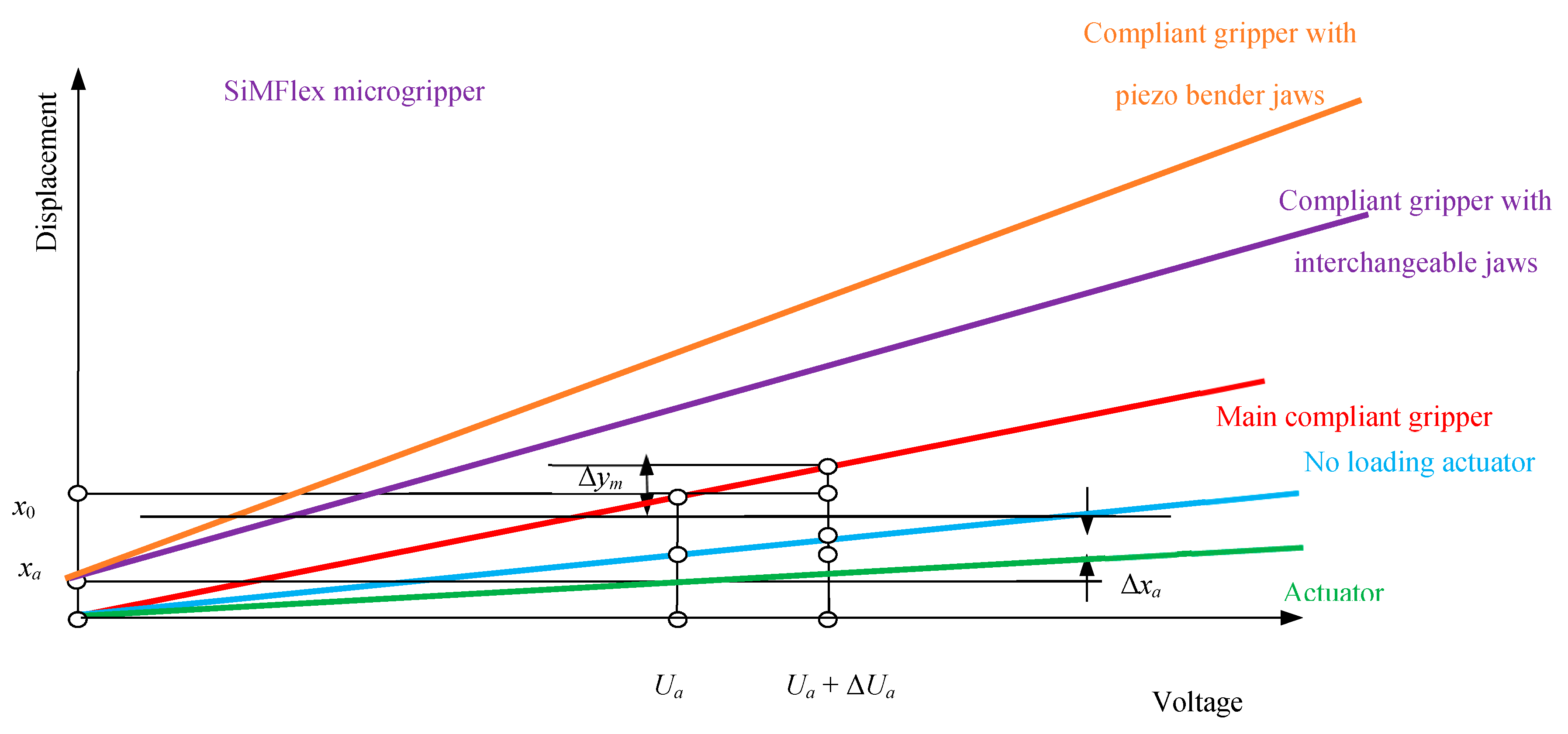
When the jaws are attached, the displacement values increase with a ratio which depends on the length of the interchangeable jaws. When attached the piezoelectric bending the workspace and number of the manipulated objects increase because it is necessary to add ±450 μm from the displacements which results when it is applied a maximum voltages value of 150 V at actuators.
The displacements diagram for different variants can be seen in
Figure 4.
The overall dimensions of the SiMFlex cell are 136 × 136 × 102 mm which is quite compact.
4. SiMFlex Prototype and Testing
A prototype for SiMFlex cell was designed with three linear translation stages (
Figure 5). The linear movement along y axis is provided by the translational module which is a linear flexure stage with differential micrometer and a piezo drive with strain gauge feedback. The overall dimensions of the module are: 139 × 75 × 29.5 mm. A maximum displacement of 5 mm is ensured by differential micrometers which also provide fine and coarse adjustments. The fine adjuster travel is 300 µm with an accuracy of 1 µm. At any position ensured by the differential micrometer, a maximum displacement of 20 µm provided by the piezo drive can be added. In this case, the strain gauge feedback offers a theoretical resolution of 0.6 nm. The translational movements along the × and z axis are ensured by another two-axis miniature dovetail stage with M3 × 30 mm lead screws [
14]. The overall dimensions for this module are: 58 × 43 × 72.4 mm and the maximum displacements ensured are 12.7 mm on each axis.
The micromanipulation system had only the main compliant gripper and the piezoelectric bender with ±450 μm displacement or interchangeable jaws can be attached to it. The input from the main compliant gripper came from the piezoelectric stack actuator with 6.5 × 6.5 × 18 mm overall dimensions and the maximum 15 μm stroke along the × axis, when 100-V tension was applied. Also, the technical description has a hysteresis ±12% from stroke [
15].
The experimental study was focused on the displacement response of the piezo actuato by usingsinusoidal signals.
Figure 5b shows the picture of the testing bench with laser sensors. The first measured test was for the input signal by main compliant gripper which came from stack piezoelectric actuator. In the case of the stack piezoelectric actuator, there is a sinusoidal signal with a value of 20 V that has a result of a 4 µm displacement stroke. Also, there was also applied 100 V, which resulted in a 13 µm displacement stroke (
Figure 6a). The for voltage/displacement charts are presented in
Figure 6b.
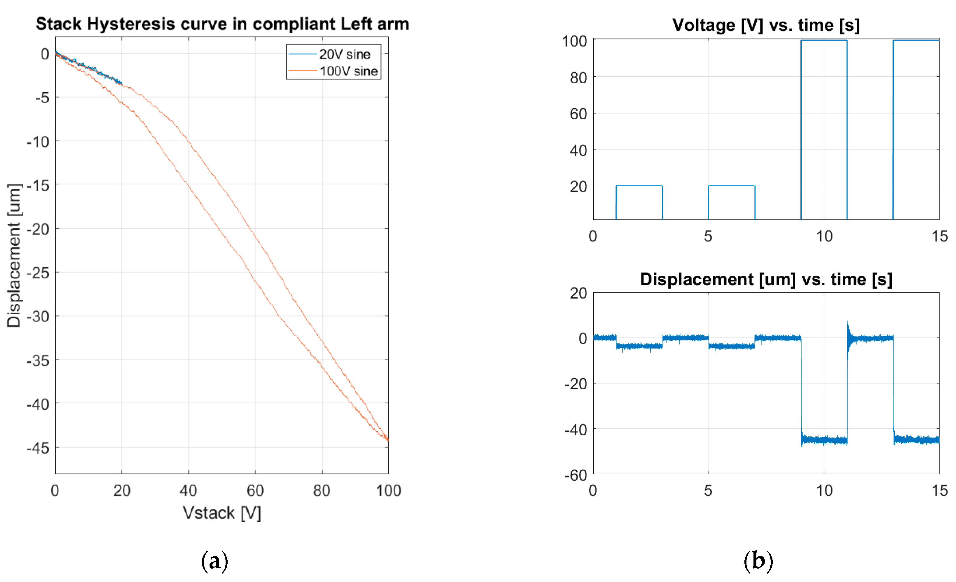
The second measured test was for the output signals at the compliant gripper jaws level. The measurement was realized for the left and the right arm separately. For the left arm, when at stack piezoelectric actuator, a sinusoidal signal with of 100 V amplitude was applied and a 45 µm displacement stroke resulted (
Figure 7a). Also, the values for voltage/displacement versus time are presented in
Figure 7b.
Similar test was performed for the output signal of the right arm of the compliant gripper. A sine wave of 100 V amplitude was applied and 44.8 µm displacement stroke resulted (
Figure 8a). The values for voltage/displacement versus time are presented in
Figure 8b.
The final measurement test was at the bender jaws, which are the end-points of the compliant gripper mounted as in
Figure 2. Thede bending actuators were tested separately, the piezostack being kept at 0 V. When a sinusoidal signal with value ±75 V was applied on the piezoelectric bender and 375 µm displacement strokes resulted (
Figure 9a). The voltage/displacement values versus time are presented in
Figure 9b.
Additional experimental testing with micro objects manipulated with the different shapes of jaws are performed according to the methodology developed by the authors of [
16,
17,
18].
After the comparison of the values between FEM analysis and experimental results, the differences were about 10% and the SiMFlex micromanipulation cell was validated.
An application for the SiMFlex cell was built with the overall dimension of 136 × 136 × 102 mm.
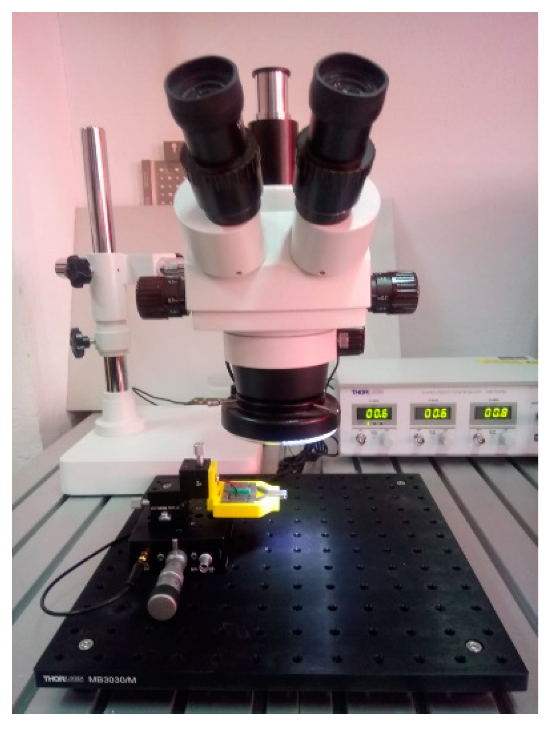
All of the small movements and the grasping process is difficult to observe, so for the micromanipulation applications, the proposed SiMFlex cell can be used in conjunction with a stereo industrial microscope, as presented in
Figure 10. The industrial microscope used is a trinocular 7X–45Xzoom stereo microscope head with photo/video capability equipped with 10×/20 mm eyepieces. One of the eyepieces has a micrometric scale.
For micromanipulation, the overall position of the griper is set using the adjustment screws. The precision movement along one axis is ensured using the linear flexure stage with piezo drive. For piezo actuators we use an MDT693B - 3-Channel, Open-Loop Piezo Controller from Thorlabs. One channel set at 75 V, is used to drive the linear flexure stage in open loop mode, and another channel set to 100 V is used to actuate the compliant gripper with stack piezoactuator.
One future objective is to implement a more flexible configuration in order to accommodate various dimensions for the micromanipulated objects. Also, the SiMFlex closed-loop position control can be achieved using the flexure stage’s embedded strain gauge sensors. Besides the existing equipment, this involves a Proportional-Integral (PI) controller and an instrumentation amplifier for reading the signal from the strain gauge sensors. In this configuration, the hysteresis error can be compensated, and the positioning accuracy will be increased. In addition, grasping and manipulation operations can be fully automated.
5. Conclusions
A modular structure for a micromanipulation cell was proposed in this paper. The modular structure facilitates the layout configuration of for micromanipulation, such as pick-and-place operation as well as microassembly for product manufacturing. The SiMFlex micromanipulation cell with modular structure was designed with two types of stack and bending piezo actuators and also has three main modules: base platform for working area, micro positioning system, and micro manipulation system. The module for achieving large workspace is the one equipped with the piezo bending actuators, the piezostack being intended for precision manipulation as well as for range extension if the application requires.
The FEM analysis model predictions were confirmed by the experimental data of the gripper prototype. The SiMFlex can be successfully applied to the fields that need high precision in small workspaces, such as: optics, precision machine tools, and mini component fabrication. For a specific application case, it is essential to establish the overall dimension for a manipulated micro object and for the operations that will be done.
Author Contributions
Conceptualization, S.N., D.C.N., C.R., and D.L.; methodology, S.N. and D.C.N.; software, S.N.; validation, I.A.I. and S.N.; formal analysis, S.N.; investigation, I.A.I.; resources, C.R.; data curation, I.A.I.; writing—original draft preparation, S.N., D.C.N., C.R., and D.L.; writing—review and editing, S.N., D.C.N., I.A.I., and C.R.; visualization, D.C.N. and I.A.I.; supervision, D.C.N.; project administration, S.N.; funding acquisition, C.R. All authors have read and agreed to the published version of the manuscript.
Funding
This research was funded by TECHNICAL UNIVERSITY OF CLUJ-NAPOCA in the framework of the GNaC 2018 ARUT “Sistem de Micromanipulare cu Actuatori Piezoelectrici si Flexibilitate Funcţională – SiMFlex”, grant number 168/2019.
Conflicts of Interest
The authors declare no conflict of interest.
References
- Lates, D.; Casvean, M. Compliant Mechanisms in Progress and Development of Modern Technology. Int. J. Eng. Manag. Sci. (Debr.) 2019, 5, 73–74. [Google Scholar]
- Noveanu, S. Contributions Concerning the Study of Compliant Mechanisms Specific to Mechatronic Systems. Ph.D. Thesis, Technical University of Cluj-Napoca, Cluj-Napoca, Romania, 2009. [Google Scholar]
- Lobonţiu, N. Compliant Mechanisms: Design of Flexure Hinges, 1st ed.; CRC Press LLC: New York, NY, USA, 2002. [Google Scholar]
- Smith, S.T. Flexures: Elements of Elastic Mechanisms, 1st ed.; CRC Press LLC: New York, NY, USA, 2000. [Google Scholar]
- Edwin, G.S.; Dean, J.K.; Steven, J.S. Universal Gripper. U.S. Patent 5,853,211, 29 December 1998. [Google Scholar]
- Nabil, M.R.; Mark, D.L. Quick-Change Finger for Robotic Gripper. U.S. Patent 8,382,177, 26 February 2013. [Google Scholar]
- Tanikawa, T.; Arai, T.; Koyachi, N. Development of small-sized 3 DOF finger module in micro hand for micro manipulation. In Proceedings of the IEEE/RSJ International Conference on Intelligent Robots and Systems. Human and Environment Friendly Robots with High Intelligence and Emotional Quotients (Cat. No.99CH36289), Kyongju, Korea, 17–21 October 1999; IEEE: Piscataway, NJ, USA, 1999; pp. 876–881. [Google Scholar]
- Ravi, K.; Somajoyti, M.; Bhaskar, G.; Surajit, S. Design and manufacturing of mobile micro manipulation system with a compliant piezoelectric actuator based micro gripper. J. Manuf. Syst. 2015, 35, 76–91. [Google Scholar]
- Chao-Chieh, L.; Kok-Meng, L. An Analytical Method for Design of Compliant Grippers with Macro/Micro Manipulation and Assembly Applications. In Proceedings of the IEEE/ASME International Conference on Advanced Intelligent Mechatronics, Monterey, CA, USA, 24–28 July 2005; Volume 2, pp. 1023–1028. [Google Scholar]
- Tatsuo, A. Micromanipulator. U.S. Patent 5,476,357, 19 December 1995. [Google Scholar]
- Gendreau, D.; Rakotondrabe, M.; Lutz, P. Modular design method applied to a micromanipulation station. In Proceedings of the 7th International Workshop on MicroFacturies (IWMF’10), Daejeon Convention Center, Daejeon, Korea, 24–27 October 2010; pp. 15–19. [Google Scholar]
- Lobontiu, N.; Cullin, M.; Petersen, T.; Alcazar, J.A.; Noveanu, S. Planar compliances of symmetric notch flexure hinges: The right circularly corner-filleted parabolic design. IEEE Trans. Autom. Sci. Eng. 2013, 11, 169–176. [Google Scholar] [CrossRef]
- Ivan, I.A.; Rakotondrabe, M.; Lutz, P.; Chaillet, N. Current integration force and displacement self-sensing method for cantilevered piezoelectric actuators. Rev. Sci. Instrum. (RSI) 2009, 80, 126103. [Google Scholar] [CrossRef] [PubMed]
- Piezoelectric Chips and Stacks-Thorlabs. Available online: https://www.thorlabs.com/navigation.cfm?guide_id=82 (accessed on 21 March 2020).
- Multi-Axis Stages—Thorlabs. Available online: https://www.thorlabs.com/navigation.cfm?guide_id=4 (accessed on 21 March 2020).
- Noveanu, S.; Lobontiu, N.; Lazaro, J.; Mandru, D. Substructure compliance matrix model of planar branched flexure-hinge mechanisms: Design, testing and characterization of a gripper. Mech. Mach. Theory 2015, 91, 1–20. [Google Scholar] [CrossRef]
- Rakotondrabe, M.; Ivan, I.A. Development and Force/Position Control of a New Hybrid Thermo-Piezoelectric MicroGripper Dedicated to Micromanipulation Tasks. IEEE Trans. Autom. Sci. Eng. 2011, 8, 824–834. [Google Scholar] [CrossRef]
- Lates, D.; Noveanu, S.; Csibi, V. Design and Application of Compliant Mini-Grippers for Handling Chemicals. Arch. Mech. Eng. 2015, 62, 205–216. [Google Scholar]
© 2020 by the authors. Licensee MDPI, Basel, Switzerland. This article is an open access article distributed under the terms and conditions of the Creative Commons Attribution (CC BY) license (http://creativecommons.org/licenses/by/4.0/).

 ,
, 


