Article

Grating Metamaterials Based on CdTe/CdMgTe Quantum Wells as Terahertz Detectors for High Magnetic Field Applications

1
Faculty of Physics, University of Warsaw, ul. Pasteura 5, 02-093 Warsaw, Poland
2
Centera Laboratories, Institute of High Pressure Physics, Polish Academy of Sciences, ul. Sokołowska 29/37, 01-142 Warsaw, Poland
3
Institute of Physics, Polish Academy of Sciences, Aleja Lotników 32/46, 02-668 Warsaw, Poland
4
International Research Centre MagTop, Institute of Physics, Polish Academy of Sciences, Aleja Lotników 32/46, 02-668 Warsaw, Poland
*
Author to whom correspondence should be addressed.
Appl. Sci. 2020, 10(8), 2807; https://doi.org/10.3390/app10082807
Submission received: 11 March 2020 / Revised: 7 April 2020 / Accepted: 14 April 2020 / Published: 18 April 2020
(This article belongs to the Special Issue THz Spectroscopy: Basic Science and Application)

Abstract

:
The cyclotron and magnetoplasmon resonances were studied at 2 K in grating metamaterials fabricated on wafers with one or two modulation doped CdTe/CdMgTe quantum wells. The gratings (with the period varied between 2 μ m and 8 μ m) were prepared with an electron beam lithography either by etching or by evaporation of Au. The gratings were studied with an atomic force microscope which revealed a correlation between the depth and width of etched grooves at a constant time of etching. The sharpest resonances observed are due to excitation of magnetoplasmon in the case of Au gratings on a wafer with one quantum well. Etched samples with two quantum wells showed the strongest tuneability of magnetoplasmon resonances with the period of the grating and illumination with white light. We showed that the samples studied can be used as resonant or quasi-resonant terahertz detectors tuneable with magnetic field and white light.

1. Introduction

A rapidly expanding application of THz radiation in science and technology has been marked, in particular, with construction of many new types of detectors which were not considered in the old era of “far-infared physics”. Development of a THz time-domain spectroscopy technique with THz emitters and detectors activated with fs laser pulses has confered a special status to THz spectroscopy. On the other hand, detectors working in a continuous wave mode are also required. A typical example is a bolometer coupled to a Fourier spectrometer. Let us notice that in this case, as well in the case of a detector used in a time-domain spectroscopy arrangement, one deals with a device with a broad-band response and a spectral dependence of the measured signal is obtained due to off-detector instrumentation: a Fourier spectrometer itself or measurements in the time domain, respectively.
An important problem which has been attacted for decades from different directions is to construct a resonant and tuneable THz detector, possibly working at room temperature. Such a detector could work as a spectrometer, giving a spectrum of measured signal without necessity of application of additional intrumentation. Great expectations were awaken with two seminal papers of Dyakonov and Shur [1,2] who proposed that plasma oscillations in a gated two-dimensional electron gas (2DEG) in the channel of a field-effect transistor could lead to emission [1] or detection [2] of THz radiation. An important prediction of these papers was tuneability of the frequency of plasmonic resonances with the gate voltage or drain current.
An experimental proof of feasibility of detection of THz radiation with Silicon nanotransistors at room temperature [3] triggered two paths of research. One of them was a rapid development of Silicon-based detectors (see, e.g., [4]) while the other was to look for other semiconductor structures with a 2DEG which included, in particular, GaAs/GaAlAs heterostructures [5,6] and graphene [7]. Although tuneability of the resonant response was shown in these detectors by adjustment of the substrate thickness [6] or gate voltage [7], there is still need to look for other solutions.
The present study aims to characterize a resonant response of THz detectors based on CdTe/CdMgTe quantum wells with magnetic field (B) as the tuning parameter. Magnetic-field-tuneable detectors are cryogenic detectors and require a strong magnetic field of a few T which can be thought of, at first sight, as a disadvantage. However, modern cryogen-free technologies allow to generate low temperatures and magnetic fields up to a few T so this is not a real obstacle (if one accepts the cost of equipment). On the other hand, such detectors show a number of advantages. First, their working temperature suppresses the thermal noise which limits performance of room-temperature detectors. This seems to be crucial when such detectors are used to characterize new THz sources which can be rather weak at the first stages of development [8,9]. Second, depending on the material chosen, one can get quite a broad tuneablity of a few THz of the resonant response sweeping the magnetic field by a few T.
The principle of operation of these detectors, i.e., resonant detectors tuneable with magnetic field, is based either on intra shallow impurity transitions [10] or a cyclotron resonance (CR) transition [11]. Practically, at the moment, there are only two materials which are used for fabrication of resonant detectors tuneable with B: GaAs which can be used both as a detector working on intra impurity and CR transitions, and InSb which can be used as a detector working only on CR transitions because of a negligible energy of ionization of impurities in this material. These detectors are mainly used as photocurrent detectors and then their applicability is limited by two factors. In the case of GaAs and shallow impurity transitions, the response is composed of a few lines corresponding to different transitions which are spread over quite a large range of B, typically of a few Tesla [10]. This makes interpretation of measured spectrum very difficult. A high quality GaAs, typically required to fabricate a CR photocurrent detector, shows a complicated response as a function of magnetic field which is caused by Shubnikov-de Haas oscillations [12]. To decrease the amplitude of these oscillations one has to increase the temperature of the detector which decreases its response at the CR.
In the case of InSb, a very strong magnetoresistance, resulting from a small effective mass of electrons in this material, makes these detectors non-resonant for frequencies less than about 1 THz which corresponds to a CR transition in InSb at 0.5 T [11]. On the other hand, at magnetic fields of a few T (i.e., not very high in typical THz experiments), the resistance of InSb is so high that its application as a detector becomes questionable because it is short-circuited by the input impedance of a lock-in amplifier.
These remarks allow us to conclude that are no ideal magnetic-field-tuneable detectors and looking for new solutions is justified. Results of the present paper indicate that detectors based on CdTe quantum wells can be an interesting option in some cases.
Cadmium Telluride is a direct band-gap semiconductor of a zinc-blend structure which has been used for decades in basic studies and applications. This compound possesses a number of distiguishing properties. For instance, it is an ideal platform to study the electron-phonon interaction in solids due to a high Fröhlich constant, equal to 0.286 [13], the highest one among semiconductors. Also, bulk CdTe crystals are used as nuclear detectors due to their exceptional stopping power of gamma rays [14]. Broad studies have been related to mixed crystals of CdTe and other II-VI compounds. Begginings of this research date back to the middle of the last century, and most of the fundamental properties of these materials were discovered and described a few decades ago [15]. However, the interest in such crystals has outbursted recently due to their relation to the Dirac matter and topological insulators [16,17,18].
The physics of CdTe-based low-dimensional structures is equally extremely rich. It covers such areas of research as a giant spin splitting in Mn-doped quantum wells (QWs) [19], spectroscopy of single magnetic impurities in quantum dots [20] or quantum transport of a high electron mobility 2DEG [21]. This research was the subject of many review papers and it will not be here described in detail [22].
On the other hand, interaction of THz radiation with CdTe-related materials, bulk or two-dimensional, did not attract a large interest in the past but this situation has been changing because observation of quantum effects in a 2DEG in CdTe-based QWs became possible due to technological developments of the growth of the quantum structures [21]. A sufficiently high mobility of electrons allowed for observation of the CR and magnetoplasmon (MP) excitaitions in such high quality samples [23,24]. These excitations can be observed at THz frequencies at quantizing magnetic fields.
In our recent studies [23,24] we concentrated on plasmonic excitations in CdTe/CdMgTe structures with one modulation doped QW. A metallic grating prepared on the surface of samples allowed to excite MPs with monochromatic THz radiation. We determined the dispersion relation of MPs and showed how it is influenced by a strong Fröhlich interaction. Also, we showed a nonlinear dependence of the CR frequency on the magnetic field which appear at high B due to the polaron effect [25,26]. In the present paper, we consider CdTe-based structures with one or two QWs and with metallic or etched gratings.
Basic information about MP excitations in different types of CdTe, GaAs and GaN—based heterostructures and QWs can be found in our previous papers [12,23,24,27,28,29,30] (for a general review concerning the physics of plasmons in a 2DEG, we recommend Kushvaha [31]). Generally, MPs can be excited with radiation of the frequency ω e x c at magnetic field B (perpendicular to a 2DEG) which satisfies the relation:
ω e x c 2 = ω p 2 + ω c r 2 ,
where ω p is the plasmon frequency at B = 0 , and the cyclotron frequency ω c r = e B / m * (e and m * is the electron charge and effective mass, respectively). This formula shows that at given frequency of excitation ω e x c , the magnetic field at which a MP is excited is lower than that corresponding to the CR. A difference between these two fields will be called a plasmonic shift. In the Appendix A we give additional information concerning disperion of magnetoplasmons.
In the present paper we are considering plasmonic excitations in CdTe-based quantum structures which were not considered before. First, we focus mainly on samples with two QWs. These wells are separated by a distance of about 44 nm which excludes an overlap of electron wave functions of electrons from different wells. Second, we consider mainly gratings which are etched. As reference samples, we study also unprocessed samples (without any grating) and samples with gratings on wafers with only one QW. Our main experimental technique is measurements of transmission of a monochromatic THz radiation through the samples placed at liquid helium temperature and high magnetic fields. We show that etched gratings form a plasmonic metamaterial whose plasmonic properties at THz frequencies are different from that of metallic gratings.
The paper is organized as follows. In Section 2 we describe the samples, the etching technique and the experimental system used. Section 3 is devoted to presentation of results while their discussion is presented in Section 4.

2. Samples and Experiment

2.1. Wafers’ Description and Characterization

Cadmium Telluride QWs with CdMgTe barriers were grown by molecular beam epitaxy on a semi-insulating GaAs substrate. In the case of wafer A Figure 1, top), a 3 μ m-thick CdTe and a 3 μ m-thick CdMgTe layers were grown followed by 5 repetitions of a short period superlattice (SPSL; each period of SPSL consisted of 10 repetitions of 4 monolayers of CdTe and 4 monolayers of CdMgTe separated by a 100 nm-thick CdMgTe spacer). Then, a 20 nm-thick CdTe QW was grown and the growth ended with a 80 nm-thick CdTeMg layer. In the case of wafer B Figure 1, bottom), the buffer layer consisted of a 2.2 μ m-thick CdTe, a 1.5 μ m-thick CdMgTe layer and 5 repetitions of SPSL (each period of SPSL consisted of 10 repetitions of 2 monolayers of CdTe and 2 monolayers of CdMgTe separated by a 52 nm-thick CdMgTe spacer). Next, two 10.5 nm-thick modulation doped CdTe quantum wells (QWs) separated by 44 nm-thick CdMgTe barrier were grown. The growth was finished with a 45 nm-thick CdMgTe cap layer. The Magnesium content in the barriers was equal to 21% and 26% in the wafers A and B, respectively. Modulation doping with Iodine donors resulted in appearence of a 2DEG in the wells.
Magnetotransport measurements showed that the concentration n s of electrons in the wafer A (one QW) is equal to about 3.3 × 10 11 cm 2 . In the case of wafer B (two QWs), the concentration n s in each QW is equal to 4.7 × 10 11 cm 2 which means that the total concentration of 2DEG in samples from the wafer B is almost 3 times higher than in the wafer A. Mobility of electrons in both wafers was estimated at the level of about 3.5 × 10 5 cm 2 /Vs at liquid helium temperatures.
Terahertz magnetospectroscopy measurements were carried out with the samples placed in a variable temperature insert in the center of a superconducting coil (a complet system from Cryogenic Ltd., London, UK). The temperature of the sample was equal to 2 K and the sample was in a direct contact with superfluid helium. The end of an optical fiber was attached close to the sample which allowed us to illuminate the sample with white light from a halogen lamp. A molecular laser (FIRL-100, Edinburgh Instrument LTd., Livingston, UK) working on methanol vapour) optically pumped with a CO 2 laser was used as a source of THz radiation. We used the laser lines with photon’s wavelength equal to 96 μ m, 118.8 μ m, 164 μ m and 186 μ m (corresponding to 3.11 THz, 2.52 THz, 1.82 THz and 1.61 THz, respectively). Radiation was guided to the sample with an oversized wave guide (a stainless steel tube, diameter 12 mm) which ended with a copper cone to focalize radiation on the sample. A signal transmitted through the sample was detected with a home-made bolometer (in the form of a mechanically thinned carbon Alan-Bradley resistor) and registered with a lock-in technique. The signal was registered as a function of magnetic field. A dependence of the transmitted signal on B is named “a spectrum” in this paper. The spectra were normalized to the power of the laser beam (registered with a pyroelectric detector). This normalization reduced the noise and long-term instability of the laser power in a single scan of B which typically lasted about 20 min. However, the experimental set-up did not allow us to measure the power of radiation incident on the sample. For this reason and for a better comparison of different spectra, after normalization to the read out of the pyroelectric detector, the spectra were normalized to coincide at low B.

2.2. Etching

Most of results presented in this paper were obtained on samples with etched gratings. The gratings were patterned with an electron beam lithography (EBL). In the case of II-VI materials, low-temperature EBL procedures are preferable [32]; therefore we used CSAR 62 positive-tone resist, which requires lower backing temperatures as compared to PMMA. In our case, samples were briefly baked (during 5 min) at 155 ° C on a hotplate. The developed resist mask (about 100 nm thick) exhibited a sufficient adhesion to the substrate, required for wet etching patterning. Etching was done with a solution of Bromium in glycol ethylene (typically, 30 mL of Br and 50 mL of glycol ethylene) and stopped in methanol. The metallization patterns (gold gratings) were also obtained with CSAR 62 resist masks by thermal evaporation of Au/Cr and a lift-off technique (the thickness of Cr layer was equal to about 10 nm).
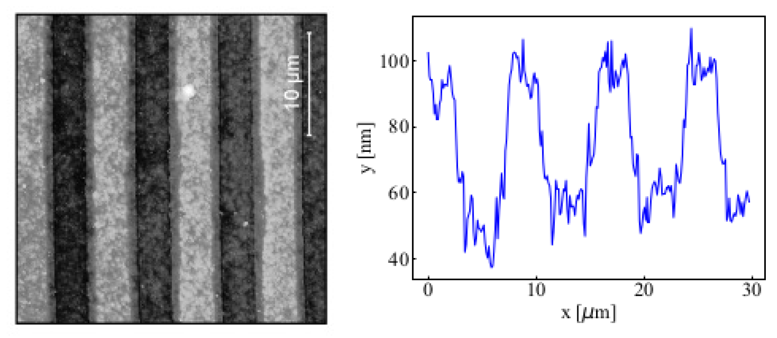
Profiles of gratings were analyzed with an atomic force microscope (AFM). A typical profile of an etched sample is shown in Figure 2. Let us note that the horizontal axis in the figure is compressed by a factor of about 500 with respect to the vertical one, which means that in the real perspective fluctuations of the etched profile are rather smooth and the roughness of the etched surface is equal to about 10 nm.
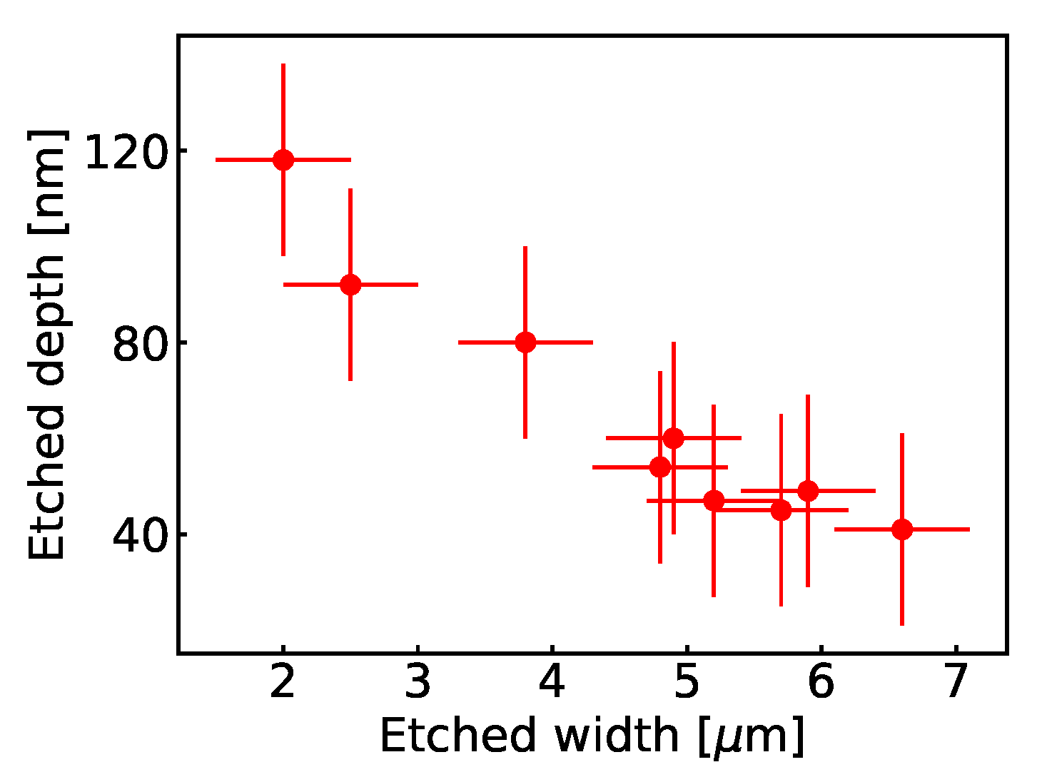
A detailed study of the process of etching showed that at a given time of etching, the depth of etched grooves is correlated to the their width, as it is shown in Figure 3. However, by changing the time of etching and composition of the etching mixture, we were able to produce gratings with given period and different depths. The wafer A (single QW) was used to prepare samples with the period of grating equal to 2 μ m, 4 μ m, 6 μ m and 8 μ m. The wafer B (two QWs) was used to prepare samples with etched grating period equal to 8 μ m and the width of grooves changing between 2 μ m and 6 μ m. For comparison, we used also samples prepared on the wafer B with a Au/Cr grating evaporated on their surface with the period equal to 2 μ m, 4 μ m, 6 μ m and 8 μ m. The thickness of metalization was equal to about 50 nm. As it was already shown in previous studies [33], a metalization of this thickness makes the metallic layer unpenetrable for THz radiation.

3. Results

3.1. Comparison of Etched and Au Gratings

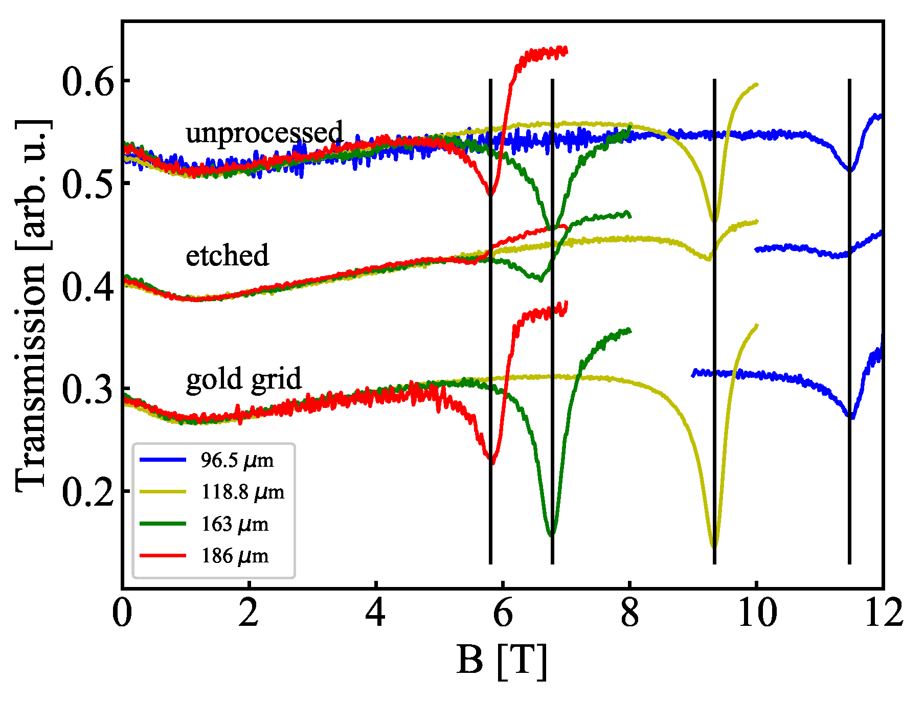
A set of transmission spectra through samples from the wafer with two QWs is shown in Figure 4. In unprocessed sample with no periodic structure on the surface, we observe signatures of the CR transition, indicated with vertical bars. Plotting positions (in B) of minima of the CR as a function of the energy of photons allowed us to estimate an effective electron mass to be equal to 0.103 m e , which is the same as that determined on other CdTe/CdMgTe QWs in previous studies [23,24].
Comparing results presented in this figure one can notice that in the case of the Au grating, the plasmonic shift is very small and in some cases its presence is not evident. On the other hand, it is quite well visible in the etched sample. Another general observation visible in Figure 4 concerns the shape of the lines which apperently carries features of a dispersive profile. We attribute this fact to interferences in the structure, an effect which was described long ago [34]. On the other hand, we cannot exclude a possible influence of diffraction of THz radiation on gratings on the lineshape since diffraction changes conditions of propagation of the radiation and thus contributes to the overall interference pattern. In the case of Au gratings, one could fabricate structures with different thickness of gratings. In the case of etched gratings, one could think about dry etching which should lead to more sharp profiles of etched grooves. Then, details of the diffractive structures could be modified and the impact of modifications on the lineshape could be studied.
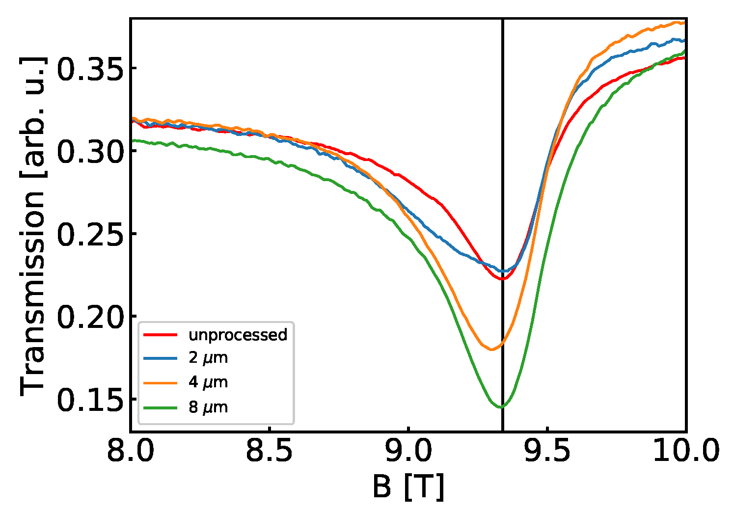
A clear plasmonic shift in Au-grating samples is visible in spectra with a grating of a shorter period, as it is presented in Figure 5. This is in accordance with Equation (A1) with k inversly proportional to the period of grating. Also, plasmonic resonances visible in the spectra of etched samples show the amplitude much smaller than that for other two types of samples. Below we show that the amplitude of the resonance is strongly dependent on the depths of grooves in the grating.

3.2. Dependence on the Grooves’ Depth

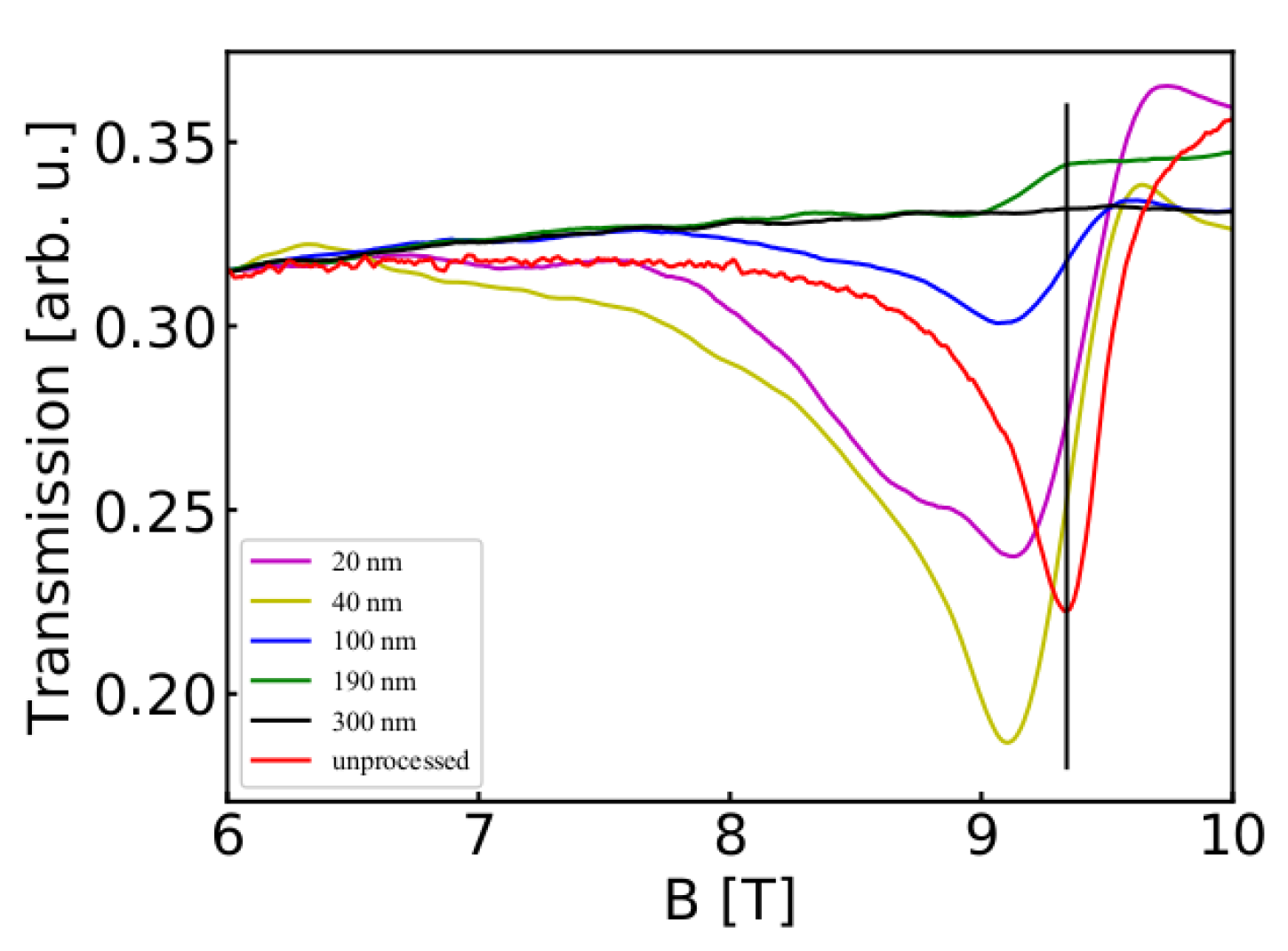
A series of samples was prepared on the wafer B (two QWs) with the grating period of 8 μ m, the same width of etched grooves equal to 3.2 μ m and the grooves’ depth equal to 20 nm, 40 nm, 100 nm, 190 nm and 300 nm. Let us recall that the QWs in the wafer B are positioned at 45 nm and 100 nm below the surface so etching to the depth of 100 nm cuts the upper QW and most probably strongly influences the lower one, and etching to 190 nm and 300 nm cuts both of them forming a structure similar to a grating composed of conducting stripes.
Transmission spectra for these samples are shown in Figure 6 and can be compared with transmission obtained on unprocessed sample, showing a spectrum of the CR. A shift due to plasmonic excitation is apparent for samples with etched gratings except for the deepest etching when there are no signatures of the resonant signal at all. This indicates that “conducting stripes” which are left after etching are practically depopulated of electrons. This gives us an important information concerning processing of CdTe-based structures that etching carried out in this study leads to depopulation of QWs of 2DEG. We propose that positively charged surface states are generated during etching and then neutralized with electrons from the QWs.
The curves for grooves of 20 nm, 40 nm and 100 nm show a minimum at the same magnetic field 9.12 T which we interpret as the signature of a plasmonic resonance which occurs in the lower QW. This interpretation is based on the fact that this value of B quite well corresponds to estimates based on Equations (1), (A1) and (A2) with material parameters of CdTe/CdMgTe QW [24] and n s given by magnetotransport measurements. However, with the shallowest depth of grooves equal to 20 nm, one clearly gets a resonance also at 8.68 T. At the moment, the origin of this resonance is not clear to us. It cannot be the second mode of the plasmon observed at 9.12 T because then it should have appeared at about 8.87 T. Clearly, at the moment there is not enough data to give a reliable interpretation of this resonance.

3.3. Influence of Illumination with the White Light

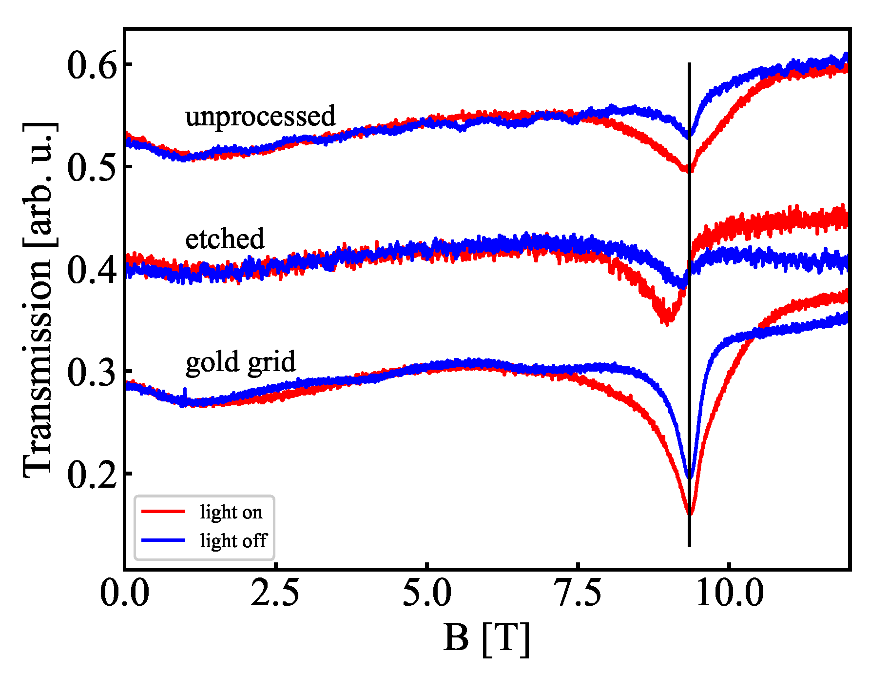
An influence of illumination with white light on transmission spectra was studied on unprocessed sample and samples with Au and etched grating of the period equal to 8 μ m. During the experiment, illumination of the sample was turned on for 15 min and then measurements started with the light on until the end of measurements. Results are presented in Figure 7. In general, illumination with white light leads to three effects: an increase of the amplitude of the signal, a broadening of the absorption line and—in the case of etched sample—a shift of the minimum of the transmission curve.
The spectra of the sample with Au grating are practically the same as in the unprocessed sample. It is intersting to note, however, that the amplitude of the plasmonic resonance is bigger in procecssed than in unprocessed sample; we will discuss this point in the next section. The reaction of etched sample is quite different: the plasmonic shift is equal to about 0.18 T in the dark and to about 0.5 T after illumination. This shows that plasmonic resonances in etched samples are tuneable with white light—an effect which can potentially be used in tuneable detectors.
We interpret the shifts of position of the resonance under illumination as resulting from the change of concentration of a 2DEG which take part in plasmonic excitations. A shift to lower B indicates an increase of the frequency of plasmon (see Eqsuations (1) and (A1)) which can be attributed to an increase of concentration of the 2DEG. This is consistent with an increase of concentration of the 2DEG given by an analysis of magnetotransport data registered after illumination.

4. Discussion

A few paths led us to the study described in this paper. The first one was to enlarge our previous research on plasmonic excitations in modulation doped single CdTe/CdMgTe quantum wells [23,24] to more complicated system. We decided to study a system with two QWs separated by a large distance of about 44 nm. Thus, we were not looking for effects of interaction of the wells. This distance is at least a few times bigger than that typically considered in Coulomb drag experiments [35]. In fact, in results of our measurements, we did not observe any feature which could be attributed to interaction of these two conducting layers at THz frequencies.
Second, we wanted to follow an idea put forward long ago by S. A. Mikhailov [36] who suggested that replacement of typically used metallic grating by a grating composed of quantum wires would lead to amplification of a plasmonic instability. The main argument behind this idea was to lower the frequency of plasmonic excitations in the grating towards the frequency of plasmonic waves in the quantum well. This could be achieved only by an essential reduction of concentration of electrons in the grating, i.e., by replacement a metal with a doped semiconductor. A practical realization of such a “quantum wire” grating leads to a structure with two quantum wells where the upper one is etched to form stripes with a 2DEG. A relatively big separation of the two QWs in wafer B resulted also from the idea of using the upper etched QW only as a “wire grating” for the lower QW.
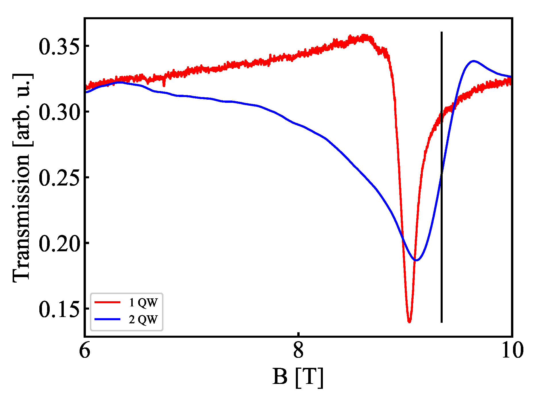
The most important result which could be addressed in connection with this reasoning is presented in Figure 8 which compares transmission spectra obtained on samples with one QW and two QWs on which gratings of a period of 8 μ m were etched (wafers A and B, respectively). The depth of etching of sample from both the wafer A (single QW) and B (two QWs) was 40 nm. The depth of etching in the case of the sample with two QW was chosen to not to depopulate the lower QW but to form conducting wires from the upper QW (compare Figure 6). Comparison of these two curves (after normalization) shows that the main difference is the width of the line which is essentially larger in the case of the sample with two QWs. Additionally, the amplitude of MP resonances (in absolute values, normalized to the power of laser only) in the case of two QW is about five times smaller than in the case of the single QW. This could result from a greater disorder in the case of two QWs with one of them cut by etching or from a generally lower concentration n s in samples after etching.
Although this result does not follow the expectations related to Mikhailov [36], we think that more research is necessary in this direction. In particular, one could think about etching samples with different separation of the QWs or to study other materials which would not show so strong depopulation of 2DEG with etching.
The fact that one obtains sharp plasmonic resonances in the case of etched grating on a single QW makes questionable the procedure of preparing a “wire grating” by etching the upper QW in a sample with two wells. The results show that plasmonic resonances appear just in a single QW and do not need conducting stripes. That is why, we suggest that to follow the idea presented in Mikhailov [36], one should look for other solutions. For example, one could try to process a grating made of graphene or a similar two-dimensional conducting material with concentration of electrons comparable to that of a 2DEG in the underlying quantum well.
Third, we aimed at a broad characterization of studied samples as resonant detectors of THz radiation which would be appropriate to work at high magnetic fields and low temperatures. We showed that, at least in some cases, the samples studied could serve for this purpose. On the other hand, one could also try to use samples with etched gratings as non-resonant (or broad band detectors), particularly with an additional illumination with white light. As it is shown in Figure 7 and Figure 8, the width of a plasmonic response can be equal to about 1 T which allows to detect radiation with frequency range of about 0.25 THz.
A broadening of the line under illumination is observed in all samples. According to theoretical considerations presented in Mikhailov [37], the width w of the resonance is a sum of two contributions: w = γ + Γ , where γ is a scattering decay while Γ is a radiative decay. However, as it is shown in Mikhailov [37], in the case of a 2DEG with a high electron mobility, Γ / γ σ 0 and Γ > > γ ; σ 0 is a static conductivity at B = 0. The last relation means that in fact w Γ due to a large value of σ 0 . Thus, one can conclude that broadening of the line is related to an increase of Γ which is consistent with the fact that conductivity of CdTe/CdMgTe QWs increases under illumination.
The results show that grating metamaterials presented in this work can be useful as magnetic field tuneable (quasi-) resonant detectors of THz radiation. Looking on transmission spectra presented above we find that a typical width of the resonant line is equal to about Δ B 0.4 T which corresponds to uncertainity of frequency equal to Δ f 0.12 THz (the relation between Δ B and Δ f is determined from ω c r = e B / m * ). However, in the case of etched grating on a single quantum well (Figure 8), Δ B 0.18 T which leads to Δ f 0.05 THz and Δ f / f 0.02. Let us also note that this detector shows a resonant line which is due to plasmonic excitations. Thus, it is a detector with a strong plasmonic response. Generally, this offers a broader possibility to tune the resonance (by geometry of the sample, influence of white light), in comparison with a detector based on the CR which response frequency is firmly fixed by the electron effective mass.
In conclusion, we carried out low-temperature magnetotransmission measurements on semiconductor metamaterials based on CdTe/CdMgTe modulation doped structures which formed one or two quantum wells with a 2DEG. The samples were equipped with Au or etched gratings. We showed that metamaterials studied showed a response to monochromatic THz radiation resulted from excitation of plasmons in two-dimensional quantum wells. By studying samples with etched gratings of different geometrical parameters we showed an influence of the etching process on depopulation of quantum wells. Also, we showed a strong response of plasmonic resonances to illumination of metamaterials with white light. A broad spectrum of response exhibited by samples with different parameters of grating allows us to propose such metamaterials as possible THz detectors and filters (both resonant and quasi-resonant) working at high magnetic fields, tuneable by magnetic field and white light.

Author Contributions

Conceptualization and methodology, D.Y. and J.Ł.; investigation D.Y., M.S., K.K., R.B., R.R., G.K., T.W. and J.W., writing—original draft preparation, review and editing, supervision, J.Ł. All authors have read and agreed to the published version of the manuscript.

Funding

This research was partially supported by Polish National Science Centre UMO-2015/17/B/ST7/03630 and UMO-2017/27/N/ST7/01771 grants and the Foundation for Polish Science through a TEAM/2016-3/25 and the IRA Programme co-financed by EU within SG OP (grants No. MAB/2017/1 and MAB/2018/19).

Conflicts of Interest

The authors declare no conflict of interest.

Abbreviations

The following abbreviations are used in this manuscript:
2DEGtwo-dimensional electron gas
AFMatomic force microscope
CRcyclotron resonance
EBLelectron beam lithography
MPmagnetoplasmon
PMMApolymethyl methacrylate
SEMscanning electron microscope
SPSLshort period superlattice
QWquantum well

Appendix A

The frequency ω p is the plasmon frequency at B = 0 and satisfies the following dispersion relation
ω p = n s e 2 k 2 m * ϵ 0 ϵ ( k ) ,
where k is the wave vector of the (magneto)plasmon. In the case of samples with gratings of the period Λ , plasmon wave vectors can take values equal to an integer multiplicity of 2 π / Λ . The effective dielectric constant ϵ ( k ) is a k-dependent function which allows to describe the electromagnetic environment of the 2DEG. There are two typical situations: when the 2DEG is ungated and when it is covered with a metallic gate. In these cases, one has
ϵ u g ( k ) = 1 2 ϵ 1 + ϵ 2 1 + ϵ 2 tanh ( k d ) ϵ 2 + tanh ( k d ) ,
and
ϵ g ( k ) = 1 2 ( ϵ 1 + ϵ 2 coth ( k d ) ) ,
respectively [38,39,40]. In these formulas, ϵ 1 and ϵ 2 is the dielectric constant of the quantum well and the barrier material, respectively, and d is the barrier thickness.
These formulas are derived under the assumption of a uniform and infinite 2DEG covered with a barrier and a metallic gate or a barrier only. In real situations, plasmons are typically observed in samples with metallic gratings which cover the 2DEG only partially. We have found that in all studied cases of a 2DEG in CdTe-, GaAs- and GaN-based structures [24,27,30], a very good description of experimentally determined dispersion relation was obtained with Equation (A1) and a dielectric constant equal to a weighted average of ϵ u g and ϵ g :
ϵ = α ϵ u g + ( 1 α ) ϵ g ,
where α is equal to the percentage of the period Λ not covered with metal. In the case of etched gratings, α will denote a fraction of the period Λ which was not etched.
On the other hand, we would like to stress that applicability of Equation (A4) must be limited since recent analitical considerations [41,42] show that this is rather the width of the metallic stripe, not the period of the grating, which determines the dispersion relation in a partially gated 2DEG.

References

  1. Dyakonov, M.; Shur, M.S. Shallow water analogy for a ballistic field effect transistor: New mechanism of plasma wave generation by dc current. Phys. Rev. Lett. 1993, 71, 2465–2468. [Google Scholar] [CrossRef]
  2. Dyakonov, M.; Shur, M.S. Detection, mixing, and frequency multiplication of terahertz radiation by two-dimensional electronic fluid. IEEE Trans. Electron Devices 1996, 43, 380–387. [Google Scholar] [CrossRef]
  3. Knap, W.; Teppe, F.; Meziani, Y.; Dyakonova, N.; Łusakowski, J.; Boeuf, F.; Skotnicki, T.; Maude, D.; Rumyantsev, S.; Shur, M.S. Plasma wave detection of sub-terahertz and terahertz radiation by silicon field-effect transistors. Appl. Phys. Lett. 2004, 85, 675–677. [Google Scholar] [CrossRef] [Green Version]
  4. Ikamas, K.; Cibiraite, D.; Lisauskas, A.; Bauer, M.; Krozer, V.; Roskos, H.G. Broadband terahertz power detectors based on 90-nm silicon CMOS transistors with flat responsivity up to 2.2 THz. IEEE Electron Device Lett. 2018, 39, 1413–1416. [Google Scholar] [CrossRef]
  5. Muravev, V.A.; Gusikhin, P.A.; Zarezin, A.M.; Andreev, I.V.; Gubarev, S.I.; Kukushkin, I.V. Two-dimensional plasmon induced by metal proximity. Phys. Rev. B 2019, 99, 241406. [Google Scholar] [CrossRef] [Green Version]
  6. Shchepetilnikov, A.V.; Kaysin, B.D.; Gusikhin, P.A.; Muravev, V.M.; Tsydynzhapov, G.E.; Nefyodov, Y.A.; Dremin, A.A.; Kukushkin, I.V. Optimization of the frequency response of a novel GaAs plasmonic terahertz detector. Opt. Quantum Electron. 2019, 51, 1–8. [Google Scholar] [CrossRef]
  7. Bandurin, D.A.; Svintsov, D.; Gayuchenko, I.; Shuigang, G.X.; Principi, A.; Moskotin, M.; Tretyakov, I.; Yagodkin, D.; Zhukov, S.; Taniguchi, T.; et al. Resonant terahertz detection using graphene plasmons. Nat. Commun. 2018, 9, 5392. [Google Scholar] [CrossRef]
  8. Knap, W.; Dur, D.; Raymond, A.; Meny, C.; Leotin, J.; Huant, S.; Etienne, B. A far-infrared spectrometer based on cyclotron resonance emission sources. Rev. Sci. Instr. 1992, 63, 3293–3297. [Google Scholar] [CrossRef]
  9. Knap, W.; Łusakowski, J.; Parenty, T.; Bollaert, S.; Cappy, A.; Popov, V.V.; Shur, M.S. Terahertz emission by plasma waves in 60 nm gate high electron mobility transistors. Appl. Phys. Lett. 2004, 84, 2331–2333. [Google Scholar] [CrossRef] [Green Version]
  10. Knap, W.; Łusakowski, J.; Karpierz, K.; Orsal, B.; Robert, J.-L. Improved performance of magnetically tunable GaAs and InP far-infrared detectors. J. Appl. Phys. 1992, 72, 680–683. [Google Scholar] [CrossRef]
  11. Yavorskiy, D.; Karpierz, K.; Grynberg, M.; Knap, W.; Łusakowski, J. Indium antimonide detector for spectral characterization of terahertz sources. J. Appl. Phys. 2018, 123, 064502. [Google Scholar] [CrossRef]
  12. Białek, M.; Witowski, A.M.; Orlita, M.; Potemski, M.; Czapkiewicz, M.; Wróbel, J.; Umansky, V.; Grynberg, M.; Łusakowski, J. Plasmonic terahertz detectors based on a high-electron mobility GaAs/AlGaAs heterostructure. J. Appl. Phys. 2014, 115, 214503. [Google Scholar] [CrossRef] [Green Version]
  13. Grynberg, M.; Huant, S.; Martinez, G.; Kossut, J.; Wojtowicz, T.; Karczewski, G.; Shi, J.-M.; Peeters, F.M.; Devreese, J.T. Magneto-polaron effect on shallow indium donors in CdTe. Phys. Rev. B 1996, 54, 1467–1470. [Google Scholar] [CrossRef] [PubMed]
  14. Höschl, P.; Polívka, P.; Prosser, V.; Skárivxaxnkovxax, M.; Vidra, M. Cadmium Telluride nuclear radiation detectors. Jpn. J. Appl. Phys. 1977, 16, 279–281. [Google Scholar] [CrossRef]
  15. Dornhaus, R.; Nimtz, G. The properties and applications of the Hg1−xCdxTe alloy systems. In Narrow—Gap Smiconductors; Höhler, G., Ed.; Springer: Berlin/Heidelberg, Germany, 1985. [Google Scholar]
  16. Duplantier, B.; Rivasseae, V.; Fuchs, J.N. (Eds.) Dirac Matter; Progress in Mathematical Physics; Springer International Publishing: Cham, Switzerland, 2017; Volume 71. [Google Scholar]
  17. Shen, S.-Q. Topological Insulators, 2nd ed.; Springer Series in Solid-State Sciences; Keimer, K., Merlin, R., Queisser, H.-J., von Klitzing, K., Eds.; Springer Nature Singapore Pte Ltd.: Singapore, 2017; Volume 187. [Google Scholar]
  18. Zawadzki, W. Semirelativity in semiconductors: A review. J. Phys. Condens. Matter 2017, 29, 373004. [Google Scholar] [CrossRef] [Green Version]
  19. Gałązka, R.R.; Wojtowicz, T. CdTe-based semimagnetic semiconductors. In CdTe and Related Compounds; Physics, Defects, Hetero- and Nano-Structures, Crystal Growth, Surfaces and Applications, Part I; Triboulet, R., Siffert, P., Eds.; Elsevier: Amsterdam, The Netherlands, 2010; pp. 133–168. [Google Scholar]
  20. Kobak, J.; Smoleński, T.; Goryca, M.; Papaj, M.; Gietka, K.; Bogucki, A.; Koperski, M.; Rousset, J.-G.; Suffczyński, J.; Janik, E.; et al. Designing quantum dots for solotronics. Nat. Commun. 2014, 5, 3191. [Google Scholar] [CrossRef] [Green Version]
  21. Piot, B.A.; Kunc, J.; Potemski, M.; Maude, D.K.; Betthausen, C.; Vogl, A.; Weiss, D.; Karczewski, G.; Wojtowicz, T. Fractional quantum Hall effect in CdTe. Phys. Rev. B 2010, 82, 081307. [Google Scholar] [CrossRef] [Green Version]
  22. Furdyna, J.K.; Lee, S.; Dobrowolska, M.; Wojtowicz, T.; Liu, X. Band-Offset Engineering in Magnetic/Non-Magnetic Semiconductor Quantum Structures. In Introduction to the Physics of Diluted Magnetic Semiconductors; Springer Series in Materials Science; Kossut, J., Gaj, J., Eds.; Springer: Berlin/Heidelberg, Germany, 2010; pp. 103–160. [Google Scholar]
  23. Grigelionis, I.; Białek, M.; Grynberg, M.; Czapkiewicz, M.; Kolkovskiy, V.; Wiater, M.; Wojciechowski, T.; Wróbel, J.; Wojtowicz, T.; Diakonova, N.; et al. Terahertz magneto-spectroscopy of a point contact based on CdTe/CdMgTe quantum well. J. Nanophotonics 2015, 9, 093082. [Google Scholar] [CrossRef]
  24. Grigelionis, I.; Nogajewski, K.; Karczewski, G.; Wojtowicz, T.; Czapkiewicz, M.; Wróbel, J.; Boukari, H.; Mariette, H.; Łusakowski, J. Magnetoplasmons in high electron mobility CdTe/CdMgTe quantum wells. Phys. Rev. B 2015, 91, 075424. [Google Scholar] [CrossRef]
  25. Imanaka, Y.; Takamasu, T.; Kido, G.; Karczewski, G.; Wojtowicz, T.; Kossut, J. Cyclotron resonance in high mobility CdTe/CdMgTe 2D electron system in the integer quantum Hall regime. Phys. B Condens. Matter 1998, 457, 256–258. [Google Scholar] [CrossRef]
  26. Karczewski, G.; Wojtowicz, T.; Wang, Y.; Wu, X.; Peeters, F. Electron effective mass and resonant polaron effect in CdTe/CdMgTe quantum wells. Phys. Status Solidi B 2002, 229, 597–600. [Google Scholar] [CrossRef]
  27. Białek, M.; Czapkiewicz, M.; Wróbel, J.; Umansky, V.; Łusakowski, J. Plasmon dispersions in high electron mobility terahertz detectors. Appl. Phys. Lett. 2014, 104, 263514. [Google Scholar] [CrossRef]
  28. Białek, M.; Łusakowski, J.; Czapkiewicz, M.; Wróbel, J.; Umansky, V. Photoresponse of a two-dimensional electron gas at the second harmonic of the cyclotron resonance. Phys. Rev. B 2015, 91, 045437. [Google Scholar] [CrossRef] [Green Version]
  29. Nogajewski, K.; Łusakowski, J.; Knap, W.; Popov, V.V.; Teppe, F.; Rumyantsev, S.L.; Shur, M.S. Localized and collective magnetoplasmon excitations in AlGaN/GaN-based grating-gate terahertz modulators. Appl. Phys. Lett. 2011, 99, 213501. [Google Scholar] [CrossRef]
  30. Łusakowski, J. Plasmon—Terahertz photon interaction in high-electron-mobility heterostructures. Semicond. Sci. Technol. 2016, 32, 013004. [Google Scholar] [CrossRef]
  31. Kushvaha, M.S. Plasmons and magnetoplasmons in semiconductor heterostructures. Surf. Sci. Rep. 2001, 41, 1–416. [Google Scholar] [CrossRef]
  32. Bobko, E.; Płoch, D.; Wiater, M.; Wojtowicz, T.; Wróbel, J. Fabrication of CdMgTe/Cd(Mn)Te nanostructures with the application of high-resolution electron-beam lithography. Opto-Electron. Rev. 2017, 25, 65–68. [Google Scholar] [CrossRef]
  33. Szczytko, J.; Stolarek, M.; Piętka, B.; Łusakowski, J.; Barańska, A.; Papis, E.; Wawro, A.; Adomavisius, R.; Krotkus, A.; Pałka, N.; et al. Terahertz properties of metallic layers and grids. In Proceedings of the 19th International Conference on Microwaves, Radar and Wireless Communications—MIKON 2012, Warsaw, Poland, 21–23 May 2012; pp. 271–275. [Google Scholar]
  34. Von Ortenberg, M. Substrate effects on the cyclotron resonance in surface layers of Silicon. Solid State Commun. 1975, 17, 1335–1338. [Google Scholar] [CrossRef]
  35. Narozhyny, B.N.; Levchenko, A. Coulomb drag. Rev. Mod. Phys. 2016, 88, 025003. [Google Scholar] [CrossRef] [Green Version]
  36. Mikhailov, S.A. Plasma instability and amplification of electromagnetic waves in low-dimensional electron system. Phys. Rev. B 1998, 58, 1517–1532. [Google Scholar] [CrossRef] [Green Version]
  37. Mikhailov, S.A. Microwave-induced magnetotransport phenomena in two-dimensional electron systems: Importance of electrodynamic effects. Phys. Rev. B 2004, 70, 165311. [Google Scholar] [CrossRef] [Green Version]
  38. Eguiluz, A.; Lee, T.K.; Quinn, J.J.; Chiu, K.W. Interface excitations in metal-insulator-semiconductor structures. Phys. Rev. B 1975, 11, 4989–4993. [Google Scholar] [CrossRef]
  39. Chaplik, A.V. Possible crystalization of charge carriers in low-dimensional inversion layers. Sov. Phys. JETP 1972, 35, 395–398. [Google Scholar]
  40. Popov, V.V. Plasmon Excitation and Plasmonic Detection of Terahertz Radiation in the Grating-Gate Field-Effect-Transistor Structures. J. Infrared Mill. Terahz. Wave 2011, 32, 1178–1191. [Google Scholar] [CrossRef]
  41. Zabolotnykh, A.A.; Volkov, V.A. Interaction of gated and ungated plasmons in two-dimensiona electron systems. Phys. Rev. B 2019, 99, 165304. [Google Scholar] [CrossRef] [Green Version]
  42. Bylinkin, A.; Totova, E.; Mikheev, V.; Zhukova, E.; Zhukov, S.; Belyanchikov, M.; Kashchenko, M.; Miakonkikh, A.; Svintsov, D. Tight-binding terahertz plasmon in chemical-vapor-deposited graphene. Phys. Rev. Appl. 2019, 11, 054017. [Google Scholar] [CrossRef] [Green Version]
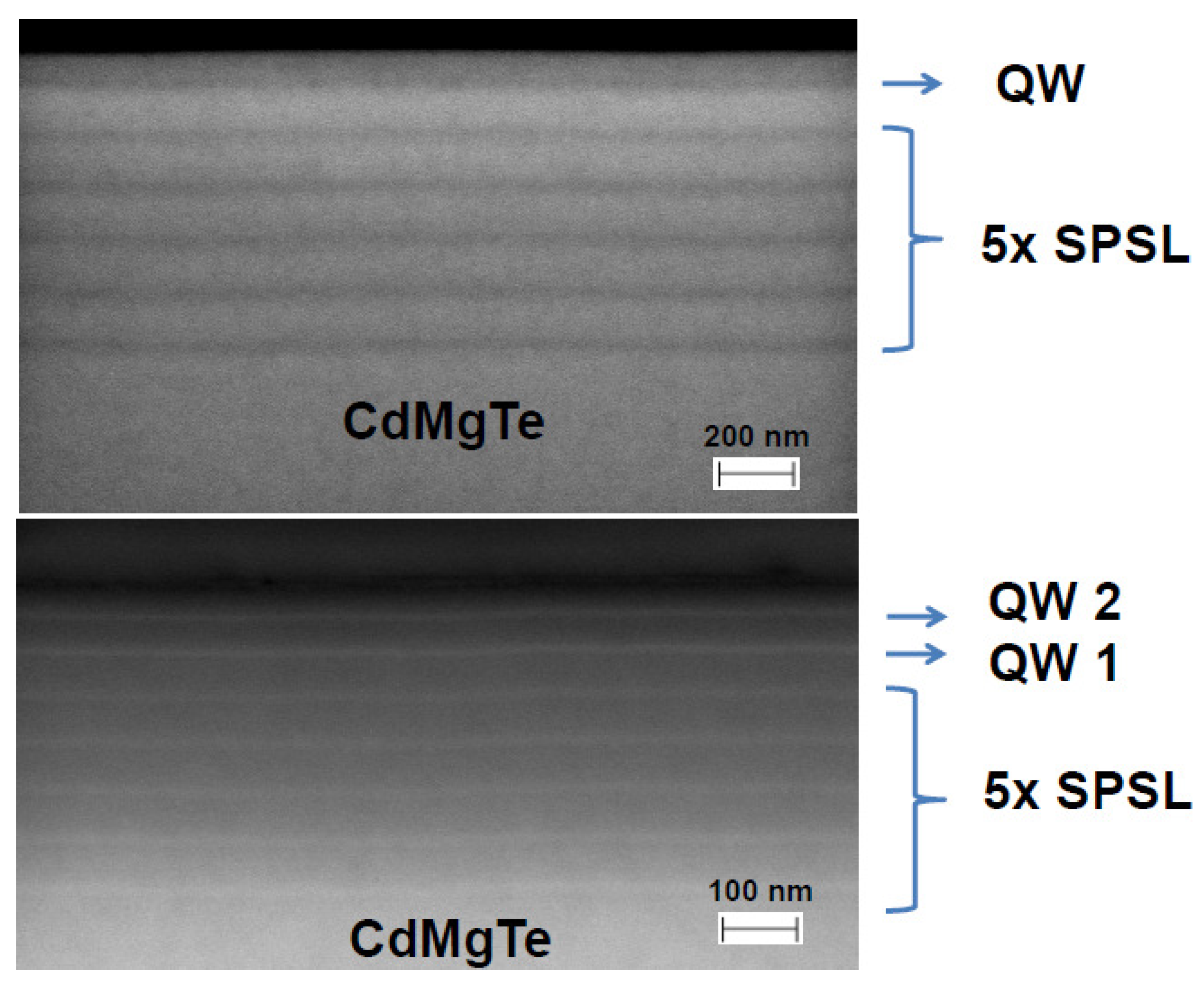
Figure 1. SEM photographs of the layered structure of the wafer A with one QW (top) and the wafer B with two QWs (bottom).
Applsci 10 02807 g001
Figure 2. An electron microscope photography of etched sample (left) with a corresponding AFM profile (right); x and y coordinates describe, respectively, position of the tip of AFM in the plane of the sample and in the direction normal to this plane.
Applsci 10 02807 g002
Figure 3. A dependence of the depth of etched grooves on their width at a constant time of etching equal to 60 s. Error bars show uncertainity given by measurements with the AFM.
Applsci 10 02807 g003
Figure 4. Transmission spectra of samples from the wafer B. In the case of both etched and Au gratings, the period of the grating was equal to 8 μ m and α 0.5 (see Appendix A for a definition of α ). Vertical bars indicate the position of the CR. The wavelenght of radiation used is indicated in the figure.
Applsci 10 02807 g004
Figure 5. Transmission spectra through samples from wafer B with Au gratings of the period equal to 8 μ m, 4 μ m and 2 μ m (bottom to top) and α 0.5 . A reference unprocessed sample shows the position of the CR (indicated with a vertical bar). The wavelength of radiation was 118.8 μ m.
Applsci 10 02807 g005
Figure 6. Influence of depth of grooves on transmission. The wavelenght of radiation was 118.8 μ m. Position of the CR in unprocessed sample is indicated with a vertical bar.
Applsci 10 02807 g006
Figure 7. Influence of illumination with white light on transmission spectra on unprocessed sample and samples with Au and etched grating of the period equal to 8 μ m. The wavelenght of radiation was 118.8 μ m. The vertical bar shows position of the CR in unprocessed sample.
Applsci 10 02807 g007
Figure 8. Transmission spectra of samples with etched grating of the period equal to 8 μ m: single and two quantum wells. The wavelenght of radiation was 118.8 μ m. The vertical bar indicated position of the CR in unprocessed sample.
Applsci 10 02807 g008