Abstract
Globally, more and more attention has been paid to the integrity of Girth Welds (GW) of oil and gas pipelines due to their failures with high consequences. A primary concern is that defects originate during field construction but over time may be subject to external loads due to earth movement. GW defects in newly built pipelines are also assumed to exist but would be much smaller in size, and more difficult to detect, which motivated the investigation into minimum defect detection capabilities of the inspection technologies. This study presents the evaluation results of UltraScan™ Circumferential Crack-Like Detection (USCCD) technology for oil pipeline GW inspection, based upon the pull test and in field data from Inline Inspection (ILI) of pipeline by PetroChina Pipeline Company (PPC) using GE PII (General Electric Company, Pipeline Integrity Inspection) 32” UltraScan™ CCD Tool. The performance of USCCD is given according to the ILI data, pull test results and dig NDE (Non-Destructive Examination). It can be concluded that crack-like defects with clear edges can be detected during ultrasonic propagation; however, the irregular shape of weld makes the inspection more difficult. It is still a challenge to identify the type of defects, and depth sizing can only be classified not quantified, which would require more excavations. However, this technology is feasible for the alternative technology of GW defect inspection.
1. Introduction
Girth Welds (GWs) of oil and gas pipelines are more and more concerning because of frequent failures and the accompanying high consequences [1]. They are always the weak points of the pipelines due to the field joining and worsened laying locations because of limited right-of-way. GW defects of newly built pipelines are much narrower, which challenges the traditional ILI technologies and analyzing methods when detecting, and are more dangerous because of higher diameters and pressures [2,3].
As conventional MFL (Magnetic Flux Leakage) is universally used in the industry and qualitatively known to be sensitive to volumetric metal loss [4,5,6], ultrasonic crack detection is a superior method for cracks and crack-like defects, because it is more sensitive to defect edges that are close to each other [7,8,9,10]. The objective of this test was to evaluate and quantify the performance for UltraScan Circumferential Crack-Like Detection (USCCD) technology, based upon the pull test and in field data by PetroChina Pipeline Company (PPC) using GE PII 32” UltraScan™ CCD Tool.
2. Setup and Execution of Pull Tests
2.1. Ultrasonic Measurement Tool
The UltraScan™ CCD pipeline inspection tool consists of several vehicles connected by linkage towbars as shown in Figure 1.
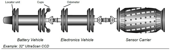
Figure 1.
UltraScan™ CCD Inspection Tool.
The electronics vehicle contains the ultrasound instrumentation units. Each of these units collects and processes data from ultrasound sensors acting as both transmitters and receivers. The ultrasound signals received are amplified, digitized and stored.
The inspection itself is accommodated by a high-density ring of ultrasonic sensors on a specially designed highly flexible polyurethane sensor carrier which guides the sensors along the pipe wall at a constant distance and orientation to the pipe wall.
The sensor carrier is designed such that the entire pipe circumference is redundantly inspected in a single run. For 32” pipe diameters, 512 sensors are mounted on 16 skids that are used for the crack detection with 240 sensors inspecting in upstream and 240 in downstream direction. This configuration results in a distance between sensors in circumferential direction of approximately 10 mm which provides a sufficient overlap of neighboring ultrasonic sensor tracks. This design ensures that signal reflectors are detected redundantly and can be distinguished from possible geometrical indications. Additionally, each of the 16 skids features two perpendicular ultrasonic sensors to provide a measure of the spool’s wall thickness and localize the position of indications found with respect to the typical pipeline features as reliably as possible.
2.2. Description of Test Coupons Used
A variety of internal and external artificial defects (see Figure 2 and Appendix A) were manufactured by EDM (Electrical Discharge Machining) into the coupons (see Figure 3), located both upstream and downstream of the GWs’ surface (at weld), as well as in the center of the GWs’ surface (in weld), in order to test the inspection performance for sensitivity and repeatability. Test pipe is of X65 steel with outside diameter of 813 mm. Altogether 12 coupons were manufactured. Nominal Wall Thickness (WT) is 14.5 mm for all spools, apart from one spool which was 12.5 mm for WT change.
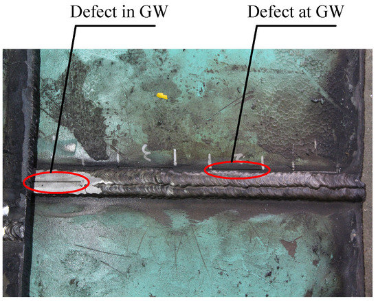
Figure 2.
Set of test notches with different depths and lengths.
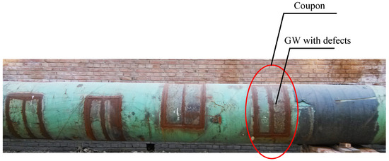
Figure 3.
Circumferential crack-like pieces.
2.3. Description of Pull Testing
Diagrams of the pull test facility are shown in Figure 4. The Inline Inspection (ILI) tool is placed in the launch tray in full operation mode and connected with the pulling rope. The liquid level is high enough to ensure that the interior of the test pipe is completely filled with water. A series of 10 pull-throughs was executed to validate repeatability and reproducibility at the speed of approximately 0.1 m/s~0.5 m/s. Pictures of the facility are shown in Figure 5.
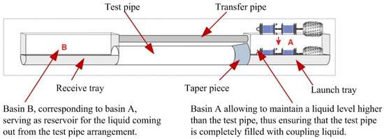
Figure 4.
Description of UltraScan™ Circumferential Crack-Like Detection (USCCD) pull test facility.
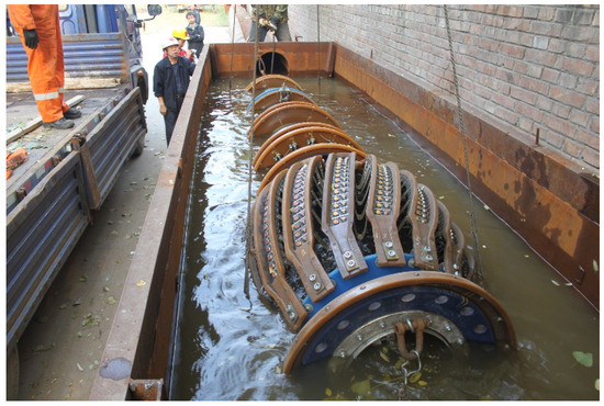
Figure 5.
Pull test pipe facility and tool.
91.4% of the maximum amplitude ranges are within the 2 dB range. This shows a good reproducibility of the measurements. The standard deviation is within a 1 dB range in 93.2% of the cases and confirms the reproducibility of the data.
3. USCCD Pull Test Results for GW Circumferential Crack-Like Defects
3.1. POD (Probability of Detection) and POI (Probability of Identification)
For determination of POD, 102 defects with open width of 0.8mm were taken into account. The test defects were categorized with respect to their position relative to the weld into two groups: defects in weld and those at weld. It was observed that the defect signals in weld and at weld show a different behavior regarding their amplitudes. This behavior was considered in the derivation of the depth sizing models for the different defect groups, respectively. Therefore, the POD, POI and sizing accuracies are calculated individually for each group of defects.
From the 36 defects present in weld, 35 were detected, which corresponds to a detection rate of 97%. For the defects present at weld, the detection rate is 92% (61 defects were detected from 66). See Table 1.

Table 1.
Probability of Detection (POD) summary of test results of Girth Weld (GW) crack-like defects.
All of the six defects that were missed are 1 mm deep, in which four are external. Hence, shallow cracks are more difficult to detect by USCCD. Because of the irregular shape of weld, external defects at weld tend to be a little more difficult to figure out.
At this stage of development, reliable guidelines for circumferential crack detection are not established to the extent to be able to distinguish between different types of defects in the pipeline (i.e., cracks and notches have similar reflection characteristics). Therefore, a “linear indication” was defined as a reportable defect type for circumferential crack detection.
All detected defects were classified as linear indications. The radial position (interior or exterior) was correctly classified for all defects detected in the test data.
3.1.1. Depth Sizing Accuracy
Depth of defects can be reported only in two classes: <2.5 mm and ≥2.5 mm. For defects ≥1 mm (axial opening) × 40 mm (circ.) in the GW, all of which are made as external, the depth estimation accuracies were achieved as listed in Table 2. For defects ≥1 mm (axial opening) × 40 mm (circ.) at the GW, the depth estimation accuracies were achieved as listed in Table 3. As the data analysis shows, all of the defects of 4 mm depth can be correctly classified in depth class ≥2.5 mm; while most defects of 1 and 2 mm deep were overestimated, especially for those in welds.
Table 2.
Depth sizing accuracy of defects in weld.
Table 3.
Depth sizing accuracy of defects at weld.
3.1.2. Length Sizing Accuracy
For defects in the GW, the following length estimation accuracies were achieved (Table 4). For defects at the GW, the following length estimation accuracies were achieved (Table 5). There is no big difference between these two groups. However, group of in weld shows more stable accuracy.
Table 4.
Length sizing accuracy of defects in weld.
Table 5.
Length sizing accuracy of defects at weld.
4. Real Operational Run & Excavation Results and Analysis
Thirty-two-inch crude oil pipeline was inspected by the UltraScan™ CCD inspection tool of PII Pipeline Solutions. The analysis team prepared the first five inspection sheets that were considered to contain the most significant indications found in the ILI data during the course of ILI data analysis and needed excavations to help improving analysis of the UltraScan™ CCD ILI data. The reported external defects were found to be in all weld repairs during the first five excavations, as shown in Table 6 and Figure 6, Figure 7, Figure 8, Figure 9, Figure 10, Figure 11 and Figure 12.
Table 6.
Excavation results of the first five digs.
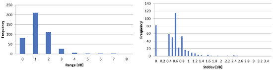
Figure 6.
Distribution of the maximum amplitude range and standard deviation over pull series.
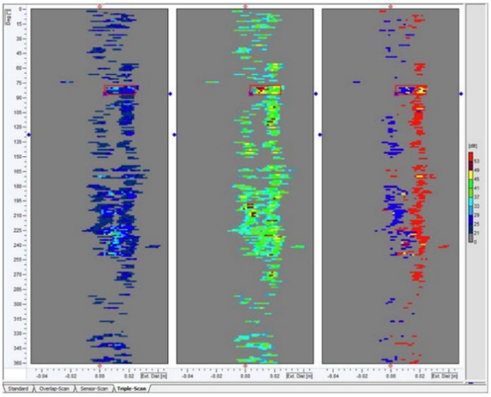
Figure 7.
Signal of GW 7050.
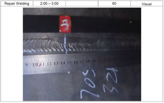
Figure 8.
Picture of GW 7050.
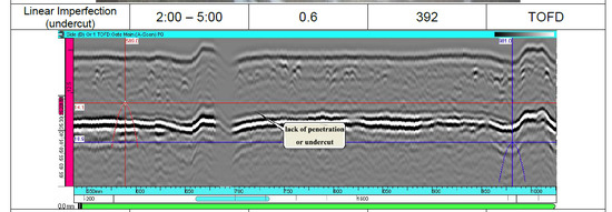
Figure 9.
TOFD (Time of Flight Diffraction) of GW 7050.
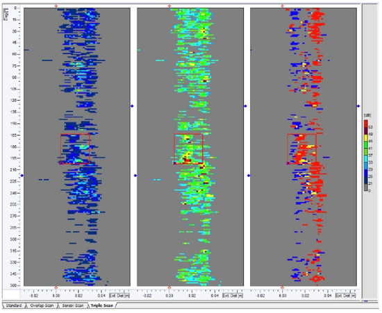
Figure 10.
Signal of GW 18540.
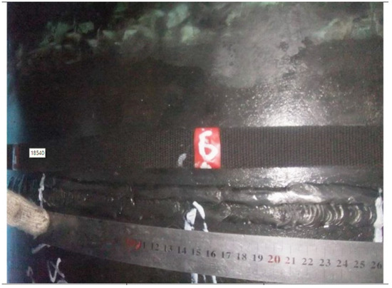
Figure 11.
Picture of GW 18540.
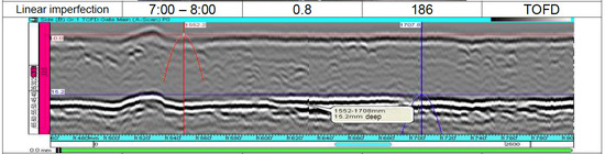
Figure 12.
TOFD of GW 18540.
PPC identified that internal defects are of priority interest. Another two locations, GW 10340 and GW 27640 were selected for excavation. Additionally, PPC also selected a base material feature in GW 17720 for excavation (see Figure 13). For these three dig results are shown in Table 7. Picture of gouge in GW 17720 base metal is shown in Figure 14.
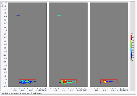
Figure 13.
Signal of gouge in GW 17720 base metal.
Table 7.
Excavation results of the second five digs.
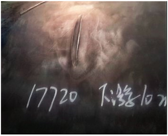
Figure 14.
Picture of gouge in GW 17720 base metal.
PPC carried out two further dig verifications on reported “linear indications” with NDE results shown in Table 7.
The primary observations and learnings resulted from the comparison of dig verifications (NDE results) and UltraScan™ CCD data focused on distinguishing features between the internal and external surfaces as a result of the high number of external weld-related anomalies identified.
For features on the external surface, the UltraScan™ CCD signals from the external features in the inspection data would not be distinguished from the signals received from the weld repairs as based on the rules derived from pull-throughs. Five areas were excavated for external linear indications and all were confirmed as weld repairs. Without a significant number of verified external cracks, no distinction can be made in the analysis of UltraScan™ CCD inspection data between weld repairs and linear indications or other weld defects (including but not limited to lack of fusion or metal loss of welding cap).
For features on the internal surface, the characteristic of UltraScan™ CCD weld reflection signals in the inspection data was also different from the weld reflection signals obtained from pull-throughs. The weld reflections in the pipeline are very heterogeneous with large variations in signal amplitude and weld geometry.
Various efforts were made to find particularities in the signals that could give hints to internal weld features. Two digs were initiated, one successful (GW 10340), one with nothing found (GW 27640).
The review of all 10 verified features reported as linear indications in the UltraScan™ CCD inspection resulted in the following:
- (1)
- Five features were found to be weld repairs;
- (2)
- One feature was found to be a linear imperfection (inclusion);
- (3)
- One feature was found to be an inclusion;
- (4)
- One feature was found to be a scratch;
- (5)
- One feature was found to be an indent of the weld cap;
- (6)
- One feature was not found in the field.
The analysis of UltraScan™ CCD tool data for the 32” pipeline and the review of the NDE field excavation data lead to the conclusion that there are still some uncertainties in the discrimination between reportable and non-reportable features.
Possible ways to improve the tool performance shall be assessed, and would require additional excavations.
5. Conclusions
The conclusions made, arising from the pull testing program and the inspection performance of the UltraScan™ CCD inspection system, were:
Crack-like defects can be detected as the clear edges can be found during ultrasonic propagation; however, shallow edges are easily to be missed.
The achieved POI includes the possibility to recognize linear indications as well as to classify the correct radial position of the defects. It was not investigated whether the type of defect (including crack-like, metal loss, weld geometry etc.) can be distinguished from the linear indication.
So far, the defect depth can only be classified and cannot be quantified for the defects in and at the weld. All of the defects with depths of ≥2.5 mm can be correctly classified; while most shallow ones were overestimated, especially for those in welds. The dynamic behavior of the sensor carrier potentially had an effect on the test data and the depth estimation. Furthermore, the different weld geometry led to lift-off in the tests. Therefore, the depth sizing specification might be compromised.
Real run inspection data analysis is more difficult than pull test, which shows lower accuracy. Possible reasons may include: much more irregular shape of weld, tool running speed, environment impact on tool dynamic performance, etc. Possible ways to improve the tool performance shall be assessed, and would require additional excavations.
Author Contributions
Conceptualization, L.S.D., Q.S.F., J.S. and D.P.W.; methodology, Q.S.F. and J.S.; validation, X.Q.X., T.W. and Z.J.W.; formal analysis, L.S.D.; investigation, L.S.D. and X.Q.X.; resources, Q.S.F.; data curation, L.S.D.; writing—original draft preparation, L.S.D.; writing—review and editing, T.W.; project administration, Q.S.F.; funding acquisition, Q.S.F. All authors have read and agreed to the published version of the manuscript.
Funding
This research was funded by the National Key Research and Development Program of China [Grant No. 2016YFC0802100] and Pipeline Research Council International (PRCI) [Grant No. PR-469-143708].
Conflicts of Interest
The authors declare no conflict of interest.
Appendix A
Table A1.
Parameters of defects with detected results.
Table A1.
Parameters of defects with detected results.
| No. | Length [mm] | Width [mm] | Depth [mm] | Relative Position | Radial Position | Coupon No. | Comment | Detected |
|---|---|---|---|---|---|---|---|---|
| P1 | 40 | 0.8 | 1 | at gw | ext | 1 | USCCD * | |
| P2 | 40 | 0.8 | 2 | at gw | ext | 1 | USCCD * | |
| P3 | 40 | 0.8 | 4 | at gw | ext | 1 | USCCD | |
| P4 | 40 | 0.8 | 1 | in gw | ext | 1 | USCCD * | |
| P5 | 40 | 0.8 | 2 | in gw | ext | 1 | USCCD * | |
| P6 | 40 | 0.8 | 4 | in gw | ext | 1 | USCCD | |
| P7 | 40 | 0.8 | 1 | at gw | int | 1 | ||
| P8 | 40 | 0.8 | 2 | at gw | int | 1 | USCCD | |
| P9 | 40 | 0.8 | 4 | at gw | int | 1 | USCCD | |
| P10 | 50 | 0.8 | 1 | at gw | ext | 2 | USCCD * | |
| P11 | 50 | 0.8 | 2 | at gw | ext | 2 | USCCD * | |
| P12 | 50 | 0.8 | 4 | at gw | ext | 2 | USCCD | |
| P13 | 50 | 0.8 | 1 | in gw | ext | 2 | USCCD * | |
| P14 | 50 | 0.8 | 2 | in gw | ext | 2 | USCCD * | |
| P15 | 50 | 0.8 | 4 | in gw | ext | 2 | USCCD | |
| P16 | 50 | 0.8 | 1 | at gw | int | 2 | ||
| P17 | 50 | 0.8 | 2 | at gw | int | 2 | USCCD * | |
| P18 | 50 | 0.8 | 4 | at gw | int | 2 | USCCD | |
| P19 | 40 | 0.8 | 1 | at gw | ext | 3 | 2 mm misalign | |
| P20 | 40 | 0.8 | 2 | at gw | ext | 3 | 2 mm misalign | USCCD * |
| P21 | 40 | 0.8 | 4 | at gw | ext | 3 | 2 mm misalign | USCCD |
| P22 | 40 | 0.8 | 1 | in gw | ext | 3 | 2 mm misalign | USCCD * |
| P23 | 40 | 0.8 | 2 | in gw | ext | 3 | 2 mm misalign | USCCD * |
| P24 | 40 | 0.8 | 4 | in gw | ext | 3 | 2 mm misalign | USCCD |
| P25 | 40 | 0.8 | 1 | at gw | int | 3 | 2 mm misalign | USCCD * |
| P26 | 40 | 0.8 | 2 | at gw | int | 3 | 2 mm misalign | USCCD * |
| P27 | 40 | 0.8 | 4 | at gw | int | 3 | 2 mm misalign | USCCD |
| P28 | 50 | 0.8 | 1 | at gw | ext | 4 | 2 mm misalign | USCCD |
| P29 | 50 | 0.8 | 2 | at gw | ext | 4 | 2 mm misalign | USCCD * |
| P30 | 50 | 0.8 | 4 | at gw | ext | 4 | 2 mm misalign | USCCD |
| P31 | 50 | 0.8 | 1 | in gw | ext | 4 | 2 mm misalign | USCCD * |
| P32 | 50 | 0.8 | 2 | in gw | ext | 4 | 2 mm misalign | USCCD * |
| P33 | 50 | 0.8 | 4 | in gw | ext | 4 | 2 mm misalign | USCCD |
| P34 | 50 | 0.8 | 1 | at gw | int | 4 | 2 mm misalign | USCCD |
| P35 | 50 | 0.8 | 2 | at gw | int | 4 | 2 mm misalign | USCCD * |
| P36 | 50 | 0.8 | 4 | at gw | int | 4 | 2 mm misalign | USCCD |
| P37 | 40 | 0.8 | 1 | at gw | ext | 5 | 4 mm misalign | USCCD * |
| P38 | 40 | 0.8 | 2 | at gw | ext | 5 | 4 mm misalign | USCCD * |
| P39 | 40 | 0.8 | 4 | at gw | ext | 5 | 4 mm misalign | USCCD |
| P40 | 40 | 0.8 | 1 | in gw | ext | 5 | 4 mm misalign | USCCD * |
| P41 | 40 | 0.8 | 2 | in gw | ext | 5 | 4 mm misalign | USCCD * |
| P42 | 40 | 0.8 | 4 | in gw | ext | 5 | 4 mm misalign | USCCD |
| P43 | 40 | 0.8 | 1 | at gw | int | 5 | 4 mm misalign | USCCD * |
| P44 | 40 | 0.8 | 2 | at gw | int | 5 | 4 mm misalign | USCCD |
| P45 | 40 | 0.8 | 4 | at gw | int | 5 | 4 mm misalign | USCCD |
| P46 | 50 | 0.8 | 1 | at gw | ext | 6 | 4 mm misalign | |
| P47 | 50 | 0.8 | 2 | at gw | ext | 6 | 4 mm misalign | USCCD * |
| P48 | 50 | 0.8 | 4 | at gw | ext | 6 | 4 mm misalign | USCCD |
| P49 | 50 | 0.8 | 1 | in gw | ext | 6 | 4 mm misalign | |
| P50 | 50 | 0.8 | 2 | in gw | ext | 6 | 4 mm misalign | USCCD * |
| P51 | 50 | 0.8 | 4 | in gw | ext | 6 | 4 mm misalign | USCCD |
| P52 | 50 | 0.8 | 1 | at gw | int | 6 | 4 mm misalign | USCCD * |
| P53 | 50 | 0.8 | 2 | at gw | int | 6 | 4 mm misalign | USCCD * |
| P54 | 50 | 0.8 | 4 | at gw | int | 6 | 4 mm misalign | USCCD |
| P55 | 40 | 0.8 | 1 | at gw | ext | 7 | 2mm weld bead | USCCD |
| P56 | 40 | 0.8 | 2 | at gw | ext | 7 | 2mm weld bead | USCCD * |
| P57 | 40 | 0.8 | 4 | at gw | ext | 7 | 2mm weld bead | USCCD |
| P58 | 40 | 0.8 | 1 | in gw | ext | 7 | 2mm weld bead | USCCD * |
| P59 | 40 | 0.8 | 2 | in gw | ext | 7 | 2mm weld bead | USCCD * |
| P60 | 40 | 0.8 | 4 | in gw | ext | 7 | 2mm weld bead | USCCD |
| P61 | 40 | 0.8 | 1 | at gw | int | 7 | 2mm weld bead | USCCD |
| P62 | 40 | 0.8 | 2 | at gw | int | 7 | 2mm weld bead | USCCD |
| P63 | 40 | 0.8 | 4 | at gw | int | 7 | 2mm weld bead | USCCD |
| P64 | 50 | 0.8 | 1 | at gw | ext | 8 | 2mm weld bead | |
| P65 | 50 | 0.8 | 2 | at gw | ext | 8 | 2mm weld bead | USCCD * |
| P66 | 50 | 0.8 | 4 | at gw | ext | 8 | 2mm weld bead | USCCD |
| P67 | 50 | 0.8 | 1 | in gw | ext | 8 | 2mm weld bead | USCCD * |
| P68 | 50 | 0.8 | 2 | in gw | ext | 8 | 2mm weld bead | USCCD * |
| P69 | 50 | 0.8 | 4 | in gw | ext | 8 | 2mm weld bead | USCCD |
| P70 | 50 | 0.8 | 1 | at gw | int | 8 | 2mm weld bead | USCCD * |
| P71 | 50 | 0.8 | 2 | at gw | int | 8 | 2mm weld bead | USCCD * |
| P72 | 50 | 0.8 | 4 | at gw | int | 8 | 2mm weld bead | USCCD |
| P73 | 40 | 0.8 | 1 | at gw | ext | 9 | 5mm weld bead | USCCD |
| P74 | 40 | 0.8 | 2 | at gw | ext | 9 | 5mm weld bead | USCCD * |
| P75 | 40 | 0.8 | 4 | at gw | ext | 9 | 5mm weld bead | USCCD |
| P76 | 40 | 0.8 | 1 | in gw | ext | 9 | 5mm weld bead | USCCD * |
| P77 | 40 | 0.8 | 2 | in gw | ext | 9 | 5mm weld bead | USCCD * |
| P78 | 40 | 0.8 | 4 | in gw | ext | 9 | 5mm weld bead | USCCD |
| P79 | 40 | 0.8 | 1 | at gw | int | 9 | 5mm weld bead | USCCD |
| P80 | 40 | 0.8 | 2 | at gw | int | 9 | 5mm weld bead | USCCD |
| P81 | 40 | 0.8 | 4 | at gw | int | 9 | 5mm weld bead | USCCD |
| P82 | 50 | 0.8 | 1 | at gw | ext | 10 | 5mm weld bead | USCCD |
| P83 | 50 | 0.8 | 2 | at gw | ext | 10 | 5mm weld bead | USCCD * |
| P84 | 50 | 0.8 | 4 | at gw | ext | 10 | 5mm weld bead | USCCD |
| P85 | 50 | 0.8 | 1 | in gw | ext | 10 | 5mm weld bead | USCCD * |
| P86 | 50 | 0.8 | 2 | in gw | ext | 10 | 5mm weld bead | USCCD * |
| P87 | 50 | 0.8 | 4 | in gw | ext | 10 | 5mm weld bead | USCCD |
| P88 | 50 | 0.8 | 1 | at gw | int | 10 | 5mm weld bead | USCCD |
| P89 | 50 | 0.8 | 2 | at gw | int | 10 | 5mm weld bead | USCCD * |
| P90 | 50 | 0.8 | 4 | at gw | int | 10 | 5mm weld bead | USCCD |
| P91 | 40 | 0.8 | 1 | at gw | ext | 11 | wt-change | USCCD * |
| P92 | 40 | 0.8 | 2 | at gw | ext | 11 | wt-change | USCCD * |
| P93 | 40 | 0.8 | 4 | at gw | ext | 11 | wt-change | USCCD |
| P94 | 40 | 0.8 | 1 | in gw | ext | 11 | wt-change | USCCD * |
| P95 | 40 | 0.8 | 2 | in gw | ext | 11 | wt-change | USCCD * |
| P96 | 40 | 0.8 | 4 | in gw | ext | 11 | wt-change | USCCD |
| P97 | 50 | 0.8 | 1 | at gw | ext | 12 | wt-change | USCCD * |
| P98 | 50 | 0.8 | 2 | at gw | ext | 12 | wt-change | USCCD * |
| P99 | 50 | 0.8 | 4 | at gw | ext | 12 | wt-change | USCCD |
| P100 | 50 | 0.8 | 1 | in gw | ext | 12 | wt-change | USCCD * |
| P101 | 50 | 0.8 | 2 | in gw | ext | 12 | wt-change | USCCD * |
| P102 | 50 | 0.8 | 4 | in gw | ext | 12 | wt-change | USCCD |
Note: for the defects information in detected columns which were marked with “*”, means that the reported sizing is not match with the real.
References
- Chen, J. Three-axial MFL inspection in pipelines for defect imaging using a hybrid inversion procedure. Non-Destr. Test. Cond. Monitor. 2016, 58, 302–307. [Google Scholar] [CrossRef]
- Feng, Q.; Li, R.; Nie, B.; Liu, S.; Zhao, L.; Zhang, H. Literature review: Theory and application of in-line inspection technologies for oil and gas pipeline girth weld defection. Sensors 2017, 17, 50. [Google Scholar] [CrossRef] [PubMed]
- Hennig, T.; Lokwani, G. Latest generation of ILI tools for high resolution ultrasonic inspection and integrity assessment. In Proceedings of the ASME 2015 India International Oil and Gas Pipeline Conference, IOGPC, New Delhi, India, 17–18 April 2015. [Google Scholar]
- Kopp, G.; Willems, H. Sizing limits of metal loss anomalies using tri-axial MFL measurements: A model study. NDT E Int. 2013, 55, 75–81. [Google Scholar] [CrossRef]
- Sutherland, J.; Bluck, M.; Pearce, J.; Quick, E. Validation of latest generation mfl In-Line Inspection Technology leads to improved detection and sizing Specification for Pinholes, Pitting, Axial Grooving and Axial Slotting. In Proceedings of the Biennial International Pipeline Conference, Calgary, AB, Canada, 27 September–1 October 2010; pp. 225–232. [Google Scholar]
- Reber, K.; Beller, M.; Willems, H.; Barbian, O.A. A new generation of ultrasonic in-line inspection tools for detecting, sizing and locating metal loss and cracks in transmission pipelines. In Proceedings of the IEEE Ultrasonics Symposium, Munich, Germany, 8–11 October 2002; pp. 665–671. [Google Scholar]
- Willems, H.; Bjørgen, H.P.; Kristiansen, T.-S.; Wieme, G. Qualification of a combined ultrasonic inspection tool for detection and sizing of circumferential weld cracks in offshore pipelines. In Proceedings of the Biennial International Pipeline Conference, Calgary, AB, Canada, 29 September–3 October 2014. [Google Scholar]
- Willems, H.; Nadler, M.; Werle, M.; Barbian, O.A. First experiences with ultrasonic in-line detection of circumferential cracks in pipelines. In Proceedings of the NACE—International Corrosion Conference Series, Orlando, FL, USA, 10–14 September 2006; pp. 061711–0617110. [Google Scholar]
- Wang, T.; Wang, X.; Li, Z.R.; Xue, L.; Gao, Z.; Wang, Y. Comparison on failures of long-distance oil & gas pipelines at home and abroad. Oil Gas Storage Transp. 2017, 36, 1258–1264. [Google Scholar]
- Wang, T.; Yang, H.; Feng, Q.S.; Zhou, L.; Wang, F.; Xiang, X. Current status and prospect of inline inspection technologies for defects in girth weld of oil and gas pipeline. Oil Gas Storage Transp. 2015, 34, 694–698. [Google Scholar]
© 2020 by the authors. Licensee MDPI, Basel, Switzerland. This article is an open access article distributed under the terms and conditions of the Creative Commons Attribution (CC BY) license (http://creativecommons.org/licenses/by/4.0/).