1. Introduction
The design process in engineering is often based on a cyclical path aiming to improve existing solutions. However, this step-by-step approach becomes rather complex to be applied when the need exists to consider different optimization criteria at the same time. Such a situation can occur in many real applications [
1], but it comes to be essential in the case of competition vehicles.
Sports car design surely represents one of the most exciting test benches for designers to set up efficient design methodologies and solutions. The desire of competitiveness commonly drives the designer to direct the design action towards a multi-objective optimization (MOO).
In the case of a Formula One car [
2], for instance, the opportunity to lighten the vehicle comes up against the need to offer higher lift [
3] and, then, requires a proper balance between weights and loads [
4]. In these terms, the field of solar races is maybe even more interesting, where the power involved is extremely low and the optimization criteria must be even more shrewd [
5].
Solar cars are electric vehicles where the energy for powertrain is provided by the Sun thanks to the installation of photovoltaic panels (usually on the roof) and a battery pack for energy storage. Thus, energy efficiency definitely represents the key concept driving each design choice in the case of solar prototypes [
6]: aerodynamics [
7], dynamics [
8], kinematics [
9] and even manufacturing [
10].
However, weight minimization probably stands for one of the most deemed design policies with the scope to minimize the inertial masses and energy losses. In accordance with [
11] based on electric cars, in fact, an amount of 13% can be saved in term of energy if a 10% decrease in weight is achieved. Weight reduction strategy in vehicle design is often associated to the massive use of composite materials like carbon fiber-reinforced plastics (CFRP) that allow us to make lightweight structures [
12]. Thanks to CFRP, the designers have at their disposal two specific tactics for structural optimization [
13,
14], directly linked to the mechanic properties of composites and able to permit lighter structures: (1) high stiffness to weight ratio; and (2) strong anisotropy in the mechanical properties.
The possibility to design the material properties in different directions leads to a greater designers’ opportunity in optimization. However, as mentioned, this optimization may involve multiple aspects, not always related to the same category. Precisely for this reason, the general concept of multi-objective optimization is spreading in vehicle engineering [
15].
The scientific term of ‘optimization’ refers to that branch of applied mathematics which studies theory and methods for the research of the maximum and minimum points of a mathematical function [
16]. The scope is to translate into mathematical terms a given problem which can be related to different disciplines, as physics, finance, social sciences and, of course, engineering [
17,
18,
19,
20,
21,
22,
23,
24,
25,
26,
27,
28].
In [
18] and [
19], for instance, the structural improvements in vehicle components using a design procedure not more based on a trial-and-error process, but linked to optimization methods are discussed, showing their potential, in the case of weight reduction in automotive chassis design.
Far from intending to represent all the general aspects of the optimization problem or its methods and processes in engineering (in part available in [
24]), it is possible to here summarize some fundamental elements of specific interest for the present study, as:
The optimization problem aims to find the optimal solution from all feasible solutions,
Where variables can be continuous or discrete, creating a divergent solution space;
It assumes that, thanks to classification mechanisms, it is possible to find the optimal solution without checking all the possible combinations, one by one;
The optimization criteria, at the same time, must be expressible in terms of functions of different variables, including relative minimum and maximum limits;
It is usually advisable to standardize and make comparable these outputs by factoring them (e.g., by max value) in the way to provide unitary indexes (scores between 0 and 1);
In the simplest case the problem is scaled down in maximizing (or minimizing) a real function by choosing the input values from a set allowed and calculating that function.
Although widely used in engineering (as for structural design, product design, shape optimization, topology optimization, processing planning, and so on), the complexity of applying optimization methods as generally developed by mathematicians has often convinced vehicle designers to additionally consider hybrid and/or simplified approaches.
In [
25], for instance, optimized solutions in structural design were achieved merging the Taguchi’s method for robust design and the particle swarm algorithm for optimization.
The general state of the art in the field of composite laminates and sandwich optimization is available in two recent comprehensive reviews [
26,
27]. Results from analyses carried out since 2000 are discussed based on the type of structures, objective functions, design variables, constraints and applied algorithms. Addition factors as boundary conditions, orientation of fibers, design variables are also considered respect to improvements in mechanical behavior such as buckling resistance, stiffness and strength along with reducing weight, cost and stress under various types of loadings.
Closer to the current case, in [
28] an aerodynamic shape optimization with the scope to reduce the drag coefficient is performed based on a hybrid process that coupled a genetic algorithm with a quite common iterative method for solving unconstrained nonlinear optimization problems. As often happens, this investigation merged potentialities of a commercial code (a Computational Fluid Dynamics code in the case) with optimization methods and validation test cases.
Furthermore, in [
29] a simpler methodological approach is proposed and used to develop an automotive structure able to balance technological, economic and ecological aspects at the same time. It is focused on the application of foams as a core material in sandwiches for floor panels in a concept car. The problem of multi-objective optimization is solved by a procedure of weight minimization that also ponders the structure behavior respect to static loads in terms of stiffness, strength and buckling constraints. The comparison is formulated for each material application, including considerations on mass and materials’ price, and environmental impact.
Strictly in line with that last two cases, the current work was based on a multi-objective optimization where a compound objective function was adopted in the form of a sum of performance indexes balanced by proper weighting coefficients. The specific scope of the paper and its novelty are to show the development of a practical real-life application from the stage of the conceptual design till the actual embodiment and the manufacture of the component. In this framework, the multi-objective optimization is constrained from the beginning by geometrical and functional requirements, moreover also the raw material and the manufacturing technology cannot be changed.
2. Materials and Methods
2.1. Composite Materials and Structures
This study aimed to redesign a new photovoltaic roof for the solar vehicle, designed and built by the University of Bologna to take part in solar competitions worldwide [
30].
The vehicle is a four-passenger quadricycle [
31] where every technical solution was designed with the scope to improve the overall car performance (
Figure 1). The replacement of the out-of-date photovoltaic panels, as well as changes in the safety structure eliminating the metal roll bar [
32], driven by the need to respect rules of a different race, gave the chance to intervene on the roof through this optimization.
As a racing car, each part of the vehicle should be as light weight as possible, but also with excellent mechanical properties, permitted by the large employment of high stiffness and strength Carbon fiber reinforced plastics (CFRP). The same occurred for the roof, which is the structure of the photovoltaic panel, where unidirectional (UD) and bidirectional (twill) CFRP were layered in the form of sandwich structured laminates. Specifically, Toray T1000 UD and T800 twill pre-impregnated fabrics with, respectively, 0.15 mm and 0.30 mm thicknesses, were chosen considering their remarkable mechanical properties. Polyvinyl chloride (PVC) foam is used as sandwich core. The outermost layer is a T800 fabric, with fibers along 0°/90° direction. Internally there are two unidirectional layers in T1000, at 0°. The PVC core is not present everywhere, but only in the central section, having a roof with variable thickness, between 1.0 and 10.0 mm (and 4.0 mm in this case).
Table 1 reports the main mechanical properties of materials and
Table 2 their layout. It is evident the marked anisotropy (unidirectional or bidirectional) in properties of composites, but also a symmetrical layout respect to the core.
With reference to the direction of the reinforcing fibers, it should be noted that the angle in the table is to be considered with respect to the construction method (better specified below). In grid structures the main directions (0°) are along the direction of the different beams. In the perforated panels there is a single main direction that coincides with the longitudinal direction of the roof.
2.2. Optimization Parameters
In general terms, the design optimization of the roof in the case of this solar vehicle was based on a combination of mechanical and functional features, as reported in
Table 3. The first ones, i.e., the mechanical features, are related to the structural stiffness respect to static and dynamic loads and are required to assure the best conditions in terms of integrity, safety and modal response. They can be measured by flexural stiffness, torsional stiffness and (first) resonance frequency in the way that the higher their values, the better for the design solution is. The second ones, i.e., the functional features, are also desired to assure the best performances in terms of energy efficiency, including the reduction of inertial masses and possibility of maximizing the area exposed to heat exchange.
At the same time, since these features are clearly interconnected, it was preferred to reduce the size of the system by fixing one parameter, the weight (= 0.250 ± 0.010 kg) as common design target, and performing the optimization based on the other factors. Since each factor has to be maximized, it was possible to express the performance index, the index for comparison (IC) as:
where
pi represents the weighting coefficients (with
i = 1 … 4 and Σ
pi = 1) and
yi is the
i-th optimization parameter which can vary between
yimin and
yimax, representing the minimum and maximum value assumed by each parameter
yi.
2.3. Overall Methodology
The present investigation was also based on the following concepts and phases (
Appendix A):
Preliminary shape definition when different geometrical shapes were considered, specifically rectangles, ellipsis and triangles, in terms of their ability to minimize the surface.
Manufacturing techniques taken into consideration since the very beginning, identifying two practical solutions in production and four geometrical options (
Figure 2):
- -
A composite laminate made in a single piece where rectangular holes, with rounded edges (a), or elliptical ones (b) where shaped through;
- -
A grid-based structure, made up of a series of intersecting straight (vertical, horizontal and angular) lines (grid lines), forming a rectangular (c) or triangular (d) texture of beams.
Geometric shape (topology) optimization performed by automatic algorithms using screening and response surface method respect to the most relevant geometric parameters (e.g., axes for ellipsis, lengths for rectangle, distances between grids (as reported in
Table 4)).
Score criteria, as flexural and torsional stiffness or first resonance frequency, derived by finite element analyses (FEA) using commercial codes in static and modal simulations.
Valuations performed, at first, respect to a basic unit, dimensionally set to a 500 × 500 mm section (roughly equivalent to 4 × 4 solar cells).
An overall structure for the roof made up by a repetition of this basic unit.
The basic unit solution, as here optimized, adopted to produce a larger section, a 2500 × 800 mm (~2 m2) flat mock-up, to be used for experimental (modal) test and numerical model validation.
This design solution also applied to the roof shape in accordance with its real double curvature and the 3D model (~5200 × 1.600 mm) then analyzed by FEA respect to static and dynamic loads.
The roof definite structure manufactured by autoclave composite techniques, installed on the solar car and finally examined in real operative conditions.
It is noteworthy that, actually,
Table 4 reports only a subset of parameters suitable to describe in their generality the geometric properties of the represented shapes (i.e., rounded rectangles, ellipses, rectangular and triangles) especially as regards the grid configurations since the possibility to overlap beams in a large variety of combinations (angles, distance between elements’ recurrences, etc.).
2.4. Optimization Space Reducing
However, these options already create a quite large n-dimensional optimization space (with n ≥ 10 based on how certain geometric similarities are taken into account) which must be deemed by four optimization objectives (output), or even five, if the weight is reintroduced in the comparison. Each point of this n-dimensional space should represent a potential solution of the optimization problem, that deserves to be investigated (in terms of stiffness, resonances and so on) by three separate numerical analyses (one modal and two static). At the same time, it is evident it is not possible to reiterate these calculations for an amplified number of situations. Then, as commonly happens in each optimization analysis, a way to decrease the size of the solution space was achieved by:
- -
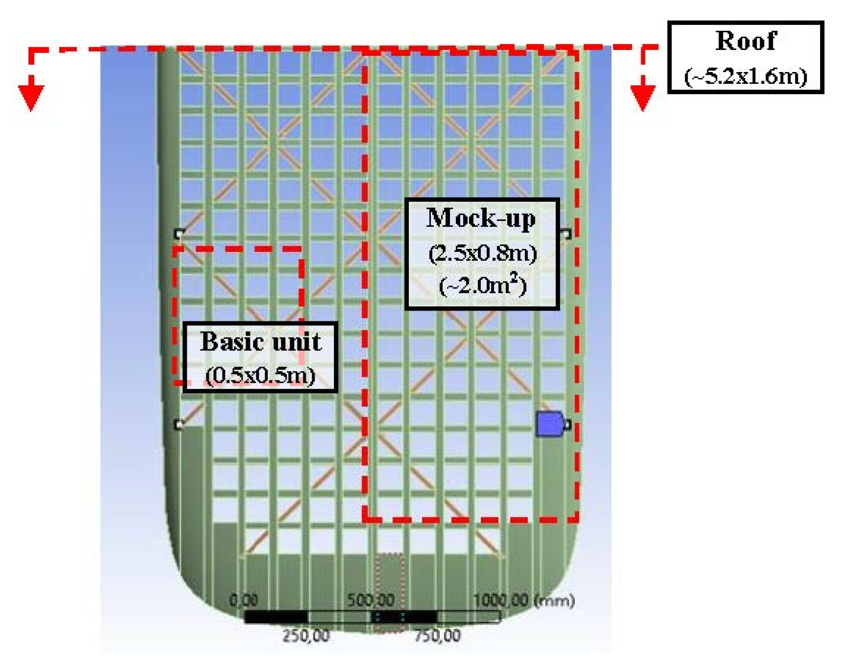
Decoupling the effects related to the geometric characteristics of the basic shapes (i.e., rectangle, triangle, etc.) from those related to their recurrence and rearrangement. It was obtained repeating the optimization procedure acting on different levels. Specifically, in
Figure 3 these different scales of analysis are displayed, showing the basic unit (500 × 500 m), used for geometrical optimization of shapes (
Figure 2), and the mock-up (2500 × 800 mm), used for grid optimization, experiments and model validation. It should be noted that the figure shows half (front) section of the vehicle roof (with ~5200 × 1.600 mm as overall dimension);
- -
Limiting the (full) parametric (and automated) analysis to an optimization only based on the structural outputs as first; the most promising solutions from this topologic optimization are then (individually) verified in terms of impacts on the performance outputs.
2.5. Design and Simulation Tools
3D CAD modelling was performed in SolidWorks (by Dassault Systèmes, Vélizy-Villacoublay, France). Ansys Workbench ver. 18.1 platform (by ANSYS, Inc., Canonsburg, Pennsylvania, USA) was used for structural analysis of composites (by an ACP toolkit) and for design optimization (Design Exploration) by the direct optimization features and the screening and response surface method.
Specifically, in 3D modelling solid parts were suppressed with the scope to manage 3D surfaces. Discretization was done by shell elements (FE), quadrangular of quadratic order with 8 knots, preferred for precision. After mesh convergence tests, the maximum size for FE was set at 3 mm (in the case of basic units), employing 12,000–18,000 FE for meshing the different configurations.
In accordance with reality, the thickness of sandwiches was made variable along the section by creating cut-off selection rules in ACP and assigning them to the PVC core. The same technique was adopted to manage edges and intersections. A visual example of effects of expedients used for the correct discretisation of composite structures is reported in
Figure 4 in the case of rectangular grid. The 500 × 500 mm base section, consisting of 4 × 4 squares (representing the solar cell frames) are shown highlighting differences in thickness and the final mesh with implemented these changes.
The so-called single-layered shell method [
33], instead of many others (e.g., stacked shell [
34]), was chosen and implemented for discretizing the layout. This simplification quite common in analyzing composites in the case of large and complex structures, permits to quickly investigate the main phenomena at the level of macroscale. With a proper conversion in properties, it reduces a multilayered laminate to an equivalent single layer laminate and use shell elements all along the surface with integration points (IP) throughout the thickness [
33]. Specifically, in the case an IP was set per each of the seven layers: no additional IP was used to investigate the six interfaces between layers. In such a way it was possible to drastically limit the number of FE speeding up the simulation focusing the attention on in-plane phenomena [
33,
34,
35].
However, this methodological limit has no practical effect on the present study since the roof has no global structural functions [
35]. The vehicle was designed around a lower monocoque and an upper structure (
Figure 1b). A rigid frame on the composite structure guarantees the fixing and solidity of the roof which, practically, in addition to its own weight, must only support the solar cells (~ 1.2–1.5 kg/m
2).
From the Ansys internal library, material models labelled as “Epoxy Carbon UD (230 GPa) Prepreg”, “Epoxy Carbon Woven (230 GPa) Prepreg” and “PVC Foam (80 kg m
−3)” were chosen for, T1000, T800 and PVC respectively, but default properties were changed in accordance to
Table 1. ACP toolkit permitted to build exact layouts as shown with
Table 2. In the grid configuration, in order to correctly orient the fibers according to the direction of the single beam, it was necessary to divide the grid in section subgrouping beams characterized by a same orientation in the fibers.
2.6. Simulation Procedures
Three different simulations were carried out on each configuration under investigation.
2.6.1. Resonance Frequency
The first simulation was a modal analysis and concerned the resonance frequency. It was carried out in free-free conditions: no constraints or forcing were set. The first six modes are rigid modes, corresponding to the structure’s six degrees of freedom. Therefore, the seventh mode and frequency correspond to the first modal shape of interest (
Figure 5a).
2.6.2. Flexural Stiffness
The second simulation was a static analysis and concerned the flexural stiffness. Load conditions were set equivalent to a simply supported beam with distributed load. Constraints were assigned to two opposite external sides of the beam and a force equal to 1 N (to simplify calculations) to upper face. The model was simplified as a beam considering the complete roof structure, consisting of various repetitions of it, has a prevalent dimension over the others. The required output is the flexural displacement (total deformation). Flexural stiffness can be calculated by dividing the force by the maximum displacement (
Figure 5b).
2.6.3. Torsional Stiffness
The third simulation was a static analysis, as the previous one, but concerned torsional stiffness. As a system, it was considered a cantilever beam with a pure twisting moment applied at the end. A fixed support was therefore assigned to one side and a torque of 1 N·mm to the opposite side. Torsional stiffness can be calculated as:
where
T is the twisting moment,
θ is the rotation,
z1 and
z2 are the vertical displacements at the two ends and
b is the length of the beam. The rotation
θ was determined, in the case, directly using the Flexible Rotation Probe function instead of the analytical formula after verified the results by the two methods were similar (
Figure 5c).
3. Results and Discussion
3.1. Shape Topological Optimisation
In
Table 5 a first comparison between geometries at the level of basic unit is reported in terms of performance index (IC) respect to their main dimensional characteristics (sizes).
Specifically, in the case of laminates dimensions refers to the hole sizes as width (W), height (H) and fillet radius (r) for a rounded rectangle or 1st and 2nd (A, B) axes for ellipsis.
In the case of the grids, the dimensions refer to the width of beams that make up the structure: an upper orthogonal (0–90°) grid, reinforced by a lower diagonal (±45°) one. A value of 30mm in width for the upper grid is fixed considering the need to sustain the singular solar cell. Both for laminates and grids 5.2 mm of thickness is fixed since the predetermined composite layout (
Table 2).
In terms of results, it should be noted that, together with the torsional and flexural stiffness, the first (lowest) natural frequency is also reported in the table. This value represents an indication of how sensitive the structure is to the effects of vibrations. The maximum displacement respect to the first natural frequency should be also considered representing the effect of vibrations in terms of intensity (not sensibility).
By comparing the values of the performance index (IC), it is immediately evident that the best configurations are, in general, grid configurations (as
Figure 2c,d) reinforced by several crosses (IC ≥ 0.48) and, specifically, a quadridirectional configuration (IC = 0.79). Despite this, the option of manufacturing a laminate in a single body and then lightening it through holes could be taken into consideration provided the choice of rectangular (IC = 0.61), almost squared (~95 mm vs. 93 mm), and rather large holes (~8800 mm
2) with rounded borders (~24mm). In making these considerations, it should be also remembered that all these configurations are obtained keeping the same weight (w = 0.264 ± 0.01 kg) as target and, consequently, the same amount of material.
Outcomes from
Table 5 also take into count, as a preliminary optimization (improved below), the way an upper orthogonal grid (orthogrid) can be reinforced by lower transversal crosses leading to double grid configurations. The most interesting options, between many others under consideration, are displayed in
Table 6 where at the investigation level of the basic unit, the impact of a crescent number of crosses is analyzed. The same table also exhibits the effect of changes in cross angles.
Results, as said, assumed that:
- -
All beams in each specific grid have the same dimensions (i.e., width and thickness);
- -
These dimensions can vary (in general) between the upper and lower grids;
- -
The thickness, however, is fixed by the specific composite layout;
- -
The width of beams in the upper grid is fixed (with the scope to permit to sustain the solar cells);
- -
The width of beams in the lower grid is related to their number (since a constant weight).
For each configuration, the table reports stiffness in the cases of application of (flexural or torsional) loads along X or Y axes. Differences are evident related the geometrical anisotropies of grids respect to these changes in the axes.
3.2. Grid Topological Optimisation
In
Table 7, a second comparison between configurations is reported. It also deals with the best solutions detected in terms of geometry and shapes at the level of basic units (
Table 5) but extends results on the mock-up case. In particular, the laminate with rectangular holes where compared with quadridirectional grids in different configurations. Having demonstrated a certain appropriateness (measured through IC) for a specific configuration at the level of basic unit does not necessarily mean, in fact, that this rank remains the same on the mock-up. Such a fact immediately emerges from the table making clear that the laminate with rectangular holes (IC = 0.25) is no longer convenient.
Having also demonstrated the convenience of using, as general design concept, a grid structure where an upper orthogonal grid (on which the solar panels are laid) are reinforced by a series of diagonal crosses, a different topological optimization study was carried out with respect to the definition of the (lower) grid in terms of number of elements and their arrangement.
Without entering in unnecessary details,
Table 8 exhibits the impact of diagonal crosses at the level of mock-up, both as number, distribution and crosses angles.
The beam width in upper grids remains 30 mm (to conveniently host the solar cells), but changes affect the lower ones (from 14 to 50 mm) according to the condition of weight conservation. Spacing parameter (in
Table 8 and
Table A2) provides information on the distance between beams on the lower grid: reducing the distance increases the number of beams (and crosses as reinforce) but, on the other side, as said, reduce their width saving the total weight. Finally, unlike the first analyses on the geometric parameters, where an automatic change for (almost) all the parameters was possible, in these further investigation configurations often involve the development of specific CAD models. Thus, several actions were done manually.
3.3. Multi-Objective Optimization Results at a Glace
In line with results from similar investigations (as [
36]), it is clear how the grid structures are preferable to perforated panels. It is also evident that a grid with a denser mesh is better than those of sparse one with an equivalent weight. However, although the comparisons give unambiguous indications when only mechanical properties are considered, additional criteria should be included.
In fact, the optimized option as here detected, i.e., quadridirectional grid with crosses every 250 mm, could present (compared to less dense grids) additional challenges in its applicability such as:
- -
Minor free surface for heat transfer, not permitting an efficient the solar cells cooling;
- -
Greater complexity in fabrication related to a larger number of basic elements (beams).
These aspects were not including in the optimization since the beginning and are not considered.
A preliminary estimation of the free surface carried out by Ansys with respect to two borderline grids showed a quite low variability (<10%): using a denser grid does not significantly affect the panels cooling. It also depends to the fact that, denser grids are necessarily made by tighter beams (since the precondition of equivalent weight).
Regarding the composite roof construction, with an area of approx. 8.0 m2, its manufacturing can represent a laborious task. A larger number of beams and crosses, to be made and glued, would be preferable only when mechanical properties were significantly better: it is not the present case.
Table 9 reports an update in design solutions evaluation, taking into count of additional parameters and objectives of optimization. In particular, the maximum displacement when the lowest natural frequency occurs is included: those parameters have to consider in combination for better analyze the dynamic behavior of the structure. Furthermore, the table also introduces parameters, not strictly related to mechanical properties, as the area available for heat transfer and an indicator of producibility. While the exposed area may be directly detected by Ansys functionalities, an empirical index had to be defined for estimating the producibility, it was done in accordance with information from manufacturer, making its value proportional to the number of operations necessary to build composite structures.
As a synthesis, a quadridirectional grid with crosses every 500 mm was adopted. In accordance with previous results, in fact, this structure exhibited good mechanical properties, better than both perforated sandwich panels (especially regarding the resonance frequency [
37]), but also compared to an orthogonal grid, thanks to the presence of reinforcing beams in the diagonal directions [
38]. However, its medium sparse grid does not entail the construction problems that can occur during production in the case of denser grids.
Finally, since it was noticed that a slight increase in the mass of the angular grid provided positive benefits to the quadridirectional grids, it was also preliminary checked the effect of minor changes in the constraint of the minimum width for the orthogonal beams (=30 mm).
The basic unit of 500 mm sides was examined, performing a further optimization in Ansys by varying the width of the orthogonal beams between 25 mm and 30 mm and diagonal beams between 30 mm and 50 mm. Since the condition of equal total weight, an increase in the mass of one grid, orthogonal or diagonal, decreases the other. In general terms, the best situation is present when widths of both grids are quite similar. A specific optimization can be obtained when the choice of the solar cells, defined the lower value of width for elements in the upper grid.
3.4. Validation
A modal analysis was used for validating the FE model by experiments.
The mesh consisted of 56163 shell elements and allowed to identify the first 20 modes of the structure (of which, six are rigid modes). Deformations along main directions and Cartesian axes were also evaluated. On the other side, a modal test was also carried out both with accelerometers (as in [
39,
40,
41]) and Bragg grating fibers (FGB) sensor (as done in [
42]).
Figure 6 and
Table 10 summarize this comparison for a range lower than 100 Hz, equivalent to the five lowest natural frequencies. A good accuracy is clear with a 7.3% average deviation between predictions and experiments. Besides, a constant underestimation is also evident which suggests a refining in the FE model discretization.
3.5. Results Implementation
The same design approach was used to finalize the roof design. The 3D geometry of the roof was filled by structural modules with design parameters based on the previous optimization. Specifically, a quadridirectional grid with a medium density of beam element was used as valid compromise between the different targets. It was characterized by an orthogonal grid on the top and a lower diagonal grid on the bottom with, respectively, 300 mm and 200 mm widths. This design pattern was replicated along the roof dimension and shape, partitioned in front and back sections (
Table 11).
The dynamic behavior of these parts was examined by a further modal analysis considering unloaded bodies (as previously) but constrains as in real case. First frequencies were 21 and 12 Hz with total displacements of 42 and 69 mm for, respectively, front and back sections (
Figure 7)
Then, the composite structure was manufactured using manual layout and autoclave molding and hot gluing with two-component for part assembly. The solar cells, E60 bin Me1 by Sunpower, were directly laminated on the panel with ethylene vinyl acetate (EVA) films. Flexible layers on both surfaces (front and back) for a total of five layers (including 2 EVAs), for a 1.5 mm of overall thickness, were overlapped and cured in autoclave. In particular, solar cells were positioned with the scope to maximize the energy yield of vehicle-integrated photovoltaics (VIPV) [
43].
Lastly, the solar roof was installed and finalized with other vehicle components.
Figure 8 shows several imagines from the solar vehicle at the end of the present investigation. Functional tests were performed running over 800km on roads open to traffic. No complications emerged related during this first trial in terms of structural design of the roof which appeared stable and functional.
3.6. Further Considerations and Novelty
Following the use of a multi-objective optimization in this design action, several general considerations can be introduced. As first, it is essential to note how the outcomes strongly depends on the weight assigned to the objectives: even minor changes in their values can lead to very different design indications. Thus, it would be relevant to find criteria for an empirical definition of these parameters. By an analysis simply based on mechanical aspects (e.g., Eigen value optimization), it is quite hard, in fact, to detect very uncommon design solutions or issues respect what already available as technical know-how such as, for instance, the superiority of reticular structures. Moreover, when further objectives are introduced in optimization, but always of the same type (such as, e.g., the minimization of an area keeping weight or stiffness unchanged), results do not change. Reticular structures seem the best solutions, especially when characterized by a certain geometrical complexity. However, as soon as a goal not strictly related to the ‘structural engineering’ is introduced, optimal solutions start to evolve along unpredicted directions.
For instance, a sandwich panel, made in composite by a single stratification that also considers the lighting holes, can be much simpler in terms of producibility respect to a composite grid. Then, when an additional parameter related to the producibility is introduced in the evaluation, moving the analysis from a ‘topologic’ to ‘multi-object’ approach, this perforated panel significantly increases its ranking respect to grid solutions. Similarly, lower density grids start to be more attractive.
However, without the possibility of objectively validating the weight of each objective, a deeper level of analysis risks to be inconsistent respect to the real applicability of results, which represents the essence and novelty of the present investigation. In fact, this study was intended to be a first attempt in the contest of solar vehicles to move from redesign action based, as tradition, on a trial and error approach toward a multi-step and -objective one method. To the knowledge of the authors, in fact, no other design studies are available dealing with the multi-objective optimization in an automotive context that involve fiber-reinforced sandwich structures of such large size and geometrical complexity.
4. Conclusions
The application of a multi-objective approach to the complete design process of an actual composite structure was shown. Specifically, a photovoltaic roof for solar vehicles was designed following a multi-objective approach in the way to balance divergence structural criteria, as static stiffness and dynamic response, with additional functional targets. Heat transmission and energy efficiency were also considered.
As first, several alternative shapes (circles, squares, triangles) were compared as pattern. Then, for selected shapes, the optimization was carried out respect to their main parameters (e.g., lengths, angles) searching the optimal points inside Ansys FEA software. A performance index was properly defined to represent the best compromise and a large number of configurations were compared. This index combined aspects as flexural stiffness, torsional stiffness, resonance frequency and heat transfer surface by the definition of weight parameters for each target. To simplify the study, a multistage approach was preferred. As first, a 500 × 500 mm section, equivalent to 4 × 4 solar cells, was adopted as base for an initial comparison between fundamental shapes (e.g., triangle, rectangle, ellipses). A total of 49 designs, each one characterized by a specific combination of shape and geometrical parameters (as widths, angles) were considered and compared, limiting the input for the next stage to few (4) optimal options. Hence, this base unit was used as design modulus to build a larger geometry (2500 × 800 mm) able to better predict and compare the structural behavior in a case study closer to reality. This second step of optimization, performed by 51 designs, permitted to recognize the quadridirectional grid as the best solution and to define proper combinations of geometrical parameters.
The FE model was validated comparing results from simulations and experiment respect to a modal analysis: a good accuracy with a 7% deviation in predicting the lowest natural frequencies was detected. The structure design, as here optimized thanks to a quadridirectional grid, was applied to the case of the real roof, characterized by larger dimensions (~5200 × 1.600 mm) and a double curvature geometry. A FE modal analysis of the roof, done in accordance with real loads and constrains, was carried out to determine the lower frequencies (higher than 12 Hz) and modes.
The composite structure was produced using autoclave technology; solar cells were also direct laminated on it. The solar panels, with an overall thickness lower than 5.2 mm, were installed on the vehicle and functionally tested on the road with valid results.


