Article

Method for Volume of Irregular Shape Pellets Estimation Using 2D Imaging Measurement

1
Department of Electronics Engineering, Kaunas University of Technology, Studentu St.50-438, LT-51368 Kaunas, Lithuania
2
Faculty of Technical Sciences Kosovska Mitrovica, University of Pristina in Kosovska Mitrovica, Kneza Milosa St. 7, RS-38220 Kosovska Mitrovica, Serbia
3
Department of Radio Electronics, Brno University of Technology, Technicka 3082/12, 616 00 Brno, Czech Republic
4
Department of Telecommunications, Brno University of Technology, Technicka 3082/12, 616 00 Brno, Czech Republic
*
Author to whom correspondence should be addressed.
Appl. Sci. 2020, 10(8), 2650; https://doi.org/10.3390/app10082650
Submission received: 19 March 2020 / Revised: 6 April 2020 / Accepted: 9 April 2020 / Published: 11 April 2020
(This article belongs to the Special Issue Applications of Computer Vision in Automation and Robotics)

Abstract

:
Growing population and decreasing amount of cultivated land conditions the increase of fertilizer demand. With the advancements of computerized equipment, more complex methods can be used for solving complex mathematical problems. In the fertilizer industry, the granulometric composition of products matters as much as the quality of production of chemical composition products. The shape and size of pellets determines their distribution over cultivated land areas. The effective distance of field spreading is directly related to the size and shape parameters of a pellet. Therefore, the monitoring of production in production lines is essential. The standard direct methods of the monitoring and control of granulometric composition requires too much time and human resources. These factors can be eliminated by using imaging measuring methods that have a variety of benefits, but require additional research in order to assure and determine the compliance of real-time results with results of the control equipment. One of the fastest, most flexible and largest amount of data providing methods is the processing and analysis of digital images. However, then we face the issue of the suitability of 2D images to be used for the evaluation of granulometric compositions, where processing of digital images provides only two dimensions of a pellet: length and width. This study proposes a method of evaluating an irregular pellet. After experimental research we determined < 2% of discrepancy when compared to the real volume of a pellet.

1. Introduction

The rapid application of modern technologies is evident in many various industries. The increasing performance of computer equipment and the wider realization of various theoretical mathematical calculations expands the possibilities of applications of equipment. The largest volumes of production are conditioned by application of cutting edge technical and scientific solutions in various fields of industry. The chemistry industry is no exception. The increasing demand of food supplies and scarcity of cultivated land is a reason for the wider application of fertilizers. Rational fertilization of cultivated land and optimal distribution across the surface of soil or insertion into soil results in better harvests. Therefore, there are specific requirements for the size and shape of fertilizer pellets. However, it is a huge task for manufacturers to assure the quality of fertilizers. As the fertilizer pellets are quite small (2–4 mm in diameter), it is difficult to evaluate their quality by using direct methods of measuring.
With increasing productivity, the best tools for quality assurance are indirect methods of measuring that allow real-time evaluation of the quality of pellets [1,2,3,4,5,6,7,8,9,10,11,12,13]. The technique of processing digital images provides results that are very similar to the results of control equipment based on direct measurements [14,15,16,17,18,19]. A variety of image enhancement methods assure reliability of results [20]. A high frequency of discretization of production monitoring allows for a quick reaction to any production process deviations that manifest in changes of production parameters. Applied numerical intellect solutions simplify the preparation of equipment for work [21,22].
One of the most important qualitative parameters used for the evaluation of pellets is their distribution according to size [23]. However, other parameters are not less important, such as: distribution according to roundness, elongation, compactness, uniformity index of pellets and so on [24]. According to the international standards of sampling and the evaluation of samples [25,26,27], the manufacturer strictly defines qualitative parameters related to other physical parameters. Round pellets and pellets that are categorized by nondispersive size distribution are more likely to be more evenly distributed during fertilization using an automatic spreader [28,29].
Optimal spreading conditions are achieved with higher bulk density, because it creates further throwing distance of the pellets. Various fertilization quality assessment systems are installed depending on the type of spreader used [30]. However, it must be combined with optimal distribution interval of pellets—ideally, distribution interval deviates by ±0.8 mm (width) from the average [31]. Additionally, the more the shape of the pellet is similar to an ideal circle, the longer the distance of its flight, because of its aerodynamic properties. Hardness of the pellet prevents the disks of the pellet spreader from breaking it apart [32].
One of the relevant problems related to using indirect measuring methods is the matching of the results to those from using direct methods. It is especially difficult to evaluate the pellets of irregular shape. According to the literature analysis, many various methods are used for scanning of pellets as well as recalculation of results. The main purpose of this article is to propose a fast method for evaluating the quality parameters of fertilizer pellets, which would ensure continuous quality control. This can only be achieved through indirect measurements. Digital image analysis allows for versatile and fast output analysis. However, there are problems with the evaluation of irregularly shaped pellets in two-dimensional images. This increases the discrepancy between the actual results and the results of the indirect measurement. In this work, the proposed method of evaluation of fertilizer pellets of irregular shape is via processing and analysis of digital images. The obtained results of the proposed measurement method can be applied in the fertilizer production lines for continuous monitoring of production quality. In Section 2 (Materials and Methods), methods of pellet volume evaluation, when their scanning is carried out using imaging measurement techniques, are analyzed. In the second part of the work (Results, Subsection—Evaluation of pellet’s shape) experimental tests are carried out in order to evaluate the production, which is the studied product. Shape characteristics of the pellets (studied product) and related problems are determined. Further on, the applied method of pellet volume calculation, where pellets are divided into layers of least possible height, is analyzed (Subsection—Division of pellet volume into layers). General volume is calculated by integrating the layers of pellet. Based on the received results, an improved method of the calculation of pellet volume was proposed, namely, evaluation of layer using geometric form—ellipse (Subsection—Approximation of pellet cross-section layers using ellipse). In Section 4 (Discussion) information about the improved method of pellet volume evaluation is presented. Meanwhile, conclusions are given in the final section.

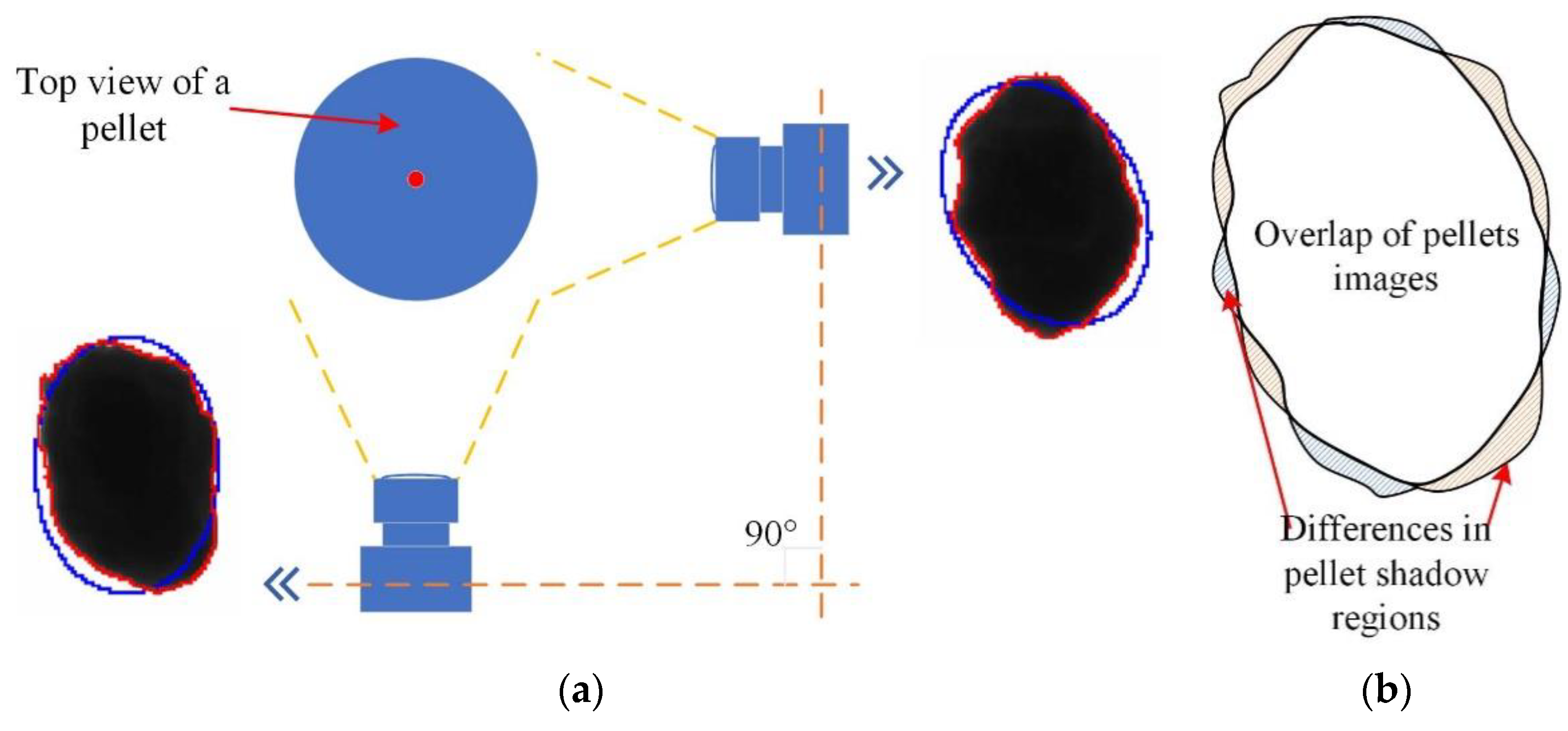
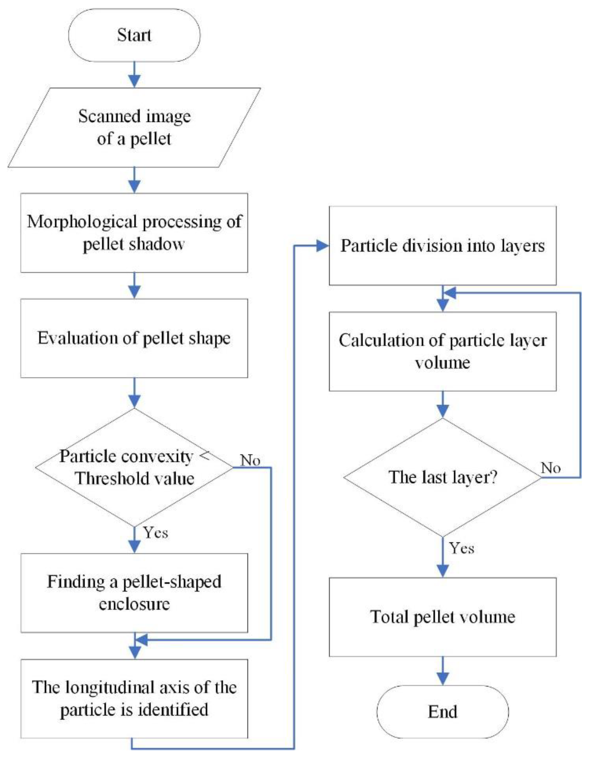
2. Materials and Methods

The amount of data received from analysis of the digital image processing is limited for determining the distribution of pellets. Depending on the material being analyzed, pellets can be of irregular shapes, and any approximation of such pellets may largely differ from their real surface.
Two-dimensional (2D) image information always provides only two parameters of pellet size: length and width. Therefore, the precision of evaluation of its volume depends on the level of matching between the approximation model and real surface of a pellet. The contours of pellets are usually approximated using geometric forms that are most widely used in calculations, such as circles, ellipses or best fit rectangle (smallest area limited by rectangle that can define the shape of pellet) [33]. These models are used for defining the contour of a pellet, as well as drawing the largest possible shape (limited by the perimeter of a pellet) inside of a contour of a pellet (Figure 1).
Such forms of approximation are characterized by limitedness, as in the case of an irregular pellet shape the area limited by its contour can be up to two times larger than the real area of the pellet (Figure 2a). This approximation form is the reason for discrepancy between measured volume and real measurement results. To account for such discrepancies, a model of the area (matching real area of a pellet) limited by the regular geometric shape is used (Figure 2b).
Such methods of pellet shape evaluation are used with silhouette contour approximation using ellipses [34], because this geometric shape allows for better evaluation of roundness of the pellet, when compared to a circle shape. The ellipse contour provides information about longitudinal and transverse dimensions. This method of measurement is similar to the sieve method. In many laboratories, sets of sieves are used as a control equipment of examination. In this case, when distribution of pellets must be determined, the main parameter is the width of the ellipse that limits the area of the pellet. The width of the ellipse is the same as the diameter of the holes of the sieve. Matching between the holes of a sieve and the approximated form is presented in Figure 3.
The sieve method used for the measuring of pellets is not a rational choice for evaluation of parameters of their shape. This is related to the working principle of sieves, which only allows for evaluation of two out of three dimensions of pellet, as the pellet falls through sieve when two of its three transverse dimensions are smaller than the diameter of holes of the sieves. In such a case, a third diameter as well as shape of the pellet is left unmeasured. The precision of measuring is also limited by the number of sieves with holes of different diameters. The technique of processing digital images expands the measuring possibilities, while more precise mathematical models used for pellet approximation conditions the improvement of precision and reliability. The correction of the final distribution of the pellets is used as an alternative, e.g., an evaluation carried out only with pellets which are shaped very similarly to the regular shape of a pellet [35].
During the indirect measuring, based on digital image processing, various geometric shapes are used for the approximation of pellets, according to the area limited by their silhouette. One of most common geometric shapes is volume limited by ellipsoid Equation (1) (according to Figure 1e) [36]:
V = 4 3 π r 1 r 2 d 2 2 ,
where r1, r2—radius of ellipsoid; d2—length of ellipsoid.
The analyzed scan of the pellet image is two dimensional, therefore in calculation we additionally use the width of the ellipsoid, i.e., instead of one radius of the ellipsoid, which is equal to the depth of image, the other radius is used in Equation (2):
V = 4 3 π r 2 r 2 d 2 2 = 4 3 π r 2 2 d 2 2 ,
where r2—radius of ellipsoid; d2—length of ellipsoid (ellipsoid scheme in Figure 4).
When pellets are analyzed in terms of volume distribution using Equation (2), each pellet is evaluated as a shape of the ideal ellipse. Such an evaluation will be correct only in specific cases, when the product is characterized by a high index of roundness and smoothness of surfaces. These parameters are determined by chemical composition of a pellet. It determines their fragility and adhesion of mixture. Therefore, when working with irregularly shaped pellets, the method of ellipsoid volume evaluation causes a discrepancy between the results and the real volume of such pellet.

3. Results

The reliability of the evaluation of pellet volume depends on the shape of a pellet. An evenly shaped, not fractured pellet that is resistant to mechanical impact can be evaluated precisely, using approximation of a circle shape. However, in reality we see many irregularly shaped pellets. Therefore, their evaluation using 2D imaging decreases the reliability of the method. Discrepancy is introduced with irregularities of the pellet’s surface. For developing a method of the evaluation of volume of irregularly shaped pellets, primary analysis of production is necessary, because the shape of surface irregularities must be evaluated.

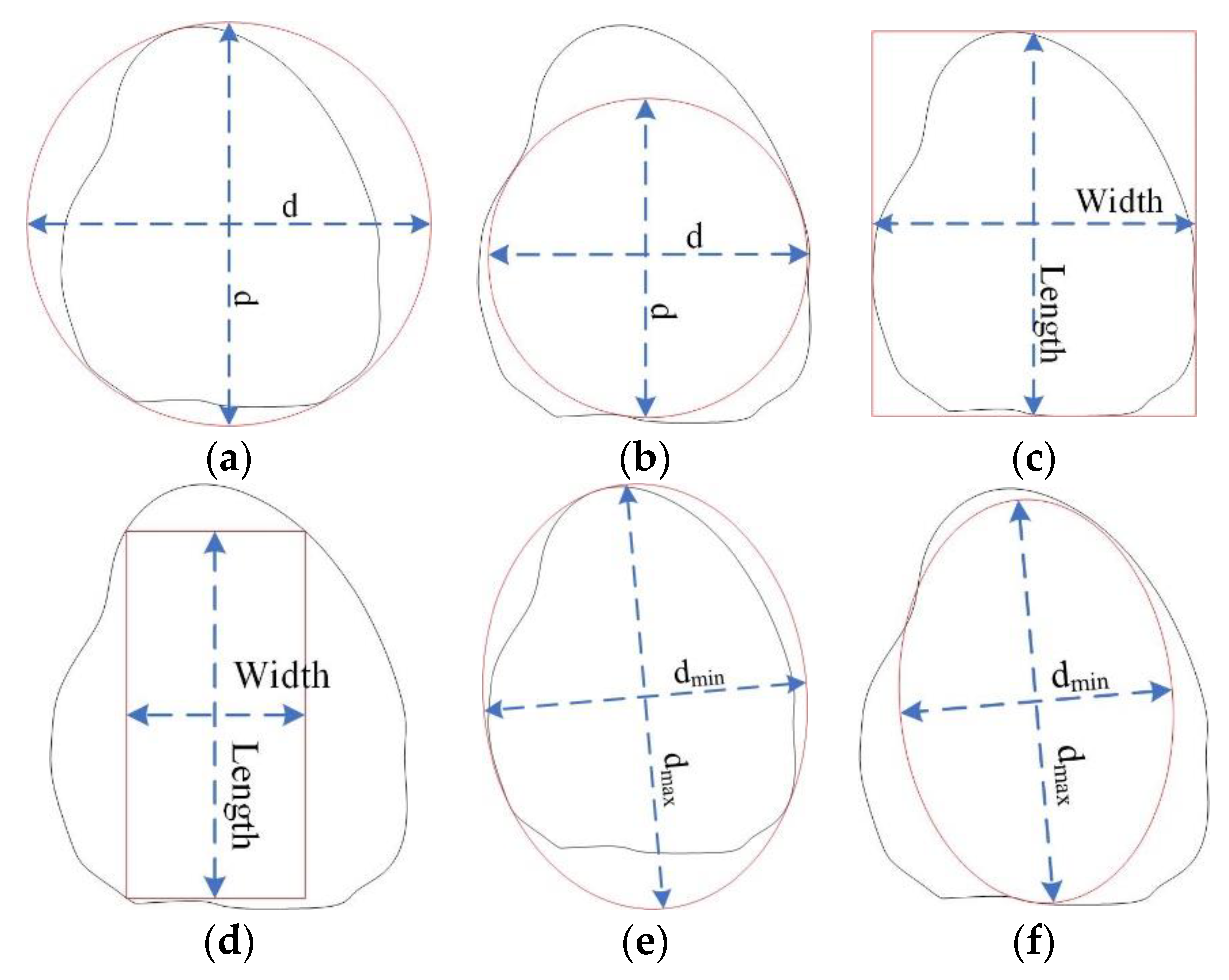
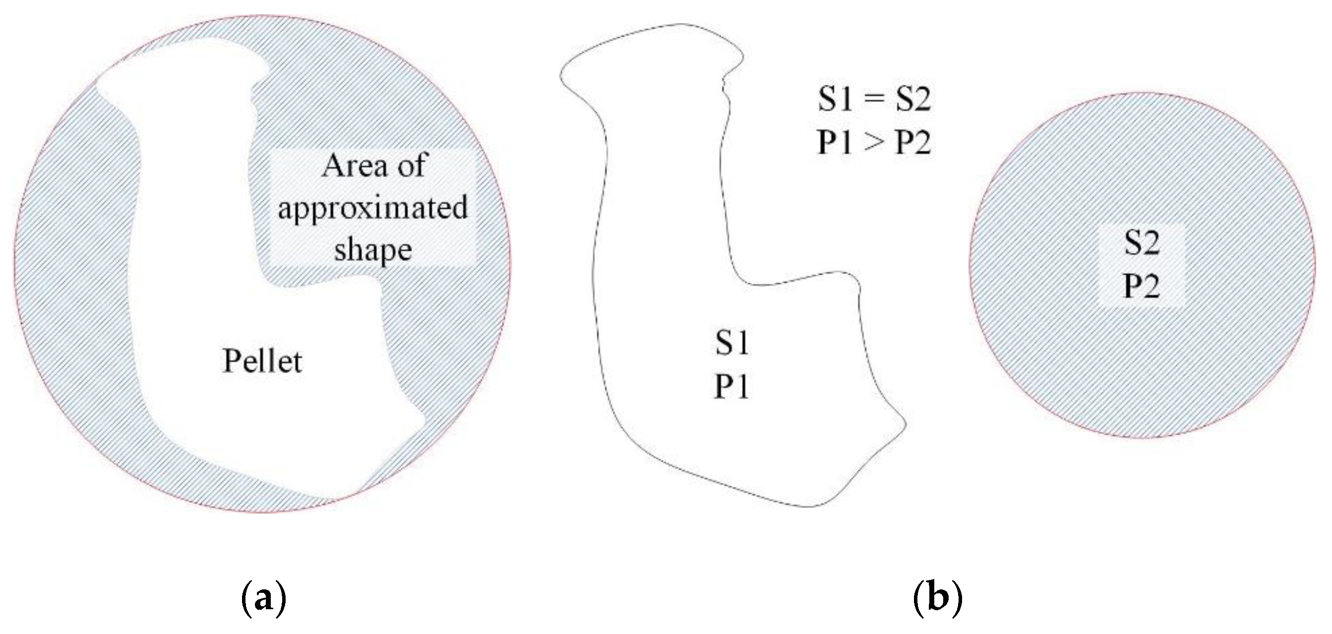
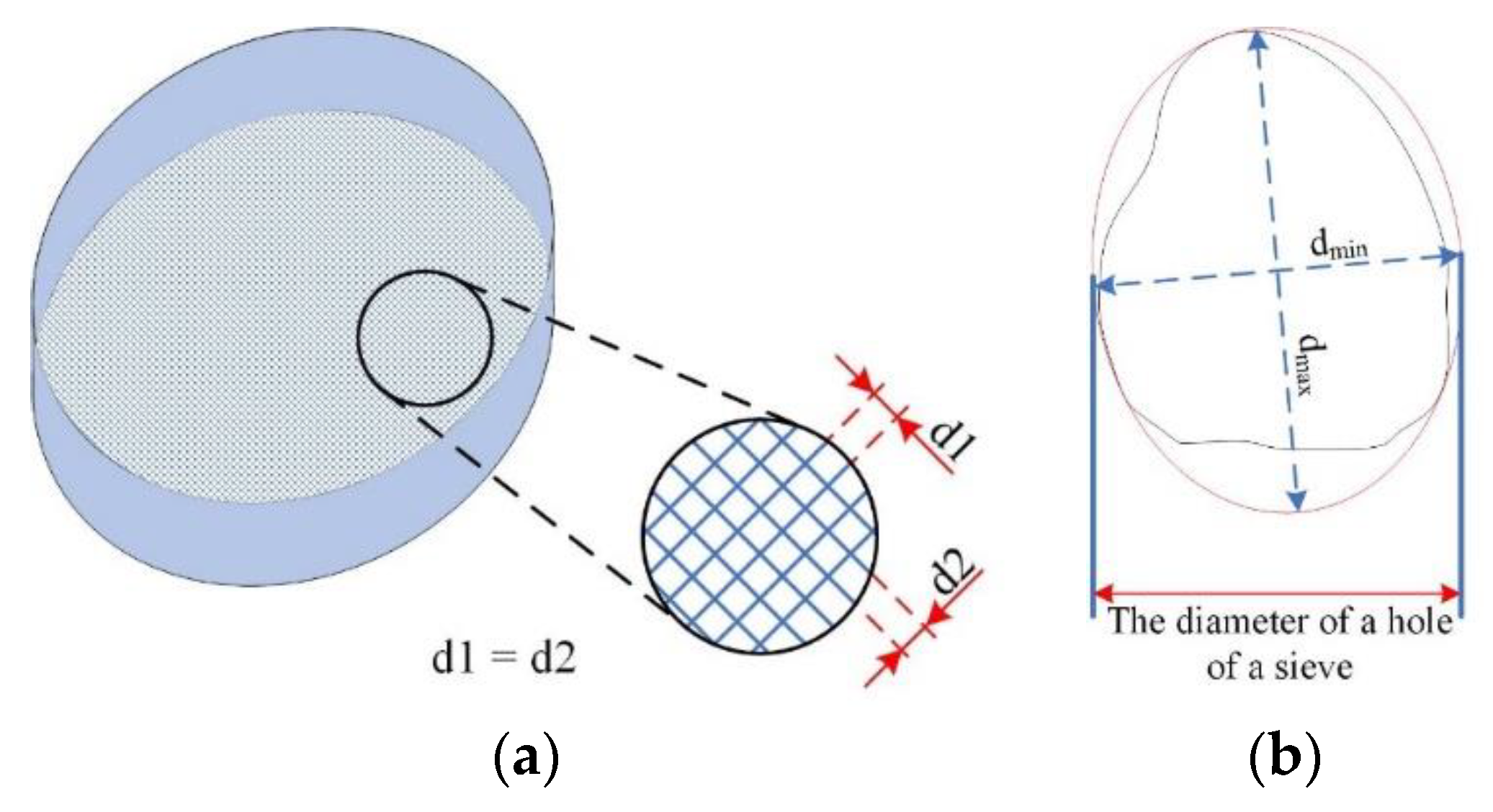
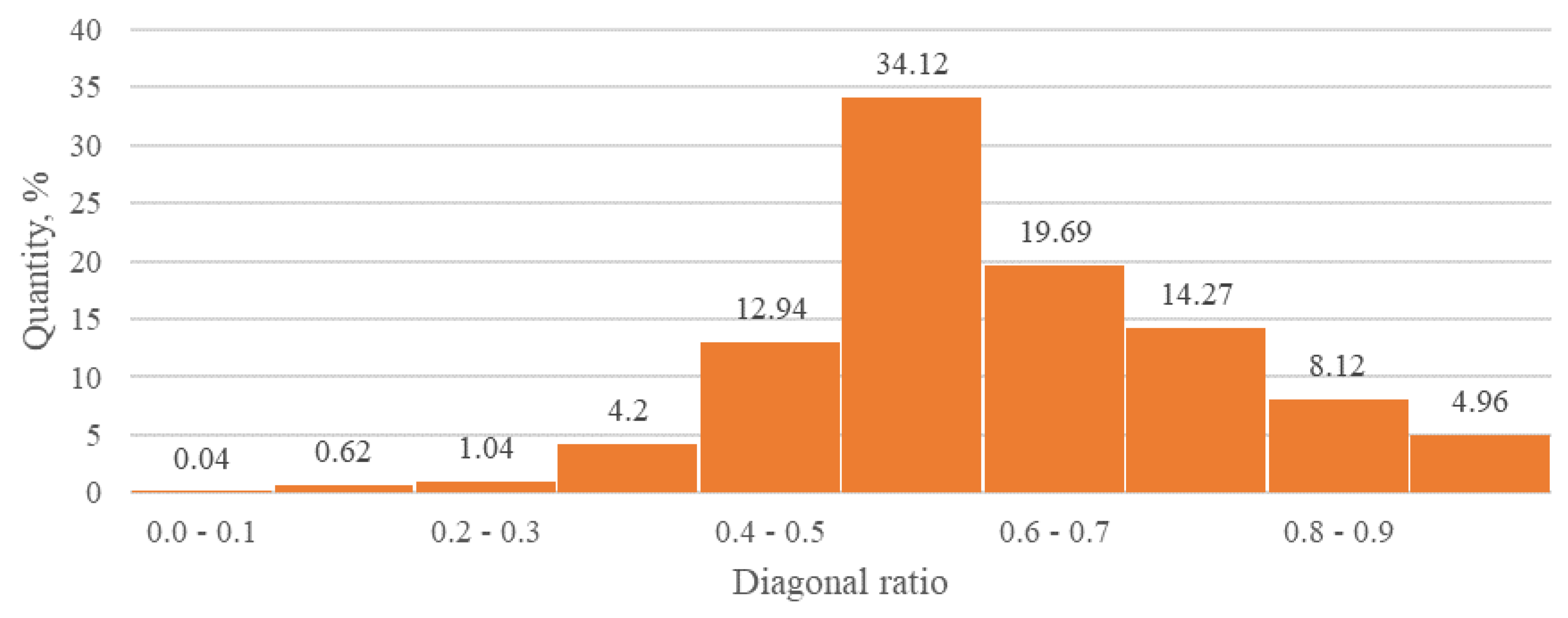
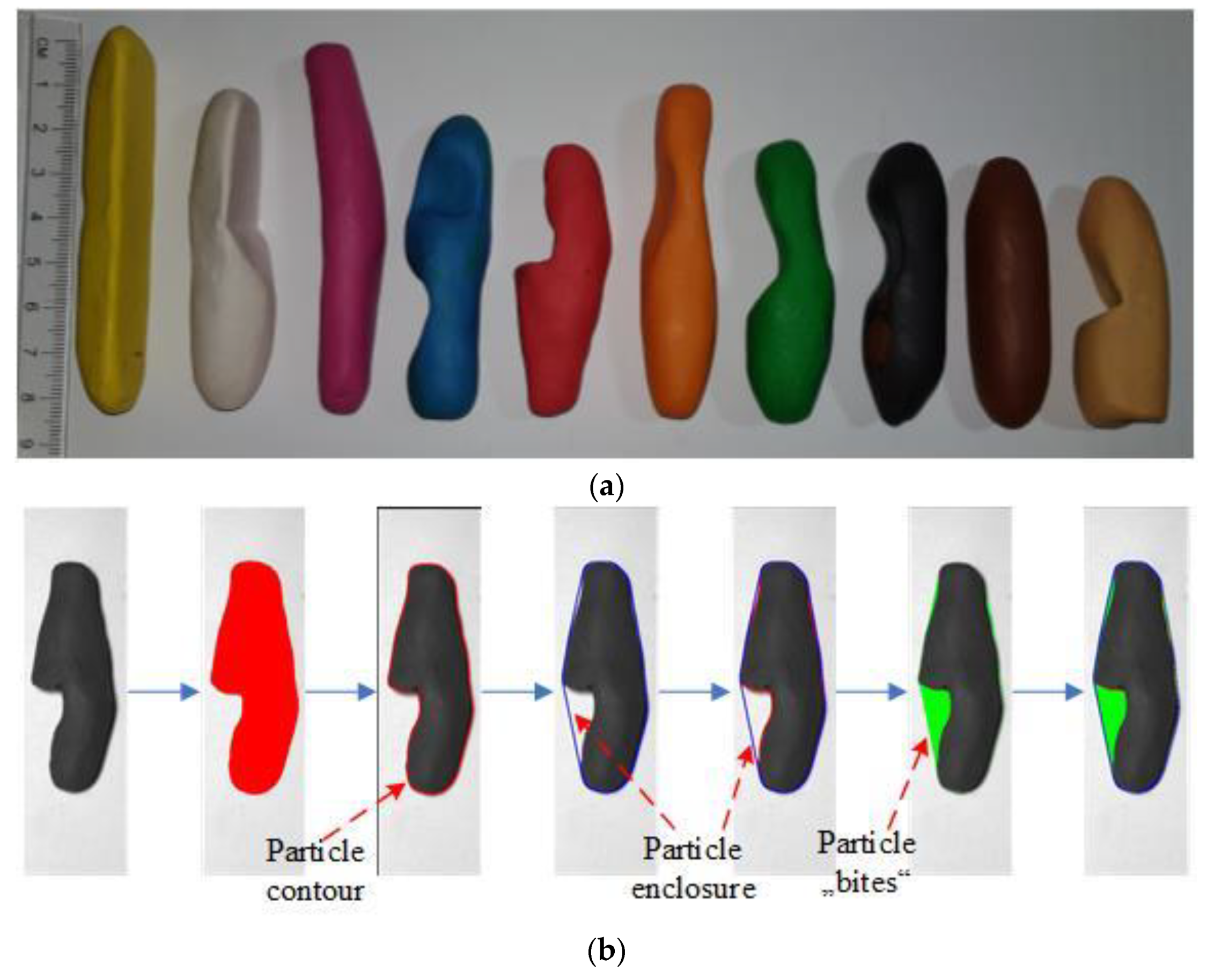
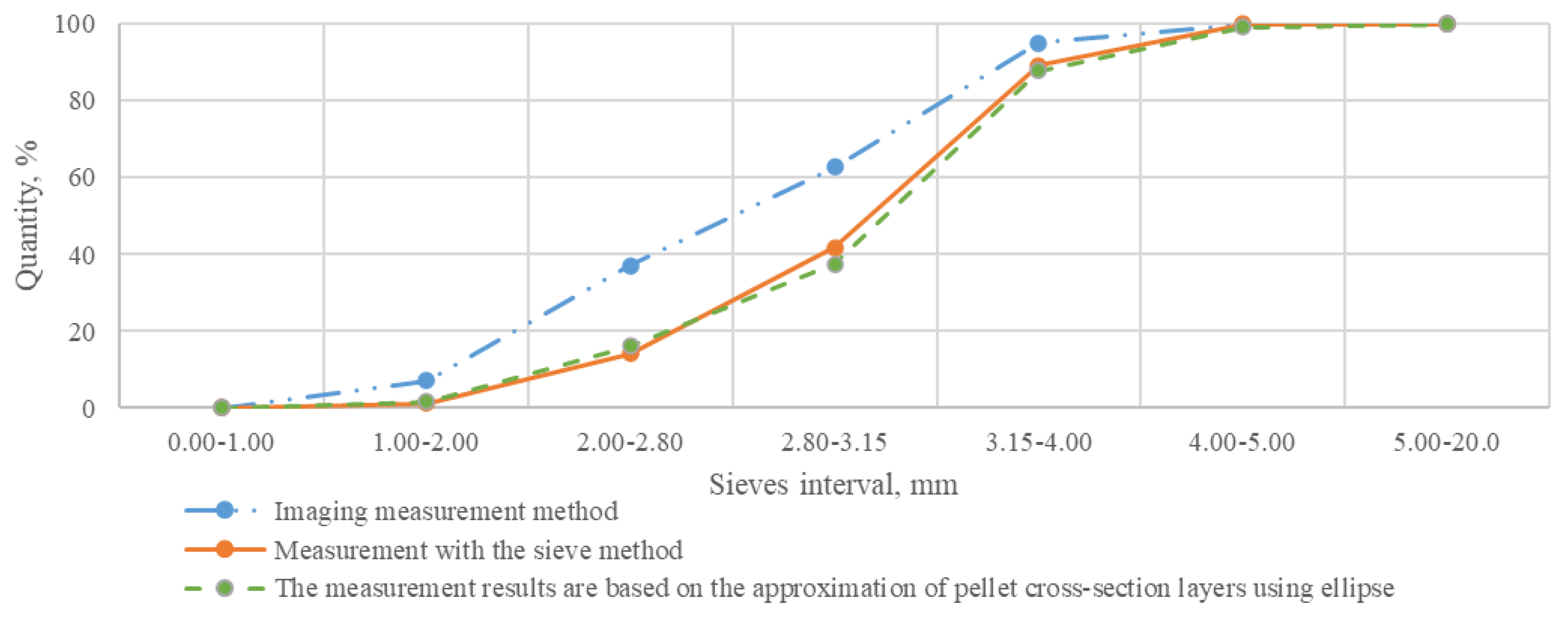
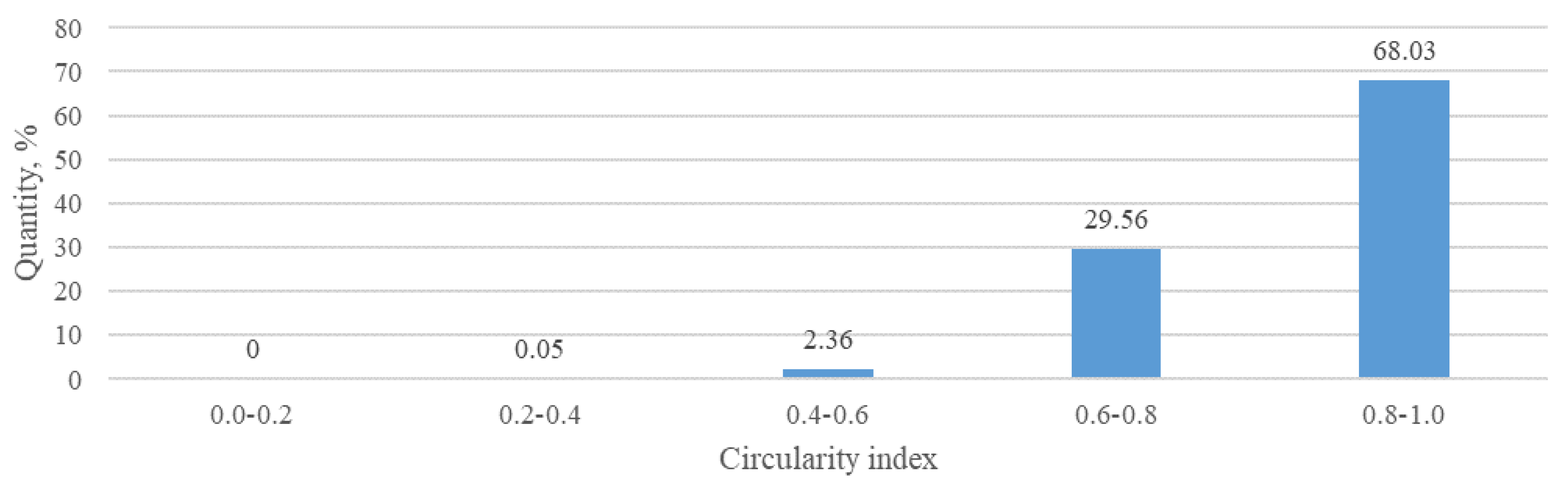
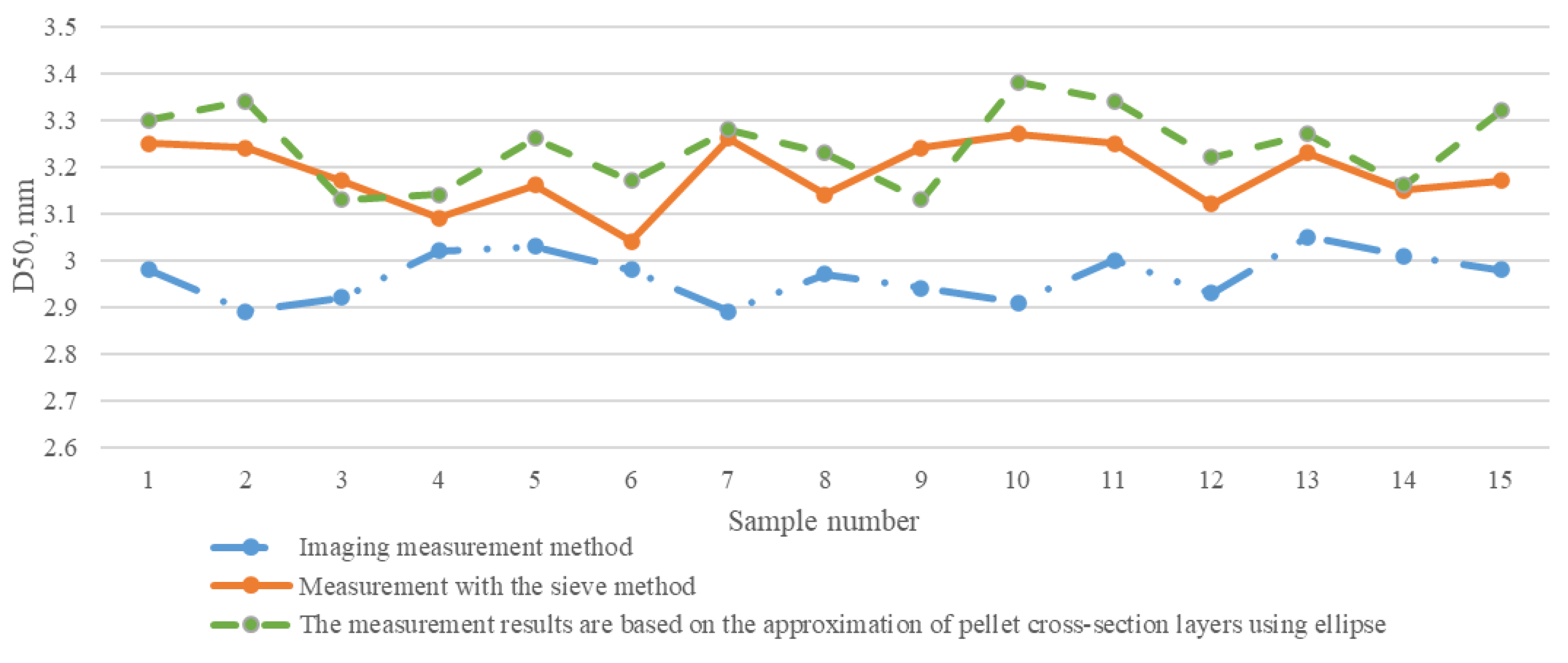
3.1. Evaluation of Shape of Pellets

Depending on the chemical composition of fertilizers, they can be characterized by anisotropic shape. Therefore, ordinary methods of pellet volume by approximation using different geometric shapes introduces discrepancies. For this reason, with any method of pellet volume evaluation, the product’s distribution according to roundness should be known. The distribution of roundness of monoammonium phosphate pellets according to ratio between diagonals of area limited by pellet is provided in Figure 5. During the measurement, 100 different samples taken during the production were analyzed. The graph shows the average of the measurements, and standard squared deviation of measurement < 4%.
After evaluating the results of measuring of roundness of the studied pellets, the assumption can be made that irregularly shaped, elongated pellets are most common throughout all production. Since techniques of processing two-dimensional images cannot take the depth of the image into account, the diameters of pellets, perpendicular to their longitudinal axis, must be thoroughly evaluated. During the examination of shape evaluation, ~1000 pellets were analyzed. A quantity of 10–20 pellets were randomly chosen from each roundness interval of different samples. Every pellet was scanned twice—an image of the largest area limited by the pellet, and an image of the pellet rotated by 90° (principle of pellet evaluation is presented in Figure 6). Results of pellet measuring are provided in Figure 7.
Results received from analysis of monoammonium phosphate pellets indicate that discrepancy of shape of pellets increases with increasing size of a pellet. However, ≤ 95% of all pellets of the material with which we are working are distributed in the interval from 0.2 mm to 1.0 mm. Within these boundaries, roundness of pellets according to ration of diagonals is distributed within boundaries from 0.4 to 0.8. The discrepancy among areas limited by different contours produced according to longitudinal axis that is in the mentioned intervals is < 3%. Because of the contamination of equipment, pellets tend to become smaller during production and it is sufficient to evaluate their shape from one position.

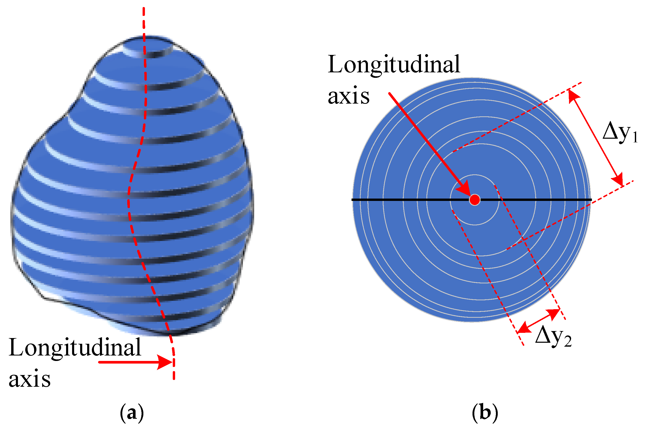
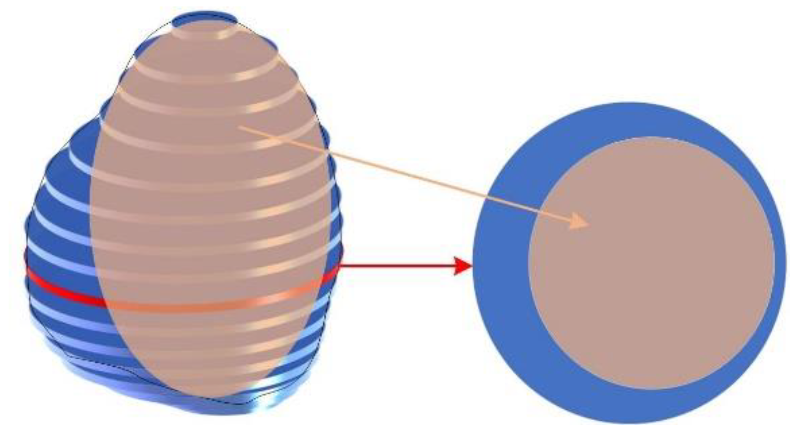
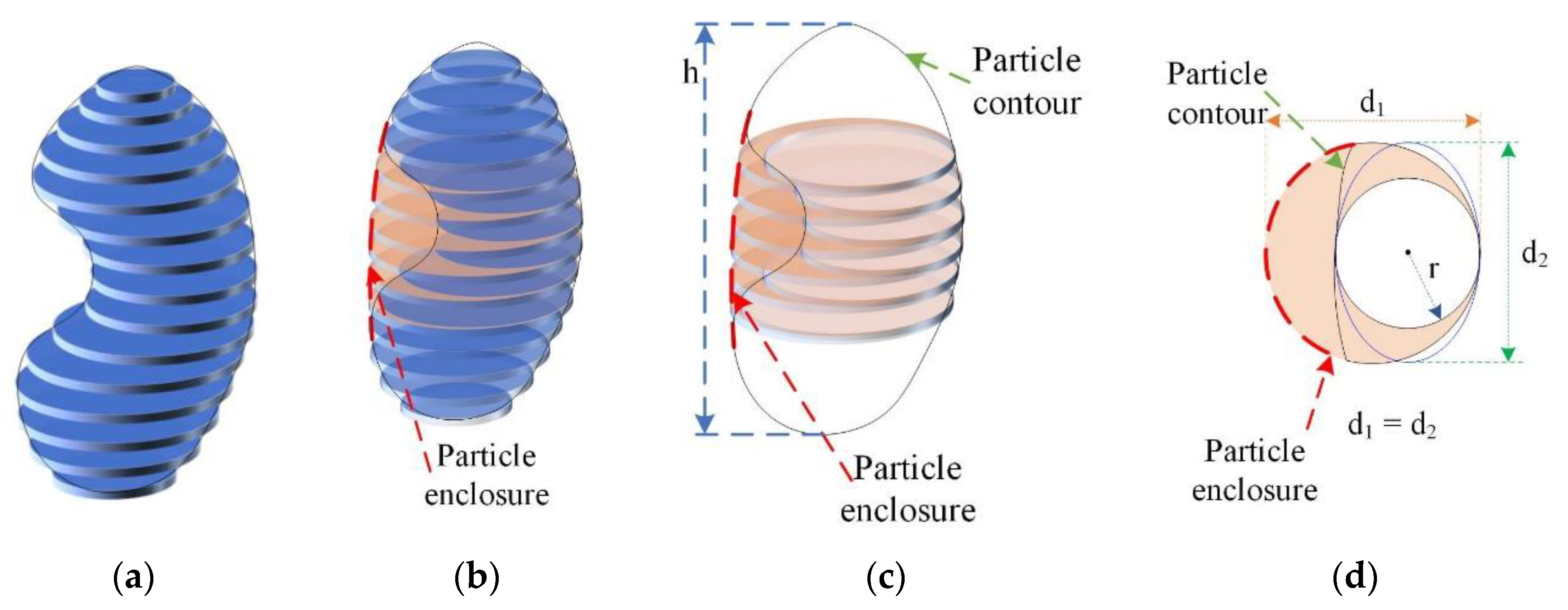
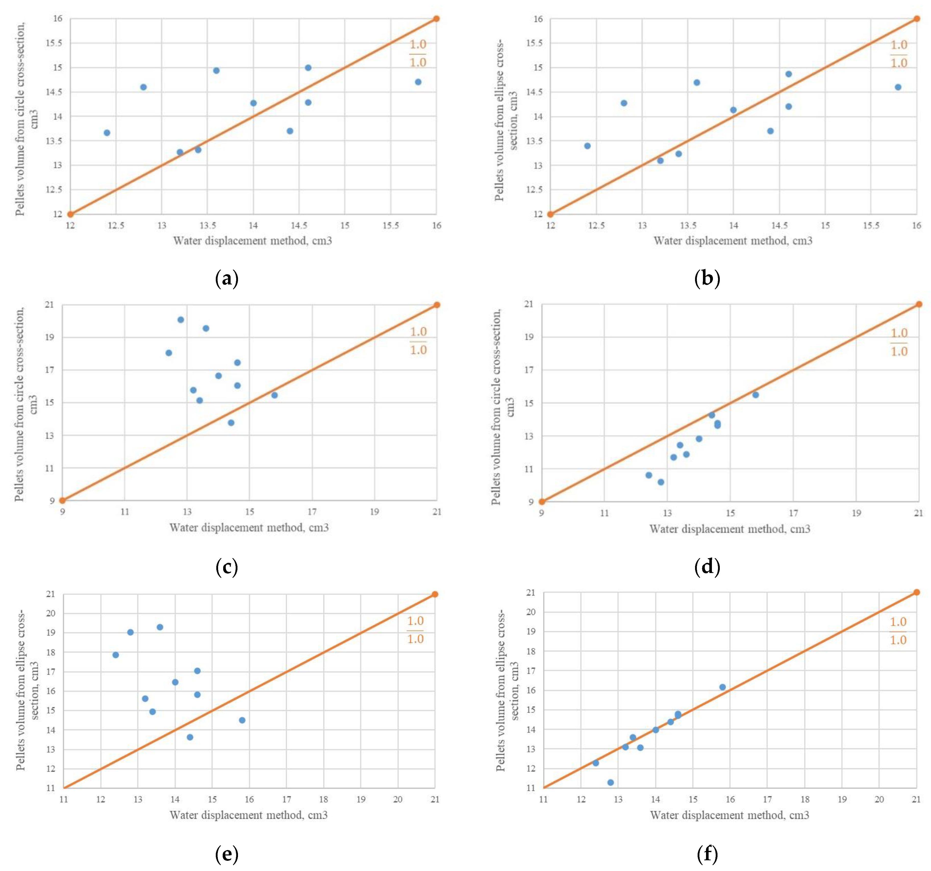
3.2. Estimation of Pellet Volume by Dividing Them into Circular Layers

Based on experiments of pellet analysis, it can be stated that sufficient precision can be achieved when the pellet’s volume is evaluated according to area limited by the pellet’s silhouette. After evaluating examination results it was determined that only in specific cases, when dealing with a pellet’s shape that is very close to ideal, is the ellipsoid volume formula Equation (2) suitable for calculation of pellet volume. Since roundness index of analyzed material is not very high (evidenced by experimental examination, Figure 4), this mathematical expression does not match the real volume limited by pellet. According to the literature [37], the reduction of error of measurements is affected by the division of the analyzed ellipsoid into layers, i.e., dividing its area into narrow regions that are perpendicular to longitudinal axis of ellipse.
The area limited by the pellet’s silhouette is divided into layers of least height. This height is equal to the height of one point of the image. Using this method, the area of circle, limiting every layer, is calculated [37,38] with Equation (3):
S i = π r 2 = π ( Δ y 2 ) 2 ,
where Si—area of circle that limits the layer; Δy—the widthof the ellipse layer (particle scheme in Figure 8).
The measuring method studied by Rashidi and Gholami [37] is based on model of the ideal ellipse, because the ellipsoid consists of sum of volumes of circles Equations (4) and (5):
V i = S i Δ x ,
V = i = 1 n V i ,
where Si—area of circle limiting the layer; Vi—volume of circle limiting the layer; V—volume limited by ellipsoid.
During the examination, the formed models of the regular shaped pellets were scanned using video camera. Pellets of ellipse shape were formed according to measurement results presented in Figure 7—most pellets are elongated. At the beginning of measuring, the calibration of the experimentation equipment was carried out by evaluating the ratio coefficient between points in the image and real size of a pellet—for recalculation of results into SI (metric) system units. In the later stages, after binarization and threshold segmentation operations were carried out in scanned images, the area of the analyzed pellet was distinguished. The general volume of the pellet was calculated by adding up volumes of the separates layers (perpendicular to longitudinal axis of the pellet), whose height is equal to one point of image. The algorithm of the calculation method is presented in Figure 9. Convexity of the was evaluated experimentally. During the examination of pellet models in course of the experiment, it was determined that this threshold value was 0.8, while there were additional calculations carried out for determining the convexity of a pellet.
Additionally, the limited area of the pellet, as ellipsoid, was evaluated during the examination. The received results of the measurements and calculations are presented in Table 1. The results of measuring were compared to data received using the water displacement method. This method is considered to be benchmark method of measuring. Contours of the pellets were also approximated using circular geometric form. The volume of the granules was estimated using the circular approximation method presented in the Figure 1a. Results are presented in graphs of Figure 10.
After evaluation of results of the pellet volume measurements, presented in Figure 1 and Figure 10, it can be stated that approximation using the ellipse limiting the pellet’s area is not a reliable volume measuring method for evaluating the volume of the ellipsoid. In case of ellipsoid approximation, the average of absolute error of measurements is up to 1.258 cm3, while σ = 0.687. When the volume of pellets model is calculated by dividing its area into layers of one point of the image and the limited area of layers is added up, more reliable measurement results are produced because of the lowest possible distance between the adjacent analyzed areas of cross-section. Respectively, the average of absolute error—0.153 cm3 and σ = 0.171. To evaluate the results produced during the experiment, it can be said that applied method of pellet evaluation of analysis of two-dimensional image of a pellet by dividing it into limited areas of cross-section is reliable and assures low MRE (Mean Relative Error) Equation (6):
δ = | 0.15 | | 13.8 | × 100 % 1.109 % .
It was determined that the applied method of pellet shape evaluation is effective with regular geometric shape of a pellet, which rarely matches real irregularities limited by the area of an angled pellet. For evaluation of the shape, 50 samples of same material (monoammonium phosphate) were randomly taken at different point of time of production. Figure 11 provides two dimensional images of scanned irregularly shaped pellets together with statistical graphs of distribution of irregularly shaped pellets in a sample, according to pellet’s roundness.
After evaluating the samples taken in course of the production, it was determined that the statistically most common irregularities of pellet shape were convexity, flatness of shape and various notches. Convexity of shape can be evaluated using the Equation (5) volume calculation formula, where different layers of pellet are treated as circles. However, in such cases each irregularity limited by the region of the pellet silhouette should be positioned in an area limited by > ¾ of the pellet cross-section (Figure 12). When the pellet is flat, evaluation of its volume according to circles, which the cross-section consists of, creates discrepancies of measurements.
The cross-section of flat pellets or pellets with notches with respect to longitudinal axis of pellet is similar to the area limited by ellipse. According to previously presented methods of pellet volume evaluation, where separate layers of pellets are evaluated as circles, it is likely that measurement discrepancy will appear between measurement results, when they are compared to data received using control equipment. In the case of evaluating irregularly shaped pellets, calculation of circle area in place of a notch in the pellet decreases the area of its cross-section and this directly affects the shrinking of pellet volume.

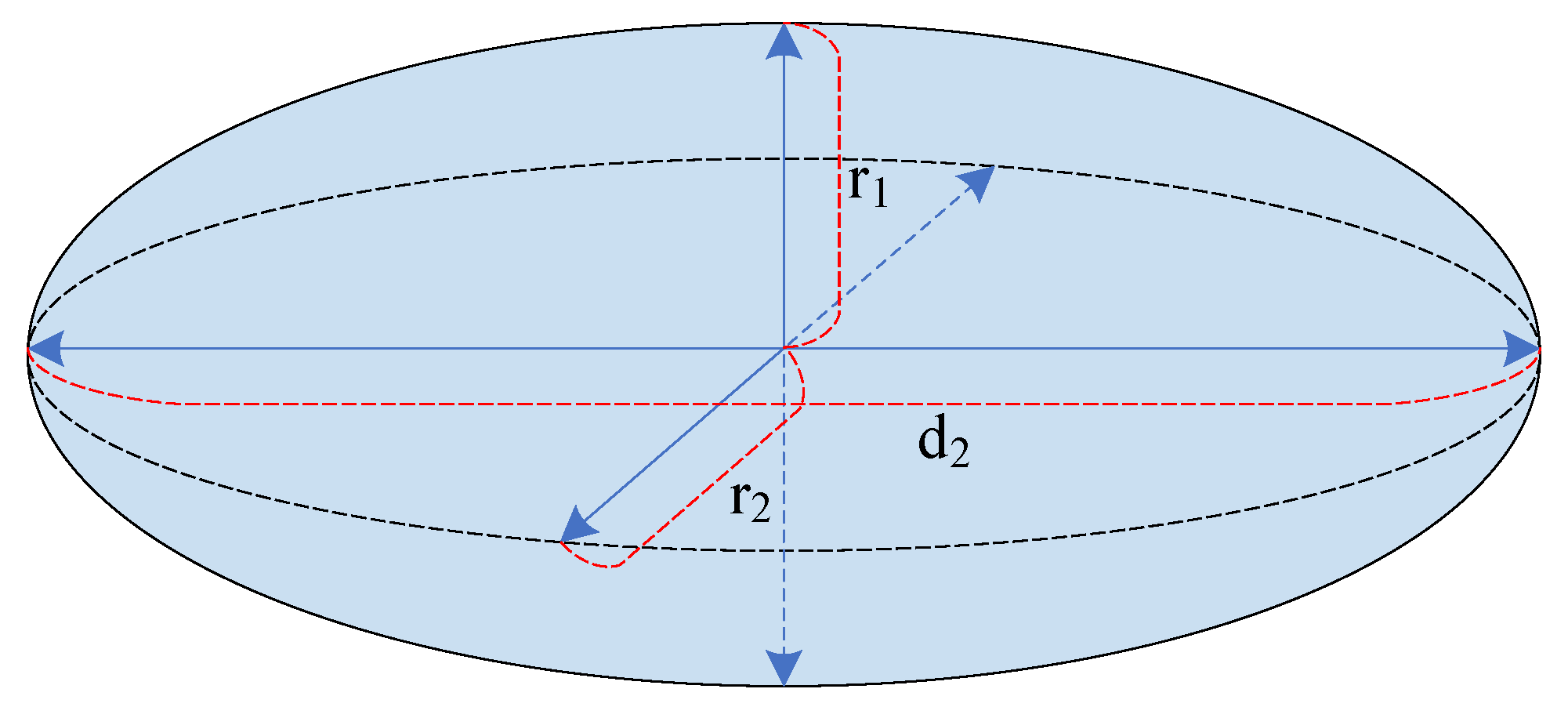
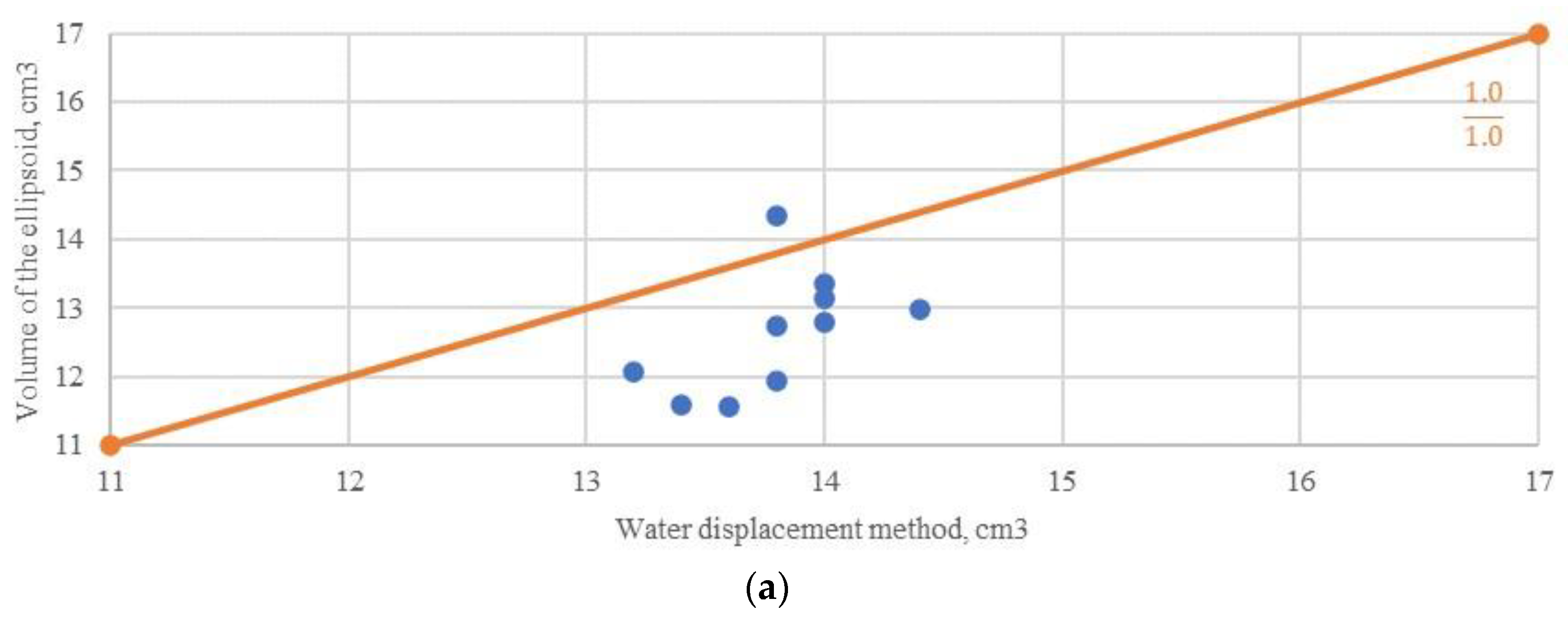
3.3. Estimation of Pellet Volume by Dividing Them into Elliptical Layers

For compensation of pellet volume calculation when the pellet is irregularly shaped, convexity of the area limited by the pellet was evaluated. After filling the notch in the pellet with its convex shape, its depth can be rationally evaluated. The ellipse geometric shape fills the cross-section area of a pellet more precisely. The three-dimensional model of irregular pellet presented in Figure 13.
Based on the pellet model presented in Figure 13, an assumption can be made that the cross-section area of the pellet limited by the envelope line is better overlapped by an ellipse than a circle. The volume is calculated by using both contours of the pellet—the real and notched area limited by the envelope line. The pellets volume is divided into cross-section areas, whose height is equal to one point of the image and which are perpendicular to longitudinal axis; then the pellets volume is calculated by integrating (according to Figure 13) Equations (7) and (8):
S ( h ) = π r d 2 2 ,
V = 0 h S ( h ) dh ,
where S(h)—area of ellipse limiting the layer; r—half of cross-section of real area limited by pellet; d2—diameter of cross-section limited by pellets envelope line; h—length of a pellet, perpendicular to planes of layers that limit it; V—volume limited by pellet.
For testing the reliability of the measuring method evaluating irregularly shaped pellets, models of plasticine were made (Figure 14a). Formed models of the pellets were scanned in two directions, using video camera, with the pellets position covering the largest possible area in relation to position of the video camera and the pellet rotated by 90° from the largest area position. This allowed us to evaluate the reliability of the measuring method by analyzing irregular geometric shapes from different positions in space. Calibrated experimental equipment was used for measuring. After carrying out primary morphological operations in the scanned images, the contour limited by the model was identified (Figure 14b). One of more important objectives of the primary processing is elimination of very small pellets that are in the background of the image and are not affected by gravity. This task is carried out by applying evaluation of the background [39], which allows us to filter out unneeded objects [40].
The general volume of the pellet is calculated by the previously used method of the sum of the separate volumes of layers, whose height is equal to one point of the image. The improved method is based on the calculation of the ellipse-like areas (based on Figure 8 and Figure 13). The received results are presented in Table 2. The measuring data was compared to the method of the layer sum of circle-like pellets. Data received using the water displacement method is considered benchmark. Measuring results are presented in graphs of Figure 15.
According to the calculations results, for the evaluation of volume of the irregularly shaped pellet, the evaluation method of pellet layer area approximation using the ellipse can be selected as a rational choice. The average absolute error when layers are approximated as circles is 1.191 cm3 (when the pellet is evaluated rotated by 90° from position, in which the pellet limits the largest possible area in relation to field of view of the camera), which on average represents < 9% of average volume of a pellet. Average squared deviation respectively was 1.38. While, when approximation of layers was carried out using the ellipse geometric shape, the average absolute error was 0.314 cm3 (when the pellet is evaluated rotated by 90° from position, in which the pellet limits the largest possible area in relation to field of view of the camera) and it represents < 2% of average volume of pellet.
To evaluate the practical value of this method, measurements in a real production line were carried out. Measuring equipment, designed, manufactured and installed in previous works, with linear video camera, LED light and automatic subsystem of sampling was used [34]. Monoammonium phosphate samples (MAP) were analyzed during the experiment. Received results were compared to results received using the sieves method and the method of processing of scanned images (where pellets were approximated using ellipse) (Figure 16, Figure 17 and Figure 18). Same samples were compared during measuring.
The evaluation of the received results showed evident matching of the results with those received from the control equipment. Evaluation of the results of separate samples showed that absolute error does not exceed 0.15 mm of the average size of the pellet (D50). The relative error is less than 5%, when the absolute error of approximation of the pellet using the ellipse is up to 0.37 and relative error is > 12%. Therefore, it can be stated that the proposed method for evaluating separate pellets allows for achieving better matching between the measuring results and control equipment results.

4. Discussion

The received examination results showed that not only the shape of approximation has a great effect on the precision of evaluation, but also the position of the pellet in relation to the video camera. When a less characteristic image of a pellet is scanned, it does not provide sufficient valuable geometric information which could be interpreted correctly. After evaluating measurement results, it was noted that a similar level of discrepancy is found with both approximation of layers using circle and approximation using ellipse. The average absolute error when layers are evaluated as circles was 3.116 cm3, while the relative error is up to 17.40%. When layers are evaluated using the ellipse shape average the absolute error is 2.954 cm3, while the relative error is up to 17.20%. Therefore, the assumption is made that the area and volume of a pellet at a place of notch should be evaluated as a geometric shape of ellipse, because it provides more precise results of measurements. These results can later be used for management of other, more complex processes [41]. The proposed more accurate method of evaluating irregularly shaped pellets can be ensured by implementing a computer vision quality monitoring system in the fertilizer production line. Monitoring the results allows operators to adjust the line parameters that determine the shape of the particles. Ensuring the quality control of production processes determines the quality of the final product. High-quality fertilizer production influences better absorption of useful substances for plants, and more even fertilization.

5. Conclusions

We have provided the results of experiments with the proposed method for evaluation of pellet volume using two-dimensional image processing. After completion of the first experiments it was determined that approximation of irregularly shaped pellets using circular geometric shapes presents a larger amount of error than approximation using ellipsoids. Respectively, when sphere shape approximation is used, the average absolute error is up to 1.258 cm3 (σ = 0.687), while when using ellipsoid, 0.153 cm3 (σ = 0.171). It is more than eight times the difference. Additionally, it must be noted that irregularly shaped pellets were evaluated.
The standard method, which is not precise when irregular shapes are being evaluated, was evaluated according to literature sources. Evaluation of pellet volume by using its cross-section layers whose height is limited by the lowest possible height of scanning equipment provides better results of volume calculation. It was determined that the shape of an elongated ellipse is characteristic to a monoammonium phosphate pellet. Additionally, the most common met irregularities of pellet shape (notches) were evaluated. The proposed method allows for the elimination of discrepancies by evaluating the envelope line of the region limited by the pellet silhouette. After improving approximation of the cross-section using the ellipse geometric shape according to convexity of area limited by the pellet’s silhouette, better results were achieved. This allowed us to reduce relative error from 10.20% to 2.50%. However, in order to achieve these results, it is very important that the more characteristic region of the scanned pellet should be evaluated. When the pellet is rotated by 90° from position in which this pellet limits the largest area in relation to the field of view of the video camera, the error is only up to < 2% of its average volume. The proposed method of pellets analysis makes it possible to achieve high results of indirect measurements with an error of less than 2%. This provides an opportunity for continuous monitoring of production. To ensure reliable results, they can be compared with the data of measurements performed by the direct measurement method (the latter are performed significantly less frequently). In further works it is planned to carry out experiments with pellet ducts of different shapes, which are used to transport pellet for testing.

Author Contributions

Conceptualization, D.A. and A.L.; methodology, A.L. and D.A.; software, A.L. and D.N.; validation, A.L., M.Z., and V.M.; formal analysis, R.S. and J.J., visualization, M.Z., D.N., and D.K.; investigation, A.V., V.M., J.J., and D.K.; resources, A.L. and A.V.; data curation, A.L.; writing—original draft preparation, D.A. and A.L.; writing—review and editing, V.M., D.K. and R.S.; supervision, D.A.; funding acquisition, A.V., M.Z., and D.N. All authors have read and agreed to the published version of the manuscript.

Funding

This research received no external funding.

Conflicts of Interest

The authors declare no conflict of interest.

References

  1. Markovic, S.; Stojanovic, Z.S. Determination of Particle Size Distributions by Laser Diffraction. Tech. New Mater. 2012, 21, 11–20. [Google Scholar]
  2. Witt, W.; Heuer, M.; Schaller, M. In-line particle sizing for process control in new dimensions. China Particuol. 2004, 2, 185–188. [Google Scholar] [CrossRef]
  3. Cornillault, J. Particle Size Analyzer. Appl. Opt. 1972, 11, 265. [Google Scholar] [CrossRef] [PubMed] [Green Version]
  4. Coghill, P.; Millen, M.; Sowerby, B. On-line measurement of particle size in mineral slurries. Miner. Eng. 2002, 15, 83–90. [Google Scholar] [CrossRef]
  5. McClements, D.J. Ultrasonic Measurements in Particle Size Analysis. In Encyclopedia of Analytical Chemistry: Applications, Theory and Instrumentation; John Wiley & Sons, Ltd.: Hoboken, NJ, USA, 2006. [Google Scholar]
  6. Wan, Q.; Jiang, W. Near field acoustic holography (NAH) theory for cyclostationary sound field and its application. J. Sound Vib. 2006, 290, 956–967. [Google Scholar] [CrossRef]
  7. Findlay, W.P.; Peck, G.R.; Morris, K.R. Determination of fluidized bed granulation end point using near-infrared spectroscopy and phenomenological analysis. J. Pharm. Sci. 2005, 94, 604–612. [Google Scholar] [CrossRef]
  8. Petrak, D. Simultaneous Measurements of Particle Size and Velocity with Spatial Filtering Technique In Comparison With Coulter Multisizer and Laser Doppler Velocimetry. In Proceedings of the 4th International Conference on Multiphase Flow, New Orleans, LA, USA, 27 May–1 June 2001; Available online: https://www.parsum.de/wp-content/uploads/2017/10/ConfMPF882.pdf (accessed on 1 March 2020).
  9. Dieter, P.; Stefan, D.; Günter, E.; Michael, K. In-line particle sizing for real-time process control by fibre-optical spatial filtering technique (SFT). Adv. Powder Technol. 2011, 22, 203–208. [Google Scholar] [CrossRef]
  10. Bishop, D. A sedimentation method for the determination of the particle size of finely divided materials (such as hydrated lime). Bur. Stand. J. Res. 1934, 12, 173. [Google Scholar] [CrossRef]
  11. Maab, S.; Rojahn, J.; Emmerich, J.; Kraume, M. On-Line Monitoring Of Fluid Particle Size Distributions In Agitated Vessels Using Automated Image Analysis. In Proceedings of the 14th European Conference on Mixing, Warszawa, Poland, 10–13 September 2012; Available online: https://pdfs.semanticscholar.org/dce5/c4ca8f3f676f6a65132654ff59351b11ee88.pdf (accessed on 1 March 2020).
  12. Lu, Z.; Hu, X.; Lu, Y. Particle Morphology Analysis of Biomass Material Based on Improved Image Processing Method. Int. J. Anal. Chem. 2017, 2017, 1–9. [Google Scholar] [CrossRef]
  13. Hijazi, B.; Cool, S.; Vangeyte, J.; Mertens, K.; Cointault, F.; Paindavoine, M.; Pieters, J. High Speed Stereovision Setup for Position and Motion Estimation of Fertilizer Particles Leaving a Centrifugal Spreader. Sensors 2014, 14, 21466–21482. [Google Scholar] [CrossRef] [Green Version]
  14. Närvänen, T.; Seppälä, K.; Antikainen, O.; Yliruusi, J. A New Rapid On-Line Imaging Method to Determine Particle Size Distribution of Granules. AAPS PharmSciTech 2008, 9, 282–287. [Google Scholar] [CrossRef] [PubMed] [Green Version]
  15. Laitinen, N.; Antikainen, O.; Yliruusi, J. Characterization of particle sizes in bulk pharmaceutical solids using digital image information. AAPS PharmSciTech 2003, 4, 383–391. [Google Scholar] [CrossRef] [PubMed]
  16. Watano, S.; Numa, T.; Miyanami, K.; Osako, Y. On-line Monitoring of Granule Growth in High Shear Granulation by an Image Processing System. Chem. Pharm. Bull. 2000, 48, 1154–1159. [Google Scholar] [CrossRef] [PubMed]
  17. Kumari, R.; Rana, N. Particle Size and Shape Analysis using Imagej with Customized Tools for Segmentation of Particles. Int. J. Eng. Res. 2015, 4, 247–250. [Google Scholar]
  18. Mazzoli, A.; Favoni, O. Particle size, size distribution and morphological evaluation of airborne dust particles of diverse woods by Scanning Electron Microscopy and image processing program. Powder Technol. 2012, 225, 65–71. [Google Scholar] [CrossRef]
  19. Habrat, M.; Mlynarczuk, M. Object Retrieval in Microscopic Images of Rocks Using the Query by Sketch Method. Appl. Sci. 2019, 10, 278. [Google Scholar] [CrossRef] [Green Version]
  20. Okarma, K. Current Trends and Advances in Image Quality Assessment. Elektronika ir Elektrotechnika 2019, 25, 77–84. [Google Scholar] [CrossRef] [Green Version]
  21. Laucka, A.; Adaskeviciute, V.; Valinevicius, A.; Andriukaitis, D. Research of the Equipment Calibration Methods for Fertilizers Particles Distribution by Size Using Image Processing Measurement Method. In Proceedings of the 2018 23rd International Conference on Methods & Models in Automation & Robotics (MMAR), Międzyzdroje, Poland, 27–30 August 2018; pp. 407–412. [Google Scholar]
  22. Vrbančič, G.; Podgorelec, V. Automatic Classification of Motor Impairment Neural Disorders from EEG Signals Using Deep Convolutional Neural Networks. Elektronika ir Elektrotechnika 2018, 24, 3–7. [Google Scholar] [CrossRef]
  23. Forristal, D. Fertiliser Prills or Granules: Which Spread Best? The IFJ Article. 2014. Available online: https://www.teagasc.ie/media/website/publications/2014/Fertiliser_Prills_or_granules.pdf (accessed on 1 March 2020).
  24. Particle Size Result Interpretation: Number vs. Volume Distributions. Available online: https://www.horiba.com/scientific/products/particle-characterization/education/general-information/data-interpretation/number-vs-volume-distributions/ (accessed on 1 March 2020).
  25. ISO 9276-2:2001: Representation of Results of Particle Size Analysis—Part 2: Calculation of Average Particle Sizes/Diameters and Moments from Particle Size Distributions. Available online: https://www.iso.org/standard/33997.html (accessed on 1 March 2020).
  26. ASTM E 799-03 Standard Practice for Determining Data Criteria and Processing for Liquid Drop Size Analysis. Available online: https://www.astm.org/Standards/E799.htm (accessed on 1 March 2020).
  27. International Standard ISO 20998-1:2006 “Measurement and Characterization of Particles by Acoustic Methods”. Available online: https://www.iso.org/standard/39869.html (accessed on 1 March 2020).
  28. Stewart, L.; Bandel, V.A. Uniform Lime and Fertilizer Spreading. Publication about Fertilizers Equipment and Production Process. Available online: https://extension.umd.edu/sites/extension.umd.edu/files/_images/programs/anmp/EB_254_Uniform%20Lime%20and%20Fertilizer%20Spreading.pdf (accessed on 1 March 2020).
  29. Das, S.C.; Behara, S.R.B.; Morton, D.A.V.; Larson, I.; Stewart, P. Importance of particle size and shape on the tensile strength distribution and de-agglomeration of cohesive powders. Powder Technol. 2013, 249, 297–303. [Google Scholar] [CrossRef]
  30. Yu, H.; Ding, Y.; Liu, Z.; Fu, X.; Dou, X.; Yang, C. Development and Evaluation of a Calibrating System for the Application Rate Control of a Seed-Fertilizer Drill Machine with Fluted Rollers. Appl. Sci. 2019, 9, 5434. [Google Scholar] [CrossRef] [Green Version]
  31. Jannat, E.; Arif, A.A.; Hasan, M.M.; Zarziz, A.B.; Rashid, H.A. Granulation techniques & its updated modules. Pharma Innov. J. 2016, 5, 134–141. Available online: https://pdfs.semanticscholar.org/9595/861fa792566927030aabdc9d0cb63a55ce59.pdf (accessed on 1 March 2020).
  32. Le, T.-T.; Miclet, D.; Héritier, P.; Piron, E.; Chateauneuf, A.; Berducat, M. Morphology characterization of irregular particles using image analysis. Application to solid inorganic fertilizers. Comput. Electron. Agric. 2018, 147, 146–157. [Google Scholar] [CrossRef]
  33. Igathinathane, C.; Pordesimo, L.; Columbus, E.; Batchelor, W.; Methuku, S.; Cannayen, I. Shape identification and particles size distribution from basic shape parameters using ImageJ. Comput. Electron. Agric. 2008, 63, 168–182. [Google Scholar] [CrossRef]
  34. Laucka, A.; Adaskeviciute, V.; Andriukaitis, D. Research of the Equipment Self-Calibration Methods for Different Shape Fertilizers Particles Distribution by Size Using Image Processing Measurement Method. Symmetry 2019, 11, 838. [Google Scholar] [CrossRef] [Green Version]
  35. Hogg, R. A Spheroid Model for the Role of Shape in Particle Size Analysis. KONA Powder Part. J. 2015, 32, 227–235. [Google Scholar] [CrossRef] [Green Version]
  36. Riddle, D.F. Calculus and Analytic Geometry; Wadsworth Publishing Company, Inc.: Belmont, CA, USA, 1979; p. 505. ISBN 9780534006266. [Google Scholar]
  37. Rashidi, M.; Gholami, M. Determination of kiwifruit volume using ellipsoid approximation and Image-processing methods. Int. J. Agric. Biol. 2008, 10, 375–380. Available online: https://www.researchgate.net/publication/228409809_Determination_of_kiwifruit_volume_using_ellipsoid_approximation_and_image-processing_methods (accessed on 2 March 2020).
  38. Sabliov, C.M.; Boldor, D.; Keener, K.M.; Farkas, B.E. Image processing method to determine surface area and volume of axi-symmetric agricultural products. Int. J. Food Prop. 2002, 5, 641–653. [Google Scholar] [CrossRef]
  39. Lech, P.; Okarma, K. Prediction of the Optical Character Recognition Accuracy based on the Combined Assessment of Image Binarization Results. Elektronika ir Elektrotechnika 2015, 21, 62–65. [Google Scholar] [CrossRef] [Green Version]
  40. Khitas, M.; Ziet, L.; Bouguezel, S. Improved Degraded Document Image Binarization Using Median Filter for Background Estimation. Elektronika ir Elektrotechnika 2018, 24, 82–87. [Google Scholar] [CrossRef] [Green Version]
  41. Andriukaitis, D.; Laucka, A.; Valinevicius, A.; Zilys, M.; Markevicius, V.; Navikas, D.; Sotner, R.; Petrzela, J.; Jerabek, J.; Herencsar, N.; et al. Research of the Operator’s Advisory System Based on Fuzzy Logic for Pelletizing Equipment. Symmetry 2019, 11, 1396. [Google Scholar] [CrossRef] [Green Version]
Figure 1. Models of pellet approximation: (a,b)—pellet is approximated using a circle drawn around it and a circle drawn inside of it; (c,d)—pellet is approximated using best fit rectangle drawn around it and rectangle drawn inside of it; (e,f)—pellet is approximated using a ellipse drawn around it and a ellipse drawn inside of it.
Applsci 10 02650 g001
Figure 2. Connection between pellet and the shape that is being approximated: (a) area of discrepancy between real area of irregular pellet and circle shaped approximation is marked by the shaded area; (b) left side—real area limited by pellet (S1) and perimeter (P1); right side—circle shape formed from the area of pellet.
Applsci 10 02650 g002
Figure 3. Similarity of results of pellet approximation model and control equipment. (a) Control measuring equipment consisting of a set of sieves with different diameter holes; (b) the width of pellet approximation shape matches the diameter of a hole of a sieve.
Applsci 10 02650 g003
Figure 4. The ellipse model.
Applsci 10 02650 g004
Figure 5. Distribution of monoammonium pellets according to roundness (ratio of diagonals of area limited by pellet’s silhouette).
Applsci 10 02650 g005
Figure 6. (a) The pellet is scanned using a 90° angle between the camera’s field of view and the longitudinal axis of the pellet, when we receive the largest area limited by the pellet and image rotated by 90°; (b) evaluation of discrepancy of pellet overlapping area according to averages of areas.
Applsci 10 02650 g006
Figure 7. Average discrepancy of area limited by the pellet’s silhouette when pellets are evaluated according to their size and roundness.
Applsci 10 02650 g007
Figure 8. The layering of an ellipse: (a) side view of an ellipse model; (b) top view of ellipse model.
Applsci 10 02650 g008
Figure 9. Algorithm for calculation of pellet volume (pellets divided into layers).
Applsci 10 02650 g009
Figure 10. Measuring of volume of formed pellet model based on imaging method of processing of digital images: (a) ratio between results produced by approximation of ellipsoid volume method and water displacement method; (b) ratio between results produced by approximation of pellet volume by dividing pellet’s volume into layers of circles and water displacement method.
Applsci 10 02650 g010aApplsci 10 02650 g010b
Figure 11. Analysis of example of pellets sample: (a) distribution of pellets of first sample according to roundness; (b) distribution of pellets of second sample according to roundness.
Applsci 10 02650 g011
Figure 12. Largest possible ellipse, whose volume is limited by region of pellet, is drawn inside of a pellet.
Applsci 10 02650 g012
Figure 13. Three-dimensional (3D) model of irregular pellet: (a) the pellet’s volume consists of the sum of layer circles; (b) shape of the regular pellet is limited by pellet envelope line; (c) discrepancy between irregular volume and volume limited by envelope line; (d) cross-section of pellet limited by its envelope line.
Applsci 10 02650 g013
Figure 14. (a) Models of analyzed pellets; (b) distinguishing of shape parameters of analyzed model of pellet.
Applsci 10 02650 g014
Figure 15. Measuring of volume of formed pellet models based on method of image processing. All graphs present comparison of results to results received using water displacement volume evaluation method: (a) cross-sections of pellet model layers approximated using circles; (b) cross-sections of pellet model layers approximated using ellipses. In the (a,b) graphs, particle volume calculation was made by evaluating 2 images (largest area and rotated by 90°). In (c,d)—cross-sections of pellet model layers approximated using circles from 1 image (largest area or rotated by 90°). In (e,f)—cross-sections of pellet model layers approximated using ellipses from 1 image (largest area or rotated by 90°).
Applsci 10 02650 g015
Figure 16. Distribution of pellets according to volume.
Applsci 10 02650 g016
Figure 17. Distribution of pellets according to roundness.
Applsci 10 02650 g017
Figure 18. Average diameter of pellet from different samples (D50).
Applsci 10 02650 g018
Table 1. Calculation of volume of pellet model (pellet was divided into circular layers).
Water Displacement MethodMethod for Dividing Pellets into Circular Layers ΔV2, cm3ΔV3, cm3
Sample no.Length of pellet, mmWidth of pellet, mmVolume V1, cm3Length of pellet, mmWidth of pellet, mmVolume V2, cm3Volume V3 1, cm3 | V 1 V 2 | , cm3 | V 1 V 3 | , cm3
180.418.013.881.1118.3714.1114.330.310.52
268.317.613.469.3817.8613.1811.580.221.82
349.120.713.649.6521.0913.3611.560.242.04
453.420.613.853.9021.2613.8512.750.051.05
556.120.814.056.4621.0914.0013.140.010.86
661.418.613.262.4119.2212.9312.070.271.13
774.018.214.074.1418.5414.0113.340.010.66
874.717.814.075.1618.0314.0112.790.011.21
966.919.114.467.1719.2214.2012.990.201.41
1064.818.313.865.1318.7113.5811.930.221.87
MAE, cm31.2580.153
SSE6.8721.711
σ20.6870.171
RMSE1.3510.191
1 Volume of ellipsoid (area of ellipse approximated using ellipse).
Table 2. Differences between calculation of volume of pellets using direct method and pellet division to circular and elliptical layers.
Sample no.Sample PositionVolume V1 2, cm3Volume V2 3, cm3 | V 1 V 2 | , cm3Volume V3 4, cm3 | V 1 V 3 | , cm3Volume V4 5, cm3 | V 1 V 4 | , cm3Volume V5 6, cm3 | V 1 V 5 | , cm3
1Largest area 112.814.601.8014.271.4720.097.2919.026.22
Rotated by 90°10.22.611.291.51
2Largest area 113.614.941.3414.691.0919.565.9619.35.7
Rotated by 90°11.891.7113.060.54
3Largest area 112.413.671.2713.401.0018.075.6717.875.47
Rotated by 90°10.611.7912.290.11
4Largest area 115.814.701.1014.601.2015.450.3514.511.29
Rotated by 90°15.50.316.180.38
5Largest area 113.413.320.0813.230.1715.141.7414.941.54
Rotated by 90°12.440.9613.610.21
6Largest area 114.615.000.4014.870.2717.462.8617.062.46
Rotated by 90°13.780.8214.790.19
7Largest area 113.213.270.0713.100.1015.792.5915.612.41
Rotated by 90°11.731.4713.110.09
8Largest area 114.014.270.2714.140.1416.652.6516.462.46
Rotated by 90°12.831.1713.990.01
9Largest area 114.413.700.7013.700.7013.790.6113.630.77
Rotated by 90°14.280.1214.40
10Largest area 114.614.280.3214.200.4016.041.4415.821.22
Rotated by 90°13.630.9714.70.1
Largest areaMAE0.735 0.654 3.116 2.954
RMSE0.932 0.811 3.851 3.537
Rotated by 90°MAE0.735 0.654 1.191 0.314
RMSE0.932 0.811 1.380 0.532
1 Pellet model rotated to limit the largest area in relation to camera. 2 Volume of pellet model calculated using water displacement method. 3 Cross-section layers of pellet models approximated using circles, while diagonals are evaluated according to information of different images. 4 Cross-section layers of pellet models approximated using ellipses, while diagonals are evaluated according to information of different images. 5 Pellet model cross-section layers approximated using circles. 6 Pellet model cross-section layers approximated using ellipses.

