Abstract
A nanofocusing optical system—referred to as 100 exa—for an X-ray free-electron laser (XFEL) was developed to generate an extremely high intensity of 100 EW/cm2 (1020 W/cm2) using total reflection mirrors. The system is based on Kirkpatrick-Baez geometry, with 250-mm-long elliptically figured mirrors optimized for the SPring-8 Angstrom Compact Free-Electron Laser (SACLA) XFEL facility. The nano-precision surface employed is coated with rhodium and offers a high reflectivity of 80%, with a photon energy of up to 12 keV, under total reflection conditions. Incident X-rays on the optics are reflected with a large spatial acceptance of over 900 μm. The focused beam is 210 nm × 120 nm (full width at half maximum) and was evaluated at a photon energy of 10 keV. The optics developed for 100 exa efficiently achieved an intensity of 1 × 10²⁰ W/cm2 with a pulse duration of 7 fs and a pulse energy of 150 μJ (25% of the pulse energy generated at the light source). The experimental chamber, which can provide different stage arrangements and sample conditions, including vacuum environments and atmospheric-pressure helium, was set up with the focusing optics to meet the experimental requirements.
1. Introduction
Hard X-ray free-electron laser (XFEL) sources [1,2,3,4,5] have successfully generated extremely high-peak brilliance unachieved by existing synchrotron radiation sources. Focusing optics to further enhance the pulse intensity is a particularly useful tool for XFEL experiments. There have been several reports on hard XFEL focusing optics for producing high-intensity pulses utilizing diffractive [6,7], reflective [8,9] and refractive [10,11] optics. Among these alternatives, total reflection optics possess remarkable properties in terms of achromaticity, high efficiency and high tolerance under intense XFEL irradiation.
We had previously developed a two-stage focusing optics system [9] that achieves a focus size of 50 nm and an extremely high intensity of 1 × 10²⁰ W/cm2 at the SPring-8 Angstrom Compact Free-Electron Laser (SACLA) XFEL facility [2]. This optics system utilized nano-precision figured mirrors with an elliptical cylinder shape in Kirkpatrick-Baez (K-B) geometry [12]. Although two-stage focusing optics have successfully contributed to the observation of nonlinear X-ray optical phenomena [13,14,15,16], we encountered several practical challenges in the operation of this system (such as stability, repeatability and alignment) because the focusing condition of the system is highly sensitive to mirror misalignment. Furthermore, the optics system had a low throughput of less than 10% because it had a small spatial acceptance.
In this study, we report the development of a highly stable, high-throughput focusing system that achieves a high intensity of 1 × 10²⁰ W/cm2 (comparable to that of our previous two-stage focusing system) by utilizing single-stage K-B optics optimized for BL3 of SACLA. The system’s large spatial acceptance mirrors of over 900 μm enabled a threefold increase in pulse energy of 150 μJ relative to the previous system, a high intensity of 1 × 10²⁰ W/cm2 at a photon energy of 10 keV and a highly stable beam for over 13.5 h, while achieving a focal spot of approximate dimensions 210 nm × 120 nm (full width at half maximum (FWHM)).
2. Design
2.1. Optics
The optical parameters of the elliptical cylinder shaped focusing mirrors designed for the optical system are summarized in Table 1. The focusing system has a wide spatial acceptance of 970 μm and 920 μm in the vertical and horizontal directions, respectively, which is considerably larger than the incident beam size of 450 μm (FWHM) at EH5 of BL3 at a photon energy of 10 keV. The designed K-B optics have an aperture receiving 80% of the incident pulse energy at a photon energy of 10 keV. We designed the working distance, (length between the downstream edge of the optics and the focus), to be 115 mm, which is long enough to conduct various experiments such as two-color double-pulse experiments and X-ray non-linear optics experiments. The focused beam sizes at a photon energy of 10 keV were geometrically calculated to be 182 and 87 nm (FWHM) using a demagnification ratio based on the light source size and the focal lengths. The focus size is broader than that of the two-stage focusing system because of the moderate demagnification factor. At a photon energy of 10 keV, the calculated focus sizes are three times larger than the diffraction-limited beam sizes of 56 and 28 nm (FWHM) determined using the numerical aperture of the optical system. These optics are advantageous for maintaining the optimized focusing condition because the alignment tolerances of both the incident angle and the focal length are approximately 10 times larger than those of the previous two-stage focusing optics system.

Table 1.
Optical parameters of the focusing mirrors.
The incident angles of the mirrors were designed for use under total reflection conditions of up to 12 keV. Figure 1a presents the calculated reflectivity of the mirrors plotted against the incident photon energy. The reflectivity curves for a rhodium surface coating with a density that is 100% of the bulk density are presented in Figure 1b,c. The reflectivity of the two mirrors is calculated to be 80% up to a photon energy of 12 keV and above 50% at a photon energy of 15 keV. The rhodium-coated mirrors are free from absorption edge within a photon energy range of 5–15 keV. The radiation dose to the rhodium in the optical system is estimated to be well below the threshold level for radiation damage from intense XFEL [17]. With these design parameters, the pulse energy, fluence and intensity of the focus were calculated to be ~200 μJ, 2 × 10⁶ J/cm2 and 2 × 10²⁰ W/cm2 at a photon energy of 10 keV, when the incident pulse energy to the optics and the pulse duration were assumed to be 300 μJ and 7 fs.
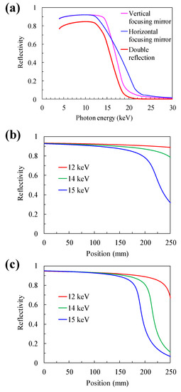
Figure 1.
Calculated reflectivity of designed mirrors. (a) Dependence of reflectivity on the incident photon energy. (b) Dependence of reflectivity on the surface position of the vertical focusing mirrors and (c) the horizontal focusing mirrors. Position 0 mm shows the upstream edge of the focusing mirror. The change in reflectivity is due to variation in the incident angle along the elliptical cylinder surface.
2.2. Mirrors and Sample Chambers
The apparatus developed consists of two independent vacuum chambers—one for the mirrors and the other for the sample. The vacuum chambers are separated by a beryllium window, which protects the mirror surfaces from contaminants from the sample chamber, including particles produced via the ablation of sample materials. The beryllium window with a thickness of ~75 μm is made using a physical vapor deposition method. The mirror chamber was designed such that the mirrors can be operated under high vacuum conditions below 10−5 Pa. In the mirror chamber, we installed stable, high-precision alignment mechanics. Greaseless driving mechanisms with stepper motors are used in all alignment stages of the mirrors, including a linear translational stage utilizing a solid lubricant. The rotating stages, which are composed of a precision linear actuator, with a precision of 10 nm/step (full-step drive) and a flexure hinge at the rotation center, are employed in the alignment of incident angles and perpendicularity between the mirrors. These stages are operated at a precision higher than 0.1 μrad using a harmonic drive gear and a micro-step drive control, while the driving mechanics of the incident angles need to be stabilized at a level of 0.1 μrad to obtain high pointing stability of the optical system.
The sample chamber has an effective space of over 100 mm in length from the beryllium window to the focal point, as shown in Figure 2. The typical vacuum pressure of this chamber is 0.1–1 Pa, and it can be evacuated using a turbo-molecular pump. The sample environment can also be operated under atmospheric pressure helium conditions depending on the sample requirements of the experiments. Various sample stages and sample supply systems, including a liquid jet injector, can be placed in the space around the focal point.
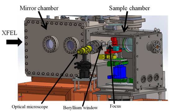
Figure 2.
Schematic drawing of the mirror and the sample chamber. The wall on the near side of the sample chamber is presented as transparent to show the inside of the chamber. A beryllium window separates the mirror and sample chambers. An optical microscope is used to observe the sample at the focus from outside the vacuum chamber. Various sample environments, stage arrangements and sample supply systems can be operated utilizing a 100-mm space upstream of the focus. Both the downstream side and the upper side and one lateral side of the sample chamber can be altered to have a large exit port allowing the data collection for forward scattering geometry, X-ray diffraction and X-ray emission spectroscopy. Furthermore, the sample chamber can be altered based on experimental requests while keeping the mirror chamber unchanged.
The mirror manipulators and sample scanning stages are mounted on a granite surface plate. These stage system and the chambers with the vacuum pumps are connected through bellows and sustained independently on the floor. Therefore, the effect of vibration from the vacuum pumps on the stage systems is minimized.
3. Evaluations at SPring-8 Angstrom Compact Free-Electron Laser (SACLA)
3.1. Evaluation of Focusing Optics
The designed mirrors were fabricated using an ultra-precise computer-controlled process [18] with a surface figure precision (figure error) of 0.30 to 0.52 nm root mean square (RMS) and surface roughness of 0.11 to 0.14 nm RMS. The properties of the focused beam were evaluated at EH5, BL3 of SACLA. The focusing mirrors were aligned using a Foucault knife-edge test [19], with a 200 μm diameter gold wire. For focusing a beam size of 100 nm (FWHM), the alignment tolerances of the horizontal mirror (which are more severe than those of the vertical mirror) were estimated to be ±1.6 μrad in the incident angles, ±10 μrad in perpendicularity between the mirrors and ±2 mm in the focal length at a relatively high photon energy of 12 keV.
Intensity distributions of the focus were measured via the knife-edge scanning method using the wire. The typical focused beam profiles obtained at a photon energy of 10 keV are presented in Figure 3. To prevent ablation of the wire by the intense focused beam, the incident pulse energy for the mirrors was adequately attenuated with silicon attenuation plates. We applied single-crystal silicon attenuators with a total thickness of 1.3 mm and mirror polishing surfaces to avoid influences on focuses beam sizes. The shot-to-shot fluctuations of the incident pulse energy to the mirrors were measured with an intensity monitor [20] and were normalized to eliminate their influence on the profile measurements. The typical beam sizes observed, 210 nm × 120 nm (FWHM), in the vertical and horizontal directions, show most of the reflected pulse energy concentrated at the main peak and low-intensity distributions around the main peak. The effect of vibration from the vacuum pump on the focused beam size is negligibly small. We estimated that 50% beam power width are 135 nm and 85 nm in the vertical and horizontal directions, respectively. The width of the beam is defined as the distance between the points of the knife-edge scan profiles that are 25% and 75% of the total beam power. The focused beam had a pulse energy of 150 μJ, which is 25% of the pulse energy generated at the XFEL light source. From these measured values, the fluence and intensity of the focused pulses reached 8 × 10⁵ J/cm2 and 1 × 10²⁰ W/cm2, assuming a pulse duration of 7 fs [21,22].
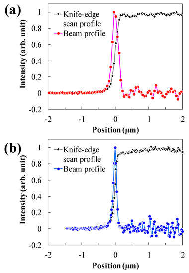
Figure 3.
Typical intensity distributions of focused beam at a photon energy of 10 keV measured using the knife-edge scanning method. The focused beam size of 210 nm × 120 nm (full width half maximum (FWHM)) was evaluated in the (a) vertical direction and (b) horizontal direction. 30 shot intensities were averaged for each data point at an X-ray free-electron laser (XFEL) repetition rate of 30 Hz.
3.2. Stability of the Focused Beam
The stability of the focused beam was assessed in terms of size, position and profile, as shown in Figure 4. The shot-to-shot positional displacement of the focused pulses was less than the measured beam size because the profile measured using the knife-edge scanning method is an average of many pulses. As shown in Figure 4a–c, the beam sizes and profiles in both the vertical and horizontal directions were maintained for over 13.5 h after the alignment of the mirrors. Regarding the focus position in the same evaluation, the positional displacement observed was about 2.5 μm and 0.4 μm in the vertical and horizontal directions, respectively, as shown in Figure 4b,c. The evaluation results for the focal size, position and profile show sufficient stability for most of the XFEL experiments in which a sample is destroyed via ablation using an extremely intense single pulse.
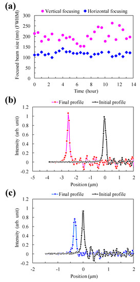
Figure 4.
Measured stability of focused beam. (a) Time dependence of focused beam size. Root-mean-square deviation was 28 nm and 9 nm in the vertical and horizontal directions. (b) Focused beam profiles observed during stability evaluation, in the vertical direction and (c) horizontal direction.
4. Conclusions
We demonstrate a highly-efficient single-stage K-B optics that generates intense XFEL focused pulses. The focused beam evaluated achieved a high fluence of 8 × 10⁵ J/cm2 and an intensity of 1 × 10²⁰ W/cm2, with a significantly improved pulse energy of 150 μJ and stable beam size. Recently, nanofocusing optics for extremely high intensities of 1021 W/cm2 have been reported [7], with multilayer mirrors having a narrow bandpass. In contrast, the optics system in this study, with total reflection mirrors, is applicable for a variety of XFEL experiments, such as two-color double-pulse experiments [23,24], which require extremely high intensity, achromaticity and highly improved stability.
Author Contributions
Optical design of the focusing mirrors: H.Y., Y.I., T.K. and H.O. Design of the mirror alignment mechanism: H.Y., T.K. and H.O. Sample chamber design: Y.I., T.O., I.I., K.T. and M.Y. Evaluation of the focusing beam: Y.I., T.O. and I.I. Writing—original draft preparation: H.Y. Writing—review and editing: M.Y. Project administration: M.Y. All authors have read and agreed to the final version of the manuscript.
Funding
This research received no external funding.
Acknowledgments
We would like to acknowledge the supporting members of SACLA facility. The XFEL experiments were performed at the BL3 of SACLA with the approval of the Japan Synchrotron Radiation Research Institute (JASRI) (Proposal No. 2017B8086).
Conflicts of Interest
The authors declare no conflict of interest.
References
- Emma, P.; Akre, R.; Arthur, J.; Bionta, R.; Bostedt, C.; Bozek, J.; Brachmann, A.; Bucksbaum, P.; Coffee, R.; Decker, F.-J.; et al. First lasing and operation of an ångstrom-wavelength free-electron laser. Nat. Photonics 2010, 4, 641–647. [Google Scholar] [CrossRef]
- Ishikawa, T.; Aoyagi, H.; Asaka, T.; Asano, Y.; Azumi, N.; Bizen, T.; Ego, H.; Fukami, K.; Fukui, T.; Furukawa, Y.; et al. A compact X-ray free-electron laser emitting in the sub-ångström region. Nat. Photonics 2012, 6, 540–544. [Google Scholar] [CrossRef]
- Kang, H.-S.; Min, C.-K.; Heo, H.; Kim, C.; Yang, H.; Kim, G.; Nam, I.; Baek, S.Y.; Choi, H.-J.; Mun, G.; et al. Hard X-ray free-electron laser with femtosecond-scale timing jitter. Nat. Photonics 2017, 11, 708–713. [Google Scholar] [CrossRef]
- Tschentscher, T.; Bressler, C.; Grünert, J.; Madsen, A.; Mancuso, A.P.; Meyer, M.; Scherz, A.; Sinn, H.; Zastrau, U. Photon beam transport and scientific instruments at the European XFEL. Appl. Sci. 2017, 7, 592. [Google Scholar] [CrossRef]
- Milne, C.J.; Schietinger, T.; Aiba, M.; Alarcon, A.; Alex, J.; Anghel, A.; Arsov, V.; Beard, C.; Beaud, P.; Bettoni, S. SwissFEL: The Swiss X-ray free electron laser. Appl. Sci. 2017, 7, 720. [Google Scholar] [CrossRef]
- David, C.; Gorelick, S.; Rutishauser, S.; Krzywinski, J.; Vila-Comamala, J.; Guzenko, V.A.; Bunk, O.; Färm, E.; Ritala, M.; Cammarata, M. Nanofocusing of hard X-ray free electron laser pulses using diamond based Fresnel zone plates. Sci. Rep. 2011, 1, 57. [Google Scholar] [CrossRef]
- Matsuyama, S.; Inoue, T.; Yamada, J.; Kim, J.; Yumoto, H.; Inubushi, Y.; Osaka, T.; Inoue, I.; Koyama, T.; Tono, K. Nanofocusing of X-ray free-electron laser using wavefront-corrected multilayer focusing mirrors. Sci. Rep. 2018, 8, 1–10. [Google Scholar] [CrossRef]
- Yumoto, H.; Mimura, H.; Koyama, T.; Matsuyama, S.; Tono, K.; Togashi, T.; Inubushi, Y.; Sato, T.; Tanaka, T.; Kimura, T. Focusing of X-ray free-electron laser pulses with reflective optics. Nat. Photonics 2013, 7, 43. [Google Scholar] [CrossRef]
- Mimura, H.; Yumoto, H.; Matsuyama, S.; Koyama, T.; Tono, K.; Inubushi, Y.; Togashi, T.; Sato, T.; Kim, J.; Fukui, R. Generation of 1020 W cm-2 hard X-ray laser pulses with two-stage reflective focusing system. Nat. Commun. 2014, 5, 1–5. [Google Scholar] [CrossRef]
- Schropp, A.; Hoppe, R.; Meier, V.; Patommel, J.; Seiboth, F.; Lee, H.J.; Nagler, B.; Galtier, E.C.; Arnold, B.; Zastrau, U. Full spatial characterization of a nanofocused x-ray free-electron laser beam by ptychographic imaging. Sci. Rep. 2013, 3, 1633. [Google Scholar] [CrossRef]
- Seiboth, F.; Schropp, A.; Scholz, M.; Wittwer, F.; Rödel, C.; Wünsche, M.; Ullsperger, T.; Nolte, S.; Rahomäki, J.; Parfeniukas, K. Perfect X-ray focusing via fitting corrective glasses to aberrated optics. Nat. Commun. 2017, 8, 1–5. [Google Scholar] [CrossRef]
- Kirkpatrick, P.; Baez, A.V. Formation of optical images by X-rays. JOSA 1948, 38, 766–774. [Google Scholar] [CrossRef]
- Tamasaku, K.; Shigemasa, E.; Inubushi, Y.; Katayama, T.; Sawada, K.; Yumoto, H.; Ohashi, H.; Mimura, H.; Yabashi, M.; Yamauchi, K. X-ray two-photon absorption competing against single and sequential multiphoton processes. Nat. Photonics 2014, 8, 313–316. [Google Scholar] [CrossRef]
- Yoneda, H.; Inubushi, Y.; Yabashi, M.; Katayama, T.; Ishikawa, T.; Ohashi, H.; Yumoto, H.; Yamauchi, K.; Mimura, H.; Kitamura, H. Saturable absorption of intense hard X-rays in iron. Nat. Commun. 2014, 5, 1–5. [Google Scholar] [CrossRef]
- Yoneda, H.; Inubushi, Y.; Nagamine, K.; Michine, Y.; Ohashi, H.; Yumoto, H.; Yamauchi, K.; Mimura, H.; Kitamura, H.; Katayama, T. Atomic inner-shell laser at 1.5-ångström wavelength pumped by an X-ray free-electron laser. Nature 2015, 524, 446–449. [Google Scholar] [CrossRef]
- Ghimire, S.; Fuchs, M.; Hastings, J.; Herrmann, S.C.; Inubushi, Y.; Pines, J.; Shwartz, S.; Yabashi, M.; Reis, D.A. Nonsequential two-photon absorption from the K shell in solid zirconium. Phys. Rev. A 2016, 94, 043418. [Google Scholar] [CrossRef]
- Koyama, T.; Yumoto, H.; Miura, T.; Tono, K.; Togashi, T.; Inubushi, Y.; Katayama, T.; Kim, J.; Matsuyama, S.; Yabashi, M. Damage threshold of coating materials on x-ray mirror for x-ray free electron laser. Rev. Sci. Instrum. 2016, 87, 051801. [Google Scholar] [CrossRef]
- Yamauchi, K.; Mimura, H.; Inagaki, K.; Mori, Y. Figuring with subnanometer-level accuracy by numerically controlled elastic emission machining. Rev. Sci. Instrum. 2002, 73, 4028–4033. [Google Scholar] [CrossRef]
- Malacara, D. Optical Shop Testing; John Wiley & Sons: Hoboken, NJ, USA, 2007; Volume 59, pp. 275–297. [Google Scholar]
- Tono, K.; Kudo, T.; Yabashi, M.; Tachibana, T.; Feng, Y.; Fritz, D.; Hastings, J.; Ishikawa, T. Single-shot beam-position monitor for x-ray free electron laser. Rev. Sci. Instrum. 2011, 82, 023108. [Google Scholar] [CrossRef]
- Inubushi, Y.; Inoue, I.; Kim, J.; Nishihara, A.; Matsuyama, S.; Yumoto, H.; Koyama, T.; Tono, K.; Ohashi, H.; Yamauchi, K. Measurement of the X-ray spectrum of a free electron laser with a wide-range high-resolution single-shot spectrometer. Appl. Sci. 2017, 7, 584. [Google Scholar] [CrossRef]
- Inoue, I.; Hara, T.; Inubushi, Y.; Tono, K.; Inagaki, T.; Katayama, T.; Amemiya, Y.; Tanaka, H.; Yabashi, M. X-ray Hanbury Brown-Twiss interferometry for determination of ultrashort electron-bunch duration. Phys. Rev. Accel. Beams 2018, 21, 080704. [Google Scholar] [CrossRef]
- Hara, T.; Inubushi, Y.; Katayama, T.; Sato, T.; Tanaka, H.; Tanaka, T.; Togashi, T.; Togawa, K.; Tono, K.; Yabashi, M. Two-colour hard X-ray free-electron laser with wide tunability. Nat. Commun. 2013, 4, 1–5. [Google Scholar] [CrossRef]
- Inoue, I.; Inubushi, Y.; Sato, T.; Tono, K.; Katayama, T.; Kameshima, T.; Ogawa, K.; Togashi, T.; Owada, S.; Amemiya, Y. Observation of femtosecond X-ray interactions with matter using an X-ray–X-ray pump–probe scheme. Proc. Natl. Acad. Sci. USA 2016, 113, 1492–1497. [Google Scholar] [CrossRef]
© 2020 by the authors. Licensee MDPI, Basel, Switzerland. This article is an open access article distributed under the terms and conditions of the Creative Commons Attribution (CC BY) license (http://creativecommons.org/licenses/by/4.0/).