Article

Comparative Analysis of Geothermal Energy in Korea Based on Closed Borehole and Single- and Two-Well Standing Column Well Geothermal Heat Exchange Systems

1
Department of Architecture Engineering, Songwon University, Gwangju 61756, Korea
2
Department of Mechanical and Shipbuilding Convergence Engineering, Pukyong National University, Busan 48547, Korea
*
Author to whom correspondence should be addressed.
Appl. Sci. 2020, 10(7), 2467; https://doi.org/10.3390/app10072467
Submission received: 1 March 2020 / Revised: 30 March 2020 / Accepted: 31 March 2020 / Published: 3 April 2020

Abstract

:
In this study, a mobile measuring device was developed and a thermal response test that applied a standing column well-type heat exchanger was conducted to obtain design parameters from field measurements. The main purpose of this study was to investigate the effects of thermal conductivity and geothermal resistance on site, including the flow and effects of natural convection of groundwater in boreholes. We compared, analyzed, and investigated the effective thermal conductivity of a borehole heat exchanger system and the effective thermal conductivity that was not applied when bleeding single-well standing column wells (SCWs), which is called an open-type standing column well geothermal heat exchanger system. We also investigated the heat transfer characteristics during the bleeding of two-well type SCWs, where water is injected from one clearing hole to the returning hole depending on the bleeding rate. Artificial recharging was used to inject the change of thermal conductivity from the bleeding rate of a geothermal heat exchanger into another SCW type. From the comparison results of the thermal conductivity of the multi-well and single-well underground heat exchangers, four times higher efficiency than the single-well was obtained. The reason for this is considered to be energy utilization utilizing groundwater energy.

1. Introduction

The development of alternative energy sources is becoming increasingly necessary in Korea to prepare for an era of hefty oil prices, as Korea faces energy and resource shortages and imports approximately 97% of its fossil fuels. The post-Kyoto Protocol, which is in effect since 2013, limits the rate of emission of greenhouse gases. In 2000, Korea’s CO2 emissions amounted to 480.4 million tons, making Korea the ninth highest CO2-emitting country worldwide. Most of the greenhouse gases emitted come from energy consumption [1,2,3].
The Korean government initiated a program known as law section 11 to reduce the consumption of fossil fuels. The program promotes the supply of renewable energy by enforcing the use of renewable energy systems for more than 5% of the total construction cost for public buildings whose floor space is more than 3000 m2. Moreover, the Korean government set up a plan in 2000 for stimulating the consumption of renewable energy in order to increase the renewable energy share of the total energy consumption to 5% by 2018 [4]. Geothermal energy, defined as thermal energy generated and stored in the ground, is considered to be a relatively clean and inexhaustible source of renewable energy. Geothermal energy comes mainly from the breakdown of natural radioactive isotopes of uranium, thorium, and potassium. The average heat flow on the surface of the earth is 82 W/m, and the total heat loss is approximately 42 × 106 MW. The estimated total thermal energy from the surface of the earth to a depth of 10 km is 1.3 × 1027 J, which corresponds to burning of 3 × 10¹⁷ barrels of oil.
The heat content of rocks on the Earth’s surface is the largest source of geothermal energy. The highest hundreds of meters of crust are not a geothermal reservoir in the classical sense, but the temperature in the area is too low for immediate use. Adjusting only the heat pump gives access to this wide range of resources, which increases the temperature of the heat carrier fluid. The most extensive technique to utilize shallow geothermal resources involves borehole heat exchangers (BHE) with geothermal heat pumps [5,6].
After inserting the BHE into the drilled hole, the borehole is grouted by mixing sand, cement, and bentonite. An important role of boreholes is that thermal contact is a very important factor to ensure sufficient heat transfer properties between the borehole wall and the water circulation system to prevent vertical movement of water. [7]. A thermal response test (TRT) requires suitable measuring equipment to select the thermal performance of the BHE. This test takes into account the overall heat transfer characteristics including groundwater effects and other disturbance factors. The first approach for the constant heat injection or extraction is provided by Morgensen [8] and is based on the line source method [9]. Firstly, mobile TRT devices were deployed in Sweden [10] and the United States [11]. After this period, analytical methods were greatly improved in several countries [10,11,12]. However, it is more practical than standardized TRT measurements, and it contributes in an easy-to-use way, further reducing TRT costs. The thermal performance characteristics of the ground are measured in a laboratory, but the results are generally inaccurate with some errors. These methods tend to ignore site conditions, such as groundwater effects and grouting materials. [13]. For actual measurement, it is necessary to select a test suitable for local conditions and prepare to compare the thermal performance of various BHE types of underground heat exchangers [14]. The literature allows you to find references to the appropriate number of geothermal system heat pumps (GSHP) and BHEs in the field, design, economic analysis and standard booklets [7,15,16,17,18,19]. Various BHE types (single U type, double U type, coaxial type) and grouting materials are used in GSHP systems. The thermal conductivity and length for BHE in one place should be the same in continuous testing, whereby only BHE type and grouting material can be changed. Ground thermal conductivity (l) and thermal resistance (Rb) for different coaxial BHE types and grouting materials were obtained. To the best of the authors’ knowledge, field studies of this combination are yet to be conducted in the literature. The effectiveness of thermal bore hole resistance was evaluated against the GSHP’s coefficient of performance (COP) and could not be ignored.
The previous study’s standing column well (SCW) [20,21] showed that the SCW can reduce the overall borehole length compared to a conventional closed-loop system consisting of a single U-tube heat exchanger. In addition, the improvement of the performance of the SCW can be improved by utilizing groundwater, and some groundwater from the well is discharged (exhausted) without being completely recycled to the SCW system. Groundwater bleeding regulates the well temperature by inducing a flow toward the well. Rees et al.’s [22] parametric research showed that bleeding rate is one of the most important parameters affecting SCW performance, and integrating a bleeding strategy into SCW can significantly reduce depth, capital cost, and life-cycle cost compared to no bleeding. Numerical studies of previous models of standing column wells [23,24,25] made many assumptions about heat transfer between the various components of the well.
There are relatively few design tools and simulation models available for SCW systems [22,26,27]. Standing column wells are in limited use since the development of geothermal heat pump systems; however, in recent years, overall performance improved in areas with adequate hydrological and geological conditions, attracting more attention [22,28,29,30]. In addition, many studies using single- and multi-well standing column wells were carried out recently, and studies reported that the efficiency is improved by using a plurality of SCW systems and using bleeding of water rather than a sealed heat exchanger.
In recent years, SCW systems, which are more efficient than sealed type, are increasingly installed in areas where geological properties and groundwater utilization conditions are suitable [31,32]. The focus of attention on these systems is not only due to the high thermal efficiency of the SCW system, but also because the SCW system requires less construction area than the enclosed system, which is of primary importance in urban areas. In the case of the SCW system, a numerical analysis model is being developed by applying finite volume and finite element methods in consideration of complex underground heat and groundwater circulation [33,34,35,36]. However, these numerical models cannot be reflected in hourly simulation programs or designs because calculations are too complicated and conditions over time are too heavy. Therefore, it is often simplified by an empirical approach and approximation from real design. This is why the direction and performance of recent research focused on the development of models that simplify the SCW system [37,38,39].
The groundwater heat pump system using groundwater extracted from the same well hole and being recovered into the same well hole in a semi-open loop arrangement was widely known as the SCW (standing column well) system. The ground heat exchangers in these systems consist of vertical boreholes filled with groundwater up to the groundwater level [40,41]. In an open-loop pipe circuit, water is circulated from the well through a heat pump to return to the same well, and, for most of the year, the system works by recirculating water between the well and the heat pump. However, during the peak temperature period, only a portion of the flow can be returned to the well, and the rest can be drained to “bleed” some water from the system [41]. This leads to groundwater flow from the surrounding formation to the well. This system in case of bleeding cools the wells and surrounding grounds during heat removal in the summer and heats the wells and surrounding grounds during heat extraction in the winter. The open SCW system according to the circulating water ratio of this bleeding showed that the effective thermal conductivity characteristics are superior to the existing SCW [42,43].
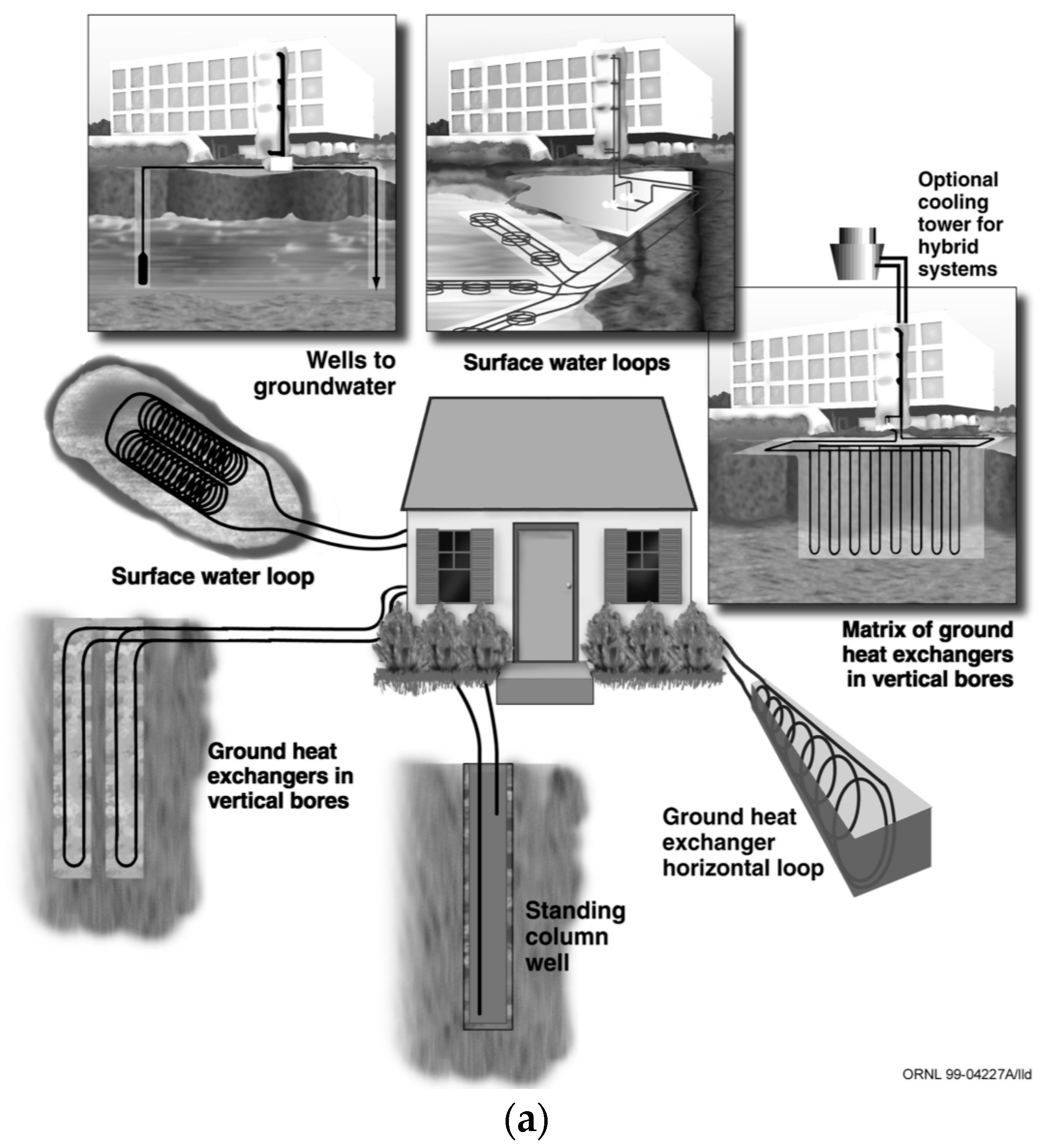
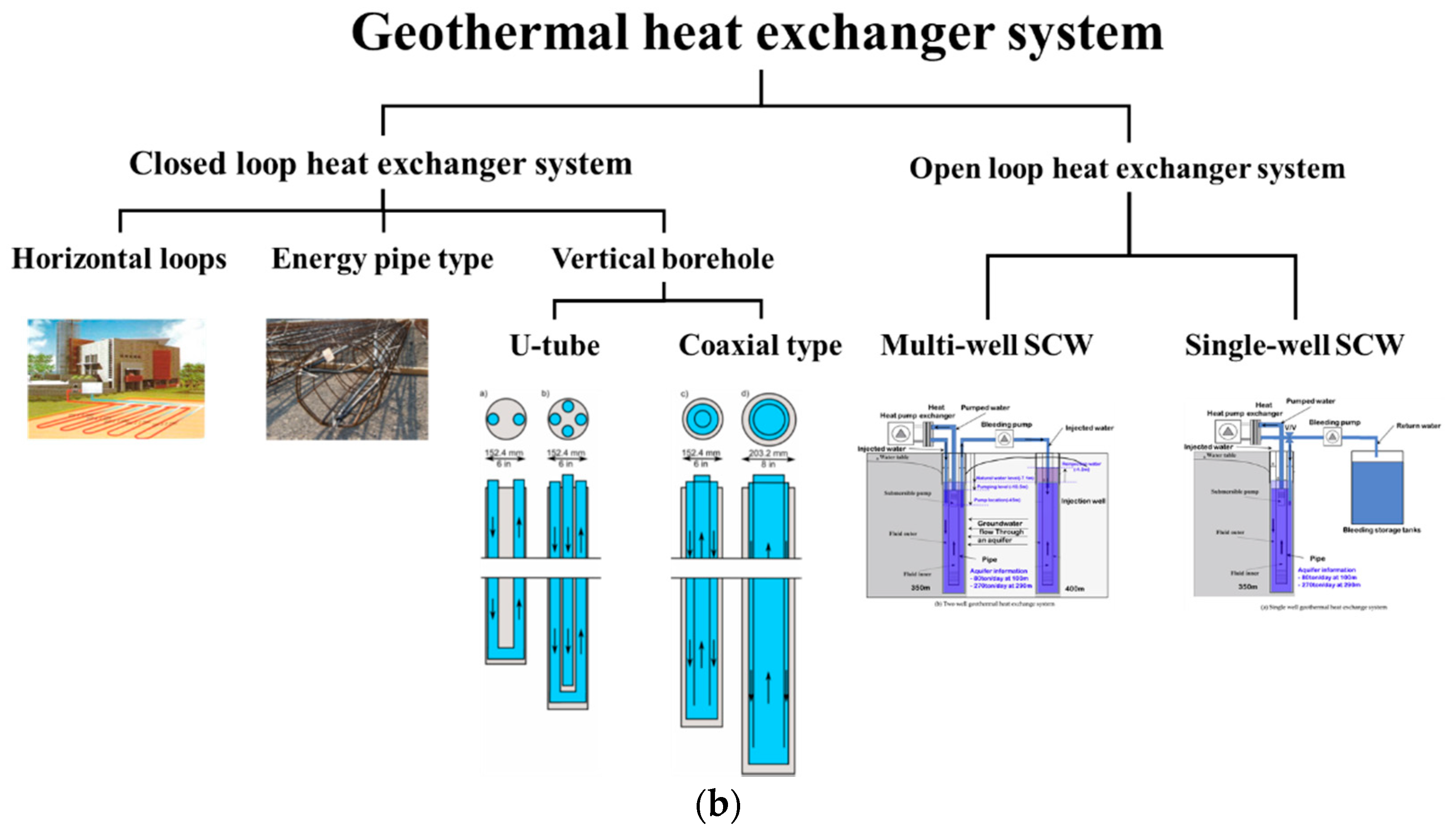
A schematic diagram of geothermal heat exchange systems is shown in Figure 1. The geothermal heat exchanger system is divided into two types: closed type and open type. The sealed heat exchanger is divided into surface water loops, wells to groundwater, and ground heat exchangers in vertical bores and horizontal loops. In addition, the open heat exchanger is divided into a single-well and a multi-well SCW system.
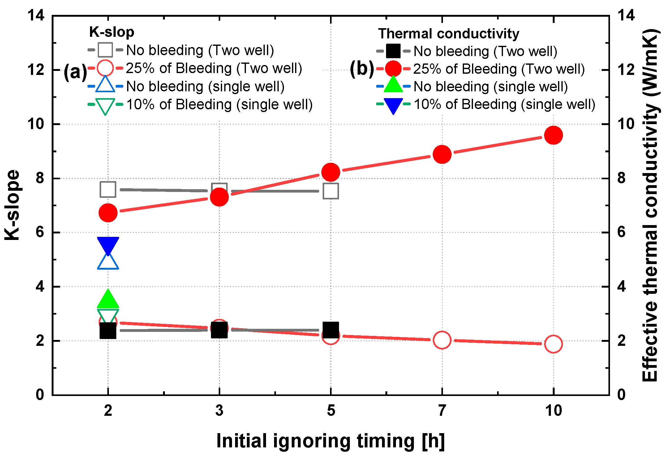
In this study, we compared, analyzed, and investigated the effective thermal conductivity of a borehole geothermal heat exchanger system and the effective thermal conductivity not applied when bleeding single-well SCWs are used. We also investigated the heat transfer characteristics during the bleeding of two-well SCWs, where water is injected from one clearing hole to the returning hole according to the bleeding rate. To compare the characteristics of closed and open heat exchangers, single- and two-well heat exchangers, for the effective thermal conductivity coefficient in the same borehole with the same depth, we intend to generate basic data on the basis and performance of geothermal heat exchanger design. The geothermal heat exchanger was characterized and the thermal performance was compared under these three conditions.

2. In Situ Thermal Response Test

Several techniques can be employed to predict the thermal conductivity of a GHEX design. The easiest approach is to use the standard value of the rock where the GHEX is located. However, this method may require expensive samples and may not provide a full profile of the field. Mogenson [8] presented a thermal response test (TRT) for estimating the ground value of underground thermal conductivity and the thermal resistance of a borehole system. The general method of TRT adopts a system in which the heat medium fluid circulates through the Hall system at a constant heat injection rate, as shown in Figure 2. The thermal response is then recorded continuously. After data acquisition, the temperature data are compared with mathematical models such as the source model [44,45,46,47,48]) or cylindrical source model [44,45,46,49,50].
Figure 3 consists of the trailer-type transport system used in this study [52,53,54,55,56]. In addition, a schematic diagram of the experimental set-up of the SCW system showing the thermal response of the test equipment shown in 
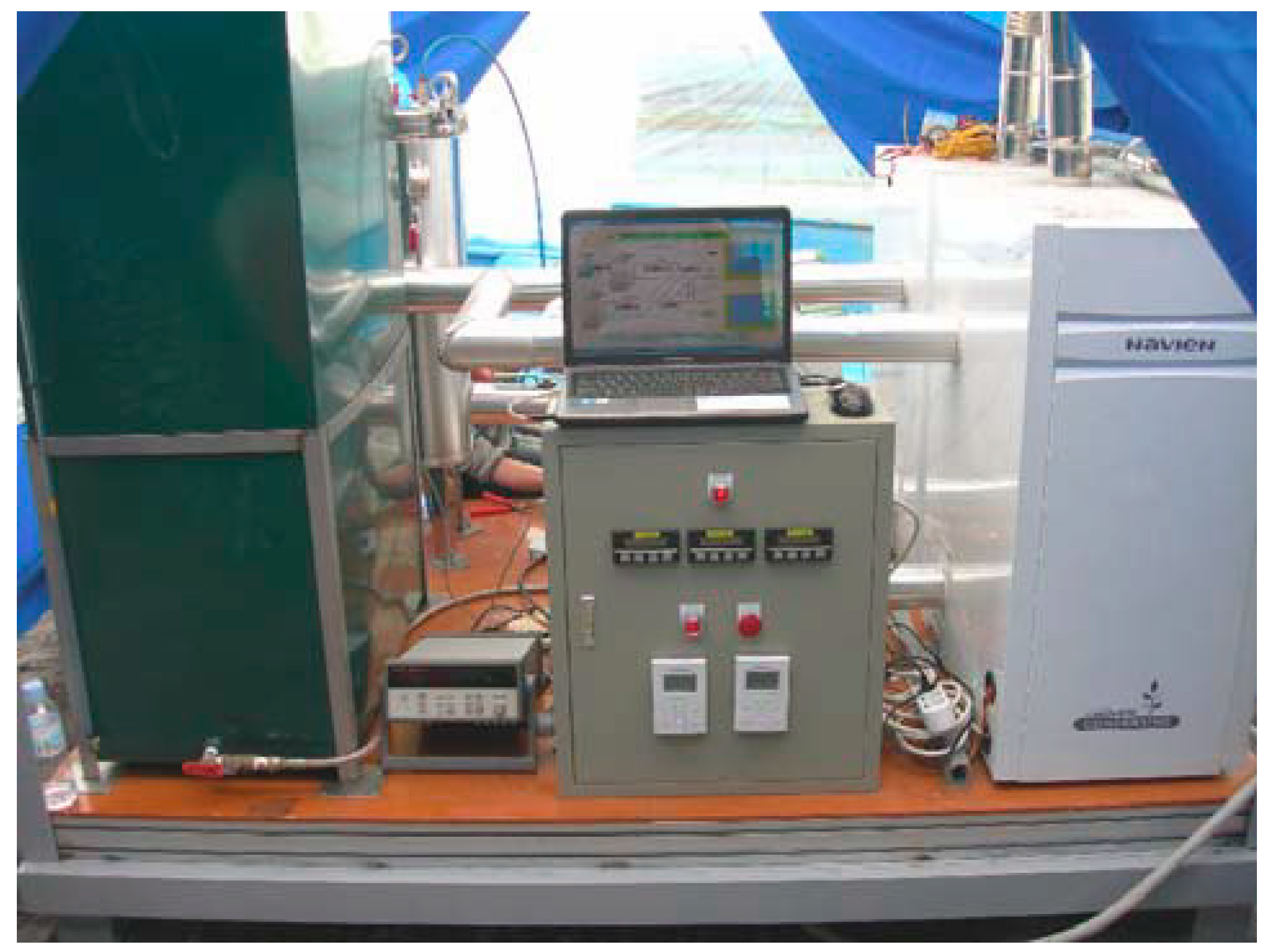
Figure 4 is shown. In the test set-up (Agilent 34970A), a measurement program (LabView) and a flow meter were used to measure temperature and flow. Control circuits and temperature sensors were installed on each pipe at the inlet/outlet, including boilers and filters. Each device used an instrument that was calibrated at the factory or regularly. The boiler capacity provided 84 kW (42 kW × 2 units) of oil condensation. The flow rate of the circulating fluid was measured using a flow meter (Macnaught). In addition, a return pipe flow meter (water meter) was installed and the bleeding rate was controlled to measure the bleeding rate of the measuring device without introducing water into the SCW system. Table 1 shows the components installed in the experimental and measurement devices used in this study.
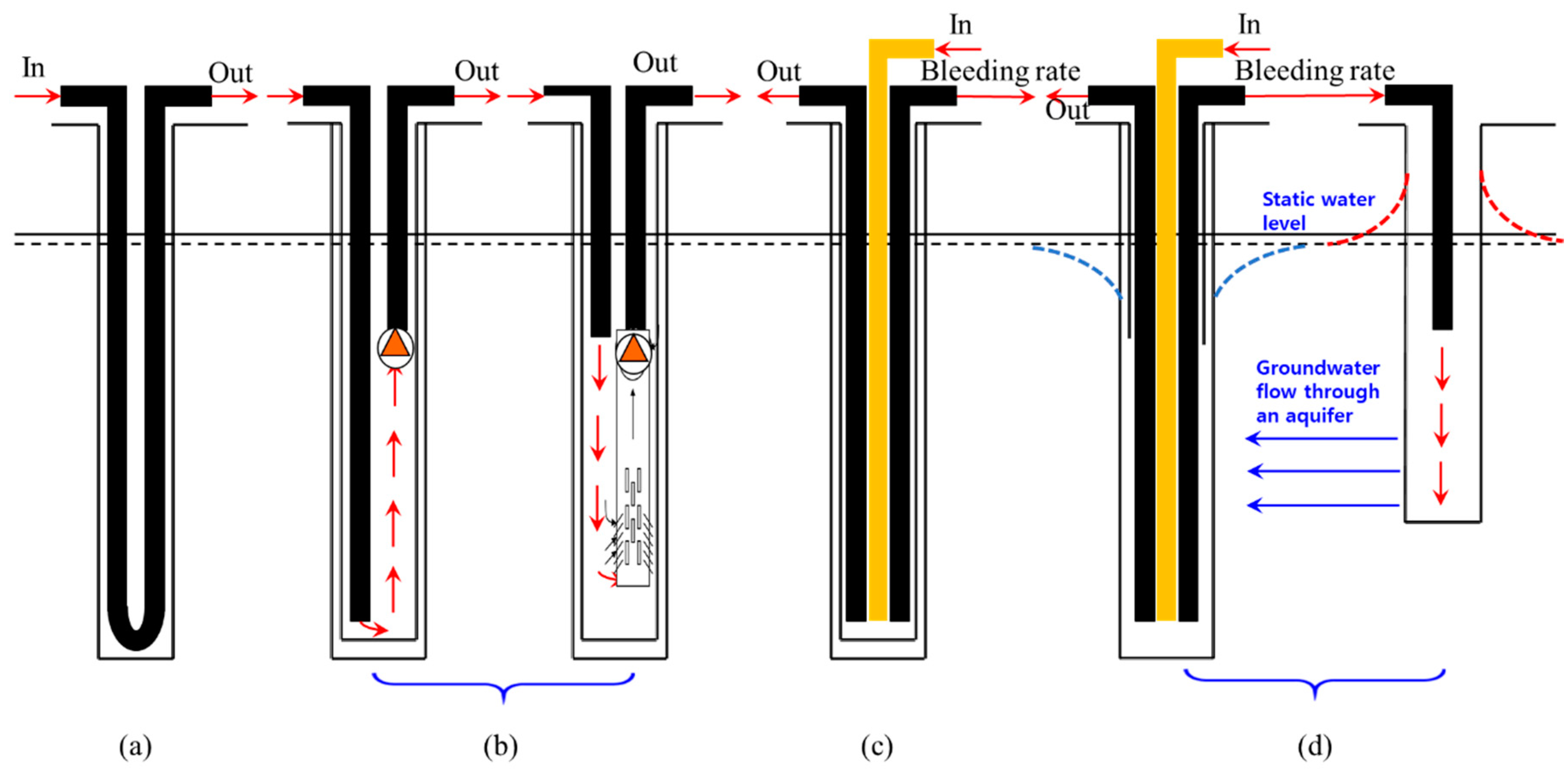
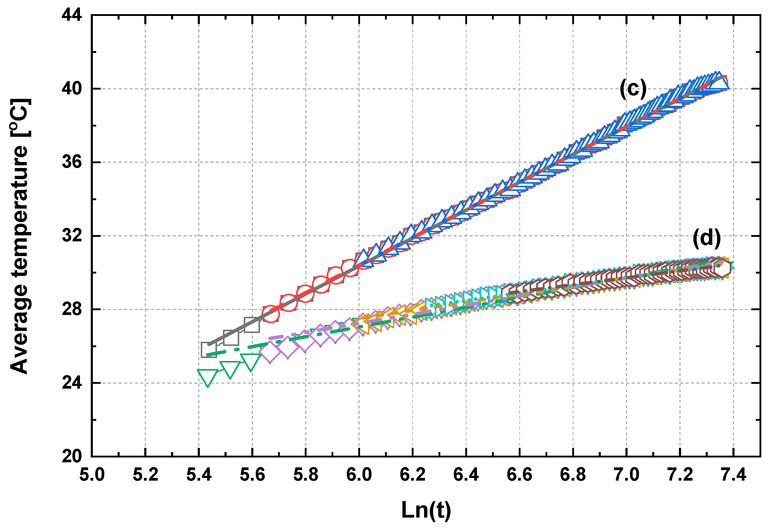
Figure 5 shows the behavior of the closed borehole and single/two-well SCW systems according to the exponential and exponential used in this study, as well as the position of the return pipe. The groundwater heat exchanger under test is of type SCW, eight inches in diameter and 350 m and 400 m deep. It has a PVC inner casing and a top extraction/bottom circulation structure. During the drilling process, water intake was observed to increase significantly at depths of 80–100 m and 270–290 m. The maximum quantity analyzed was found to be in the range of 600–800 tons/day based on the groundwater impact survey results, and the stable withdrawal capacity was found to be in the range of 200–250 tons/day. Table 2 shows the bleeding percentage used in this study. The bleeding rates of 10% and 25% have absorption capacities of 80 tons/day and 200 tons/day (0.06 m3/min and 0.13 m3/min), respectively. In this study, the characteristics of single-well and two-well underground heat exchangers were compared. We also evaluate the thermal performance of a two-well system and a single-well system underground heat exchanger when there is no discharge rate and when returning from the inlet and re-injecting the discharge into the wells [40,41,42].

3. Validation of Line-Source Theory and Uncertainty of System

3.1. Line-Source Theory

The line-source theory for calculating the thermal performance of a hermetic heat exchanger is well established, and it was applied to thermal performance testing for decades [57,58]. The theory was extended to comparisons and studies of energy losses in different heat exchanger arrangements [59,60]. In this study, the line-source theory is applied to the TRT of a closed source heat exchanger, and the performance of an open underground heat exchanger is extended to the measurement.
The equation for the temperature domain as a function of time (t) and radius (r) around the line-source model with a constant heat injection rate (Q) can be used as the approach value of heat injection from closed and open geothermal heat exchangers as follows:
T ( r ,   t ) T o = Q 4 π k H x e u d u u .
The exponential integral of Equation (1) can be approximated for a large value of a parameter (αt/r2) with the following simple relationship:
E 1 ( r 2 4 α t ) = ln ( 4 α t r 2 ) γ .
If the infinite series is used for Equation (1), the following summary is obtained:
T ( r , t ) T o = Q 4 π k H { ln 4 α t r 2 γ + r 2 4 α t ( 1 r 2 16 α t ) } ,
where γ is a Euler constant of 0.5772. The solution of the heat source to the bore hole can be applied only to r r b and the heat resistance R b can be used in the bore hole.
T f = Q 4 π k H ln ( t ) + Q 4 π k H ( ln ( 4 α r b 2 ) γ ) + Q L R b + T o .
Thus, a time-dependent fluid temperature equation can be described as shown in Equation (4).
The only variable in Equation (4) is ln t. It can be expressed by transforming constant ln t in a general linear equation as follows:
y = k x + c ,
where k = Q 4 π λ H ,   x = ln ( t ) ,   c = k ( ln 4 α r o 2 0.5772 ) + Q H R b + T o .  
Therefore, a linear equation can be obtained by plotting the borehole fluid temperature over time obtained through the heat exchanger system as a measured value, and the fluid temperature and ln t relationship as coordinates. The thermal conductivity (λ) can be determined by calculating using the slope (a) of Equation (5). The effective thermal conductivity and thermal resistance can be obtained from TRT data as given in Equations (6) and (7), respectively [45,46,47,48,49,50,51,52,53,54,55].
k = Q 4 π λ H .
Thermal conductivity (λ) can be expressed using the slope (k) calculated in Equation (5), the length of the borehole (H), and heat energy (Q). In Equation (6), k is proportional to the effective thermal conductivity, and
R b = H Q ( T f T sur ) 1 4 π λ ( ln ( t ) + ln ( 4 α r o 2 ) γ ) .

3.2. Uncertainty Utilizing Mass Heat Balance Method

A thermal balance approach was used as a verification method to confirm that it was reasonable to ensure the accuracy of the experiment on the fluid volume and temperature of the entire system as shown in Table 3. The simplest representation of the heat balance equation is
q in = V · C p · ( T out T in ) ,
where qin (W) is the calorific value obtained through the measured temperature and the flow rate of the pump. V (liters per minute, LPM) is the pump flow rate. Cp is the specific heat of water. Tin and Tout are the inlet and outlet temperatures of circulating water. The uncertainty of the temperature measurement for the temperature sensor was ±0.01 °C, and the signal conditioner of the digital display with analog signals was ±0.04 °C. The total uncertainty for temperature measurement is given in Equation (9).
Δ T = ( ± 0.01 ) in 2 + ( ± 0.04 ) in 2 + ( ± 0.01 ) out 2 + ( ± 0.04 ) out 2   ± 0.0825   .
Error = ± 0.0825   5   × 100 % = ± 1.65 % .
Using the highest error for the flowmeter taken from Table 4 of ± 2.03%, the total uncertainty in the heat balance equation was computed as
Total   Error = ( ± 0.0165 ) 2 + ( ± 0.0203 ) ^ 2 2.62 % .

4. Investigations and Discussion

4.1. Thermal Conductivity Characteristics of Various Rocks in a Closed Borehole Heat Exchanger System

Figure 6 shows the average temperature and the difference of inlet/outlet temperatures over time for alluvial deposit, gneiss, and granite rocks using a ground heat exchanger system with a borehole depth of 200 m using a closed loop borehole heat exchanger system [3,6,13,41,49,53]. The initial groundwater temperature from the three types of rock was approximately 15–16 °C, with an average temperature distribution of approximately 28–35 °C during the test period. The average temperatures obtained from the three types of rock are shown in Figure 7, linearized according to ln (t). The slope of the graph is linearized by the line-source method using means of k. The effective heat transfer coefficient can be obtained by substituting k for Equation (6). If heat quantity (Q), borehole depth (H), and slope (k) are substituted into Equation (1), effective heat transfer and slope values can be obtained as shown in Table 5. From Equation (6), it can be seen that k and λ are in a trade-off relationship with each other. The thermal performance evaluation results of the ground heat exchanger for the three types of rock show that the effective thermal conductivity ranges from 2.5 to 3.2 W/(m·K). Based on the results of this study, it is possible to grasp the thermal conductivity of daughters in the case of the same borehole depth according to the characteristics of the rock. In addition, the influence of groundwater is considered to be an influential factor on the effective thermal conductivity. In the future, the effect of groundwater flow on the effective thermal conductivity of underground heat exchangers will be studied.

4.2. Characteristics of the Effective Thermal Conductivity of SCW System at Different Locations of Return Pipe

Figure 8 and Figure 9 show the evaluation results of thermal performance by temperature for a ground heat exchanger with the return pipe positioned as shown in Figure 5b, using an SCW underground heat exchanger with a borehole depth of 400 m, as shown in References [31,32,33,34,35,36,37,38,39,40,41]. This study analyzed the characteristics of this in accordance with the effective thermal conductivity and thermal resistance as a study on the heat transfer characteristics according to a position above the submerged pump [52,56,57,60]. Through the research results of Lee et al. [4,11,41], it was found that the effective thermal conductivity and the thermal resistance were improved according to the effect of the position of the pump. The k-values obtained by the line-source method for the lower (Figure 8) and upper return pipes (Figure 9) were 4.26 and 4.56, respectively. Using Equation (6), the effective thermal conductivities of the lower (Figure 8) and upper return pipes (Figure 9) were 3.86 and 3.54 W/(m · K), respectively, using a borehole insertion depth of 400 m with injected calories of 48 kW. The results are shown in Table 6 and confirm that the performance improved by about 9% depending on the return pipe position of the circulating water. From the result of Figure 8 and Figure 9, the effective thermal conductivity increased at the lower location of the return pipe more than at the upper location. Through these results, it was judged that the technology can improve thermal performance. This can be important research data to improve the heat transfer characteristics in the same ground hole by considering the location of the submerged pump.
Figure 10 shows the thermal resistance in the SCW system [6,53,54]. Borinaga-Tervino et al.’s research [6] suggested two main objectives: (i) to determine the variability of the predicted ground thermal conductivity for the same evaluated ground, and (ii) to determine the influence of the type of grout used in the estimated borehole thermal resistance. As shown in Reference [6], the effective thermal conductivity of this system was obtained by substituting the values into Equation (6). Finally, the thermal resistance value was obtained, as shown in Figure 11. After 60 min at the initial condition, the thermal resistance value showed sudden and repetitive falling and rising before converging to a constant value. Despite the short measurement time of 12 h, the overall thermal resistance value converged to a constant. At the lower return pipe, the thermal resistance value also generally converged to a constant value. The average thermal resistance values obtained using Equation (7) at the lower return pipe and at the upper return pipe were approximately 0.0118 K/(W/m) and 0.0053 K/(W/m), respectively. It can be observed that the thermal resistance value at the lower return pipe was higher than that at the upper return pipe by more than 44.91%. Considering these results, it was found that the thermal resistance value acts as an important variable among the design factors in the standing column well-type underground heat exchanger. In this study, the effective thermal conductivity and thermal resistance values of the standing column well-type underground heat exchanger were measured by using a thermal response test device for the case where the return pipe is located at the bottom and the return pipe is located at the top. The effective thermal conductivity and thermal resistance values of the case where the return pipe is located at the bottom were increased by about 6.56% and 44.91%, respectively, compared to the case where the return pipe was located at the top.

4.3. Characteristics of Effective Thermal Conductivity of SCW System with Single- and Two-Well Types

Figure 11 shows the results of thermal performance according to the bleeding rate of groundwater using single-well and two-well SCW systems as in References [38,39,40,54,55,56]. Figure 11a,b show the thermal performance of a single-well SCW system, as shown in Figure 5c. A study on the effective thermal conductivity characteristics was carried out according to the bleeding effect in the single-well SCW system. Figure 11c,d show the thermal performance of a two-well SCW system, as shown in Figure 5d. As shown in the schematic of Figure 5d, a study was conducted to optimize heat transfer characteristics through energy circulation caused by groundwater flow by injecting the groundwater bleeding amount from one intake hole. Therefore, thermal performance improvement through effective thermal conductivity was analyzed through the thermal performance evaluation of the SCW underground heat exchanger.
From the results of Figure 11a,b, obtained through the average inlet/outlet temperature according to ln (t) using the line-source method, the k-values were 4.88 and 2.94, respectively. The effective thermal conductivity values shown in Table 7 were 3.45 and 5.59 W/(m·K). From this result, the improvement of thermal performance was improved by 62% when bleeding rate was performed. In the case of single-well SCW, the heat transfer characteristics were improved by minimizing the energy change of the groundwater because of the amount of water flowing from the underground hole into the groundwater.
Table 7 also shows the line-source method results of Figure 11c,d using two-well SCW underground heat exchangers. Finally, the thermal performance of the system improved by about four times compared to the bleeding rate. This improvement of the effective thermal conductivity was the result of the groundwater being well used as the circulating water. Figure 11d shows the characteristic that the value of k (i.e., the exact slope) changed using the IIT (initial ignoring time) method. It was confirmed that the experiments need to be carried out through a longer-term performance evaluation relative to the current measurement method, as this affects the final effective thermal conductivity. As shown in Figure 11a,b, the k value and the effective heat transfer value were almost constant. However, in the two-well SCW of Figure 11c,d, the value of k decreased with time (Figure 12). The reason for this is because the groundwater temperature uses energy without the change of the Bleeding water injected from the intake hole to the return hole. It was judged that the two-well SCW system can maximize the heat consumption in a narrow area by using a geothermal heat exchanger.
Figure 12 shows the characteristic of effective thermal conductivity under no bleeding and bleeding conditions for single- and two-well type SCW systems with respect to the influences of the key factors, including injection rate, inlet temperature, injection–production interval, and geological conditions, on the open-loop geothermal system (OLGS) performance [43].
From the results of Figure 12, the application of bleeding to the single-well SCW system showed that the effective thermal conductivity was 162% higher than that without bleeding. In addition, the two-well SCW system also showed a 400% improvement in performance when bleeding was performed. Based on the thermal performance results of the single-well and two-well SCW system, it may be advantageous to select and use an appropriate SCW. In particular, the two-well SCW system is expected to be applicable in a very efficient underground heat exchanger design if the influence of groundwater is used well.

4.4. Characteristics of Effective Thermal Conductivity of SCW System Single/Two-Well SCW System with/without Bleeding Water

Table 7 presents the results of effective thermal conductivity measurements of the closed borehole single-well SCW system and single- and two-well SCW system for each return pipe location. In these results, the position of the single-well SCW return pipe without bleeding increased by approximately 9% compared to the lower return pipe installation position. In the case of the single-well type SCW system, the effective thermal conductivity value obtained by evaluating thermal performance in bleeding and non-bleeding conditions was 1.6 times higher in the non-bleeding condition than in the 10% bleeding condition. However, as a result of evaluating the thermal performance of the geothermal heat exchanger of the two-well SCW system, the effective thermal conductivity value was evaluated as approximately four times higher with 25% bleeding than without bleeding. From these results, it was proven that high thermal performance can be obtained by improving the groundwater flow of the groundwater suction at the well drainage well.

5. Conclusions

This paper presented the effective thermal conductivity of closed boreholes and single- and two-well type SCW systems with bleeding conditions using a TRT device specially prepared for SCW system. The comparative analysis of the effective thermal conductivity was as follows:
  • The effective thermal conductivity values and thermal resistance increased by 9.03% and 44.91%, respectively, compared with those of the installed upper return pipe of the SCW system. This result indicates that the thermal resistance and conductivity values varied with the installed location of the return pipe. These results also show that the thermal resistance is an important design parameter. Hence, it can be concluded that the location of the return pipe in the SCW should be properly selected.
  • In the case of the single-well SCW system, from the results of evaluating thermal performance in the bleeding and non-bleeding state, the effective heat conductivity value of the underground heat exchanger improved 1.6 times in the 10% bleeding state compared to the bleeding-free state. However, the stain-free condition of the two-well type SCW system did not significantly affect the initial removal time, but the linear equation was changed by applying the initial removal time at 25% bleeding condition. When injecting 25% discharge into the SCW inlet, it is considered that the linear equation needs to be changed due to the influence of the groundwater flow, and it is necessary to change the stable measurement time according to the groundwater flow.
  • Finally, from the results of the thermal performance evaluation of the two-well type SCW system, the bleeding condition was improved by about four times compared to the non-bleeding condition. From these results, it was possible to achieve high thermal performance through improvement of the groundwater flow of the groundwater suction well at the drainage well.

Author Contributions

J.Y. and C.L. conceived and designed the experiments; J.Y. performed the experiments; C.L. analyzed the data; J.Y. contributed reagents/materials/analysis tools; C.L. wrote the paper. All authors have read and agreed to the published version of the manuscript.

Funding

This research received no external funding or This research was funded by [the National Research Foundation of Korea (NRF) grant funded by the Korea government (MSIT)] grant number [No. 2019R1A2C1010055] And The APC was funded by [the National Research Foundation of Korea (NRF) grant funded by the Korea government (MSIT)].

Acknowledgments

This work was supported by the National Research Foundation of Korea (NRF) grant funded by the Korea government (MSIT) (No. 2019R1A2C1010055).

Conflicts of Interest

The authors declare no conflict of interest.

References

  1. Lund, J.; Sanner, G.; Rybach, L.; Curtis, R.; Hellström, G. Geothermal (ground-source) heat pumps: A world overview. Geo-Heat Cent. Q. Bull. 2004, 25, 1–10. [Google Scholar]
  2. EPA’ Space Conditioning: The Next Frontier, Office of Air and Radiation: 430-R-93-0044 (4/93), (993); US Energy Protection Agency: Washington, DC, USA, 1993.
  3. Hellstrom, G. Borehole Heat Exchangers: State of the Art 2001; Implementing Agreement on Energy Conservation through Energy Storage: Annex 13-Design, Construction and Maintenance of UTES Wells and Boreholes; Subtask 2; International Energy Agency (IEA): Paris, France, 2002. [Google Scholar]
  4. Lee, J.Y. Current status of ground source heat pumps in Korea. Renew. Sustain. Energy Rev. 2009, 13, 1560–1568. [Google Scholar] [CrossRef]
  5. Signorelli, S.; Bassetti, S.; Pahud, D.; Kohl, T. Numerical evaluation of thermal response tests. Geothermics 2007, 36, 141–166. [Google Scholar] [CrossRef]
  6. Borinaga-Treviño, R.; Pascual-Muñoz, P.; Castro-Fresno, D.; Blanco-Fernandez, E. Borehole thermal response and thermal resistance of four different grouting materials measured with a TRT. Appl. Therm. Eng. 2013, 53, 13–20. [Google Scholar] [CrossRef]
  7. Poppei, J.; Schwarz, R.; Mattson, N.; Lalou, L.; Wagner, R.; Rohner, E. Innovative Improvements of Thermal Response Test; Project Nr. 101690; Intermediate Report; Swiss Federal Office of Energy (BFE): Ittigen, Sweden, 2006. [Google Scholar]
  8. Morgensen, P. Fluid to Duct Wall Heat Transfer in Duct System Heat Storage. In Proceedings of the International Conference on Surface Heat Storage in Theory and Practice, Stockholm, Sweden, 6–8 June 1983. [Google Scholar]
  9. Carslaw, H.S.; Jaeger, J.C. Conduction of Heat in Solids, 2nd ed.; Oxford University Press: Oxford, UK, 1959. [Google Scholar]
  10. Eklof, C.; Gehlin, S. TED—A Mobile Equipment for Thermal Response Tests. Masters’ Thesis, Lulea University of Technology, Lulea, Sweden, 1996; p. 198. [Google Scholar]
  11. Lee, S.-K.; Woo, J.-S.; Kim, D.-K. A study of determining initial ignoring time of line source model used in estimating the effective soil formation thermal conductivities. J. Energy Eng. 2008, 17, 167–174. [Google Scholar]
  12. Austin, W.A. Development of an in situ System for Measuring Ground Thermal Properties. Masters’ Thesis, Oklahoma State University, Stillwater, OK, USA, 1998. [Google Scholar]
  13. Roth, P.; Georgiev, A.; Busso, A.; Barraza, E. First in situ determination of ground and borehole thermal properties in Latin America. Renew. Energy 2004, 29, 1947–1963. [Google Scholar] [CrossRef]
  14. Gehlin, S.; Hellström, G. Comparison of four models for thermal response test evaluation. ASHRAE Trans. 2003, 109, 1–12. [Google Scholar]
  15. Hepbasli, A.; Akdemir, O.; Hancioglu, E. Experimental study of a closed loop vertical ground source heat pump system. Energy Convers. Manag. 2003, 44, 527–548. [Google Scholar] [CrossRef]
  16. Lund, J.W.; Freeston, D.K.; Boyd, T.L. Direct application of geothermal energy: 2005 worldwide review. Geothermics 2005, 34, 691–727. [Google Scholar] [CrossRef]
  17. Ozgener, O.; Hesbasli, A. Experimental investigation of the performance of a solar-assisted ground-source heat pump system for greenhouse heating. Int. J. Energy Res. 2005, 29, 217–231. [Google Scholar] [CrossRef]
  18. Rybach, L.; Bunner, M.; Gorhan, H. Swiss Geothermal Update 1995–2000. In Proceedings of the World Geothermal Congress 2000 Kyushu, Tohoku, Japan, 28 May–10 June 2000. [Google Scholar]
  19. Sanner, B.; Hellström, G.; Spitler, J.; Gehlin, S. Thermal Response Test—Current Status and World-Wide Application. In Proceedings of the World Geothermal Congress 2005, Antalya, Turkey, 24–29 April 2005. [Google Scholar]
  20. Yavuzturk, C.; Chiasson, A.D. Performance analysis of U-tube, concentric tube, and standing column well ground heat exchangers using a system simulation approach. ASHRAE Trans. 2002, 108, 925–938. [Google Scholar]
  21. Deng, Z.; Spitler, J.D.; Rees, S.J. Performance analysis of standing column well ground heat exchanger systems. ASHRAE Trans. 2006, 112, 633–643. [Google Scholar]
  22. Rees, S.J.; Spitler, J.D.; Deng, Z.; Orio, C.D.; Johnson, C.N. A study of geothermal heat pump and standing column well performance. ASHRAE Trans. 2004, 110, 3–13. [Google Scholar]
  23. Mikler, V. A Theoretical and Experimental Study of the “Energy Well” Performance. Masters’ Thesis, The Pennsylvania State University, State College, PA, USA, 1993. [Google Scholar]
  24. Oliver, J.; Braud, H. Thermal exchange to earth with concentric well pipes. Trans. ASAE 1981, 24, 906–910. [Google Scholar] [CrossRef]
  25. Yuill, G.K.; Mikler, V. Analysis of the effect of induced groundwater flow on heat transfer from a vertical open-hole concentric-tube thermal well. ASHRAE Trans. 1995, 101, 173–185. [Google Scholar]
  26. Yu, X.; Zhang, Y.; Deng, N.; Ma, H.; Dong, S. Thermal response test for ground source heat pump based on constant temperature and heat-flux methods. Appl. Therm. Eng. 2016, 93, 678–682. [Google Scholar] [CrossRef]
  27. Spitler, J.D.; Rees, S.J.; Deng, Z.; Chiasson, A.; Orio, C.D.; Johnson, C. ASHRAE RP-1119: R&D Studies Applied to Standing Column Well Design; Final Report; Oklahoma State University: Stillwater, OK, USA, 2002. [Google Scholar]
  28. Orio, C.D. Geothermal heat pumps and standing column wells. Geotherm. Resour. Counc. Trans. 1994, 18, 375–379. [Google Scholar]
  29. Orio, C.D. Design, use & example of standing column wells. In Proceedings of the IGSPHA Technical Meeting, 15–17 May 1995. [Google Scholar]
  30. Orio, C.D. Geothermal heat pump applications industrial/commercial. Energy Eng. 1999, 96, 58–66. [Google Scholar] [CrossRef]
  31. Park, Y.; Kim, N.; Lee, J.Y. Geochemical properties of groundwater affected by open loop geothermal heat pump systems in Korea. Geosci. J. 2015, 19, 515–526. [Google Scholar] [CrossRef]
  32. Orio, C.; Johnson, C.; Rees, S.; Chiasson, A.; Deng, Z.; Spitler, J. A survey of standing column well installations in North America. ASHRAE Trans. 2005, 111, 109–121. [Google Scholar]
  33. Abu-Nada, E.; Akash, B.; Al-Hinti, I.; Al-Sarkhi, A.; Nijmeh, S.; Ibrahim, A.; Shishan, A. Modeling of a geothermal standing column well. Int. J. Energy Res. 2008, 32, 306–317. [Google Scholar] [CrossRef]
  34. Deng, Z. Modeling of Standing Column Wells in Ground Source Heat Pump Systems. Ph.D. Thesis, Oklahoma State University, Stillwater, OK, USA, 2004. [Google Scholar]
  35. Ng, B.M.; Underwood, C.P.; Walker, S.L. Standing column wells e modeling the potential for applications in geothermal heating and cooling. HVAC&R Res. 2011, 17, 1089–1100. [Google Scholar]
  36. Gehlin, S. Thermal Response Test—In-Situ Measurements of Thermal Properties in Hard Rock. Ph.D. Thesis, Lulea University of Technology, Lulea, Sweden, 1998. [Google Scholar]
  37. Deng, Z.; Rees, S.; Spitler, J. A model for annual simulation of standing column well ground heat exchangers. HVAC&R Res. 2005, 11, 637–655. [Google Scholar]
  38. Nguyen, A.; Pasquier, P.; Marcotte, D. Development of an ODE model featuring a three-level bleed control and an off-loading sequence for standing column wells. In Proceedings of the BS2013, Chambery, France, 26–28 August 2013; pp. 26–28. [Google Scholar]
  39. Ramesh, A.; Spitler, J.A. Quasi-two-dimensional standing column well model for ground source heat pump systems. In Proceedings of the Innostock Conference 2012, Lleida, Spain, 16–18 May 2012. [Google Scholar]
  40. Lee, C. Thermal performance of a standing column well geothermal heat exchanger system using re-injection of bleeding water. Geothermics 2019, 82, 73–80. [Google Scholar] [CrossRef]
  41. Lee, C.; You, J.; Park, H. In-situ response test of various borehole depths and heat injection rates at standing column well geothermal heat exchanger systems. Energy Build. 2018, 172, 201–208. [Google Scholar] [CrossRef]
  42. Choe, T.G.; Ko, I.J. Method of simulation and estimation of SCW system considering hydrogeological conditions of aquifer. Energy Build. 2018, 163, 140–148. [Google Scholar] [CrossRef]
  43. Wang, G.; Song, X.; Shi, Y.; Sun, B.; Zheng, R.; Li, J.; Pei, Z.; Song, H. Numerical investigation on heat extraction performance of an open loop geothermal system in a single well. Geothermics 2019, 80, 170–184. [Google Scholar] [CrossRef]
  44. Sanner, B.; Hellstrom, G.; Spitler, J.; Gehlin, S. More than 15 years of mobile thermal response test—A summary of experiences and prospects. In Proceedings of the European Geothermal Congress, Pisa, Italy, 3–7 June 2013. [Google Scholar]
  45. Ingersoll, L.R.; Plass, H.J. Theory of the ground pipe heat source for the heat pump. Heat. Piping & Air Cond. 1948, 20, 119–122. [Google Scholar]
  46. Kavanaugh, S.P. Simulation and Experimental Verification of Vertical Ground-Coupled Heat Pump Systems. Ph.D. Thesis, Oklahoma State University, Stillwater, OK, USA, 1985. [Google Scholar]
  47. Kavanaugh, S.P.; Rafferty, K. Ground-Source Heat Pumps—Design of Geothermal Systems for Commercial and Institutional Buildings; American Society of Heating, Refrigeration and Air Conditioning Engineers (ASHRAE): Atlanta, GA, USA, 1997. [Google Scholar]
  48. Gehlin, S. Thermal Response Test: Method Development and Evaluation. Ph.D. Thesis, Luleå University of Technology, Luleå, Sweden, 2002. [Google Scholar]
  49. Cruickshanks, F.; Bardsley, J.; Williams, H.R. In-Situ Measurement of Thermal Properties of Cunard Formation in a Borehole. In Proceedings of the Terrastock 2000 Halifax, Nova Scotia, Stuttgart, Germany, 28 August–1 September 2000; pp. 171–175. [Google Scholar]
  50. Benighaus, C.; Bleicher, A. Neither risky technology nor renewable electricity: Contested frames in the development of geothermal energy in Germany. Energy Res. Soc. Sci. 2019, 47, 46–55. [Google Scholar] [CrossRef]
  51. Sanner, B.; Reuss, M.; Mands, E.; Müller, J. Thermal response test-experiences in Germany. In Proceedings of the Terrastock, Stuttgart, Germany, 28 August–1 September 2000; pp. 177–182. [Google Scholar]
  52. Spilker, E.H. Ground-coupled heat pump loop design using thermal conductivity testing and the effect of different backfill materials on vertical bore length. ASHRAE Trans. 1998, 104, 775. [Google Scholar]
  53. Marcotte, D.; Pasquier, P. On the estimation of thermal resistance in borehole thermal conductivity test. Renew. Energy. 2008, 33, 2407–2415. [Google Scholar] [CrossRef]
  54. Nguyen, A.; Pasquier, P.; Marcotte, D. Thermal resistance and capacity model for standing column wells operating under a bleed control. Renew. Energy 2016, 76, 743–756. [Google Scholar] [CrossRef]
  55. Nam, Y.; Ooka, R. Numerical simulation of ground heat and water transfer for groundwater heat pump system based on real-scale experiment. Energy Build. 2010, 42, 69–75. [Google Scholar] [CrossRef]
  56. Al-Sarkhi, A.; Abu-Nada, E.; Nijmeh, S.; Akash, B. Performance evaluation of standing column well for potential application of ground source heat pump in Jordan. Energy Convers. Manag. 2008, 49, 863–872. [Google Scholar] [CrossRef]
  57. Minea, V. Experimental investigation of the reliability of residential standing column heat pump systems without bleed in cold climates. Appl. Eng. 2013, 52, 230–243. [Google Scholar] [CrossRef]
  58. Jia, G.S.; Tao, Z.Y.; Meng, X.Z.; Ma, C.F.; Chai, J.C.; Jin, L.W. Review of effective thermal conductivity models of rock-soil for geothermal energy applications. Geothermics 2019, 77, 1–11. [Google Scholar] [CrossRef]
  59. Gehlin, S.; Hellström, G. Influence on thermal response test by groundwater flow in vertical fractures in hard rock. Renew. Energy 2003, 28, 2221–2238. [Google Scholar]
  60. Bayer, P.; Saner, D.; Bolay, S.; Rybach, L.; Blum, P. Greenhouse gas emission savings of ground source heat pump systems in Europe: A review. Renew. Sustain. Energy Rev. 2012, 16, 1256–1267. [Google Scholar] [CrossRef]
Figure 1. Schematic diagram of ground-source heat pump geothermal heat exchange systems: (a) installed examples; (b) classification of geothermal heat exchanger system.
Applsci 10 02467 g001aApplsci 10 02467 g001b
Figure 2. Thermal response test apparatus [51].
Applsci 10 02467 g002
Figure 3. Experimental apparatus of a standing column well (SCW) system.
Applsci 10 02467 g003
Figure 4. Schematic diagram of the measurement apparatus of the SCW system.
Applsci 10 02467 g004
Figure 5. Schematic diagrams of a geothermal heat exchanger system: (a) closed loop; (b) SCW with return pipe location; (c) single-well SCW with bleeding rate; (d) two-well SCW system.
Applsci 10 02467 g005
Figure 6. Average temperature distribution of various of rocks.
Applsci 10 02467 g006
Figure 7. Linearization of line-source method for various rock distributions.
Applsci 10 02467 g007
Figure 8. Linearization of the average temperature at the location of the lower return pipe.
Applsci 10 02467 g008
Figure 9. Linearization of the average temperature at the location of the upper return pipe.
Applsci 10 02467 g009
Figure 10. Resistance value at the lower and upper locations of the return pipe.
Applsci 10 02467 g010
Figure 11. Linearization of the average temperature of the single- and two-well type SCW systems: (a) single-well type (no bleeding); (b) single-well type (10% bleeding); (c) two-well type (no bleeding); (d) two-well type (25% bleeding).
Applsci 10 02467 g011aApplsci 10 02467 g011b
Figure 12. Effective thermal conductivity characteristic under no bleeding and bleeding conditions for single- and two-well type SCW systems: (a) k-slope; (b) effective thermal conductivity.
Applsci 10 02467 g012
Table 1. Specifications of the thermal response test rig.
No.ItemsManufacturerSpecificationRemarks
1BoilersKyungdong35,300–36,500 kcal/h-
2Sand filterFeelanTek400 L/min-
3PumpsWillo8 m3/h-
4Oil tank-400 L-
5Flow meter (water)Blue-White20–200 L/min±1%
6Flow meter (oil)Macnaught35–830 cc/min±1%
7Temperature sensor Pt100 Ω, four-wire±0.5%
8Data loggerAGILENT34,790 A, 34902MUX±1%
9InverterLSSV015iG5A, 380 V, 30–60 Hz-
10Measurement programNational InstrumentsLabView 8.6-
Table 2. Experimental conditions of bleeding rate for SCW system.
No.Bleeding ConditionsWater Withdrawal Capacity (m3/day)Remarks
1No bleeding rate0
210% bleeding rate800.06 m3/min
325% bleeding rate2000.13 m3/min
Table 3. Heat balance check.
LocationTransducer Reading (W)Average q (W)Difference (W)% of Average Power
A2506.62657.8101.23.88
B3207.23302.593.32.82
Table 4. Results from the flowmeter calibration.
Actual Flow (LPM)Calibration Flow (LPM)Error (%)
3.3163.2920.73
15.8716.0321.01
100.9102.992.03
350.62355.411.35
Table 5. Evaluation of effective thermal conductivity and experimental conditions at borehole depth of 200 m in various rocks.
UnitAlluvium #1Alluvium #2Gneiss #1Granite #1Granite #1Granite #2
Initial temperature°C15.215.416.21614.516.3
Average temperature°C28.5313133.228.430.1
Heat injectionkW14.513.913.81414.114,0
Slope (K)-2.1512.1751.5842.0941.9452.094
Effective thermal conductivityW/(m·K)2.6142.6633.2132.6482.8132.518
Table 6. Results of effective conductivity calculation.
TypeUnitSingle SCW (Lower Location of Pump)Single SCW (Upper Location of Pump)
Initial temperature°C15.2716.13
Average temperature°C34.4532.44
Heat injectionkW4848
Slope (K)-4.1464.545
Effective thermal conductivityW/m·K3.863.54
Ratio of bleeding rate to no bleeding%109-
Table 7. Comparison on the measuring of thermal conductivity in various bleeding conditions.
TypeUnitSingle SCW (No Bleeding)Single SCW (10% Bleeding)Two-Well SCW (No Bleeding)Two-Well SCW (25% Bleeding)
Initial temperature°C16.1316.1317.2515.64
Average temperature°C34.4532.4440.9230.91
Heat injectionkW40407881
Slope (K)-2.9372.9377.5251.88
Effective thermal conductivityW/m·K3.455.592.49.59
Ratio of bleeding to no bleeding%-162-400

