Article

HBIM as Support of Preventive Conservation Actions in Heritage Architecture. Experience of the Renaissance Quadrant Façade of the Cathedral of Seville

by
Roque Angulo-Fornos
* and
Manuel Castellano-Román
Department of Graphic and Architectural Expression, University of Seville, 41012 Seville, Spain
*
Author to whom correspondence should be addressed.
Appl. Sci. 2020, 10(7), 2428; https://doi.org/10.3390/app10072428
Submission received: 21 January 2020 / Revised: 20 March 2020 / Accepted: 30 March 2020 / Published: 2 April 2020
(This article belongs to the Special Issue BIM and HBIM: Standardisation and interoperability)

Abstract

:

Featured Application

HBIM models generation for managing heritage information, oriented to preventive conservation of assets of cultural interest.

Abstract

This paper discusses the generation of Historic Building Information Models (HBIM) for the management of heritage information aimed at the preventive conservation of assets of cultural interest, through its experimentation in a specific case study: the façade of the Renaissance quadrant of the Cathedral of Seville. Two methodological aspects are presented: On the one hand, the process of modeling the solid entities that compose the digital model of the object of study, based on the semi-automatic estimation of the generating surfaces of the main faces; on the other hand, a methodological proposal for the modeling of information on the surface of the model. A series of images and data tables are shown as a result of the application of these methods. These represent the process of introducing information related to the current conservation status documentation and recording the treatments included in the preventive conservation works recently developed by a specialized company. The implementation of the digital model in the exposed work validates it as a solvency option, provided from the infographic medium, when facing the need to contain, manage and visualize all the information generated in preventive conservation actions on heritage architecture, facilitating, in turn, cross-cutting relationships between the different analysis that result in a deeper knowledge of this type of building.

1. Introduction

This article discusses the generation of an Historic Building Information Model (HBIM) aimed at the preventive conservation of the Renaissance quadrant façade of the Cathedral of Seville. The HBIM model is designed to support knowledge, management and intervention actions on architectural heritage, which are the bases of preventive conservation. Specifically, this work focuses on high accuracy three-dimensional models integrating HBIM models. In this sense, this article develops a number of methodological strategies which have produced interesting results. These strategies are the evolution of the methods followed in previous works, such as those published in [1,2,3,4,5,6].
Within the general problem faced by the development of HBIM models (always referring to knowledge, management and intervention in architectural heritage), this work focuses on the resolution of two very specific aspects related to the intervention in heritage buildings. The first is the need of having an exhaustive graphic control of the current state of the building in order to adequately support any type of decision. Additionally, this aspect affects the resolution of another pressing problem in heritage documentation: duplicity and loss of information. Funds allocated for the acquisition of graphic surveys are often associated with single intervention impulses. This information ends up dispersed or misfiled, avoiding its proper use in future conservation actions. The unification of all the information, including that related to accurate surveys, in a single container is essential. To achieve this, the HBIM model must accurately present the reality of the building. In recent years, many publications have made interesting contributions focused on solving the difficulties involved in this problem. This research deals with an extensive state of the question related to this topic in Section 2.1, referring to the transformation of the graphic information captured from the heritage object (by laser scanner or photogrammetry) into HBIM models. In that sense, this work provides a novel methodology in some aspects, such as the use of reverse engineering applications or innovation in the modeling process of solid entities in CAD software that are later integrated in the HBIM model.
On the other hand, focusing the discourse on preventive conservation actions, HBIM models face the need to register and systematize information related to various states of the heritage building. It is necessary to record in detail the state of the building prior to any intervention on it, as well as all the information related to the actions executed in those processes. In general, this is information about building damages and the treatments used to eliminate or alleviate them, which are difficult to model in HBIM. Even more difficult is the modeling of surface damages, such as humidity, erosion or chemical transformations of the material.
Despite the great development of HBIM in recent years, few scientific contributions have focused on these issues [7,8,9,10,11]. Two strategies can be recognized in them. The first option involves the subdivision of the model into multiple fragments to contain the information about the damages. Conflicts emerge when the damages subdivision does not fit with other subdivisions which attend to historical chronology or constructive analysis. The second option is the overlay of surface entities on the model which contain the information about the damages. This second option is usually invalidated by the modeling difficulty in complex heritage buildings. To overcome those difficulties, this research proposes an innovative solution: Modeling a new type of entity, which is easy to generate and manipulate, and capable of containing the necessary information independently from solid entities and over any type of geometry.
In reference to the case study, the graphic entities of the model have information adapted to the work routine used by the company responsible for the preventive conservation of the facades of the Cathedral of Seville. Thus, the work described and discussed in this research has consisted of modeling a fragment of the façade of the Renaissance quadrant of the temple for the generation of an HBIM model that allows the management of the information attached related to its preventive conservation. Specifically, the work has focused on the façade section that adjoins the atrium of San Cristóbal, which was restored in 2017. Once this work was completed, the results were considered by the members of the conservation company team based on their feasibility, usefulness and relevance to be applied to other future cases.

Case Study

The so-called Renaissance quadrant of the Cathedral of Seville is a set of spaces that house the Sacristies and the Sacrum Senatum of its Chapter (Figure 1). Under the denomination of Sacristies, the spaces dedicated to the preparation for the liturgy include: Oratory, Wardrobe, Lavatories, Treasure rooms and Sacristans’ rooms [12]. In the case of the Sacrum Senatum, the Chapter Hall, Antecabildo, accounting offices, restrooms, courtyards and other auxiliary facilities [13] are included. This set is the result of a long process of projects, reforms and transformations, hidden behind an imposing wall that gives it the appearance of a unitary whole. Contained between this wall and the southeast façade of the cathedral, a group of heterogeneous buildings were constructed, one after the other, until the available space was filled. In turn, these constructions were progressively amortizing the old defensive structures that separated the previous Mosque, and later the Gothic cathedral, from the Alcazar [14]. The construction of this wall and the dependencies enclosed took place between 1528 and 1596, the year in which the dome of the Chapter Hall was closed and the accounting offices were built on the east side of the temple. The construction started at the opposite end, on its west façade, after demolishing the previous buildings and lifting the foundations of the complex [15]. Although not all the buildings attached to the temple by its southeast façade were demolished, as part of the walls of the sacristy that Alonso Rodríguez built after closing the dome in 1506 were taken advantage of, unfinished after the unfortunate fall of that structure in 1511. These remains will be the starting point of the building of the complex, which began with the elevation of the perimeter wall attached to the old sacristy and to the south front of the cathedral’s transept.
The project and construction of these Chapter facilities have been analyzed in detail in several monographs, which show the great complexity of the process [13,16,17,18,19,20,21,22,23,24], resulting in the so-called Renaissance quadrant or Chapter rooms, depending on the researchers. It has been widely recognized as a masterpiece of the Hispanic Renaissance and has had an enormous influence on many buildings promoted by the Archbishopric of Seville and in the rest of Andalusia [12,22,25]. Its architectonical solutions were widely repeated, giving rise to the so-called Sevillian school or production center, of great importance in the Hispanic scenario [21] (pp. 160–161), [26] (pp. 48–55), [27] (pp. 192–194).

2. Materials and Methods

The research has developed the generation of a digital model of the case study and a database linked to it. It also includes a working protocol which would enable a company responsible for preventive conservation to dump data and to obtain reports and graphical visualizations. The essential aspects of the workflow are common to the methodological script of previous experiences and can be summarized as follows:
  • Georeferencing of the façade fragment as a part of the Cathedral. Definition of a spatial reference system and a common vocabulary for this element.
  • Photogrammetric survey of the façade fragment.
  • Three-dimensional modeling of the façade fragment.
  • Data structure required by the conservation company.
  • Generation of the HBIM model.
  • Data entry to graphic entities.
  • Start-up and evaluation of results.
  • Definition of systematized and standardized input and output information protocols.
Within this scheme, phases (3) and (5) include notable methodological developments regarding previous experiences and in relation to the current landscape in this field of research. This article aims to focus on these developments through its detailed description throughout this text.

2.1. Three-Dimensional Modeling: Nature of Digital Capture Data and Its Transformation

The drawing generated from any type of digital capture, including the point cloud generated by laser scanning or photogrammetric processing, should be preceded by prior knowledge of the building through direct contact with it. Therefore, the prior, parallel and subsequent analysis that leads to continuous object-drawing feedback is considered. Starting from this premise, the next step is to describe the digital capture phase, the second point (after the proper georeferencing process) of the architectural survey process following the methodological scheme described.
The final objective of the survey will condition the general approach, which will be very different if it is only a first approach to the building (for which the methods of direct survey would be perfectly valid), or if it is a morphological and metric exhaustive knowledge (for which one would have to resort to topographic or photogrammetric techniques). In any case, the characteristics of the object (dimensions, formal complexity, conservation status, etc.) will also influence the strategy.
In this case it is assumed that the scope of the objectives set in this investigation necessarily implies the generation of a three-dimensional digital model of the object of study. In addition, a maximum strategy is chosen to support actions that are as general and transversal as possible in relation to knowledge (in all possible aspects), building analysis and management. Therefore, the specific purpose of the capture would be to exhaustively generate the necessary information to confidently face the integral three-dimensional modeling of the object. Exhaustiveness is understood as metric and formal accuracy, and as a level of material complexity. That is, the model has to present geometric deformations of the object that leave the possible theoretical design, whether due to structural damages or defective execution processes, as well as formal and superficial alterations due to the passage of time (such as significant material losses or stains due to moisture or atmospheric agents). Therefore, the information captured should be the maximum that current methods allow us to obtain in relation to their geometric and formal configuration, as well as their physical attributes. This decision is justified by the need that the resulting model can convey with solvency the development of described actions on objects of high complexity, which is unattainable if it is not from transversality, rigor and accuracy. The model should be accurate enough to allow graphics to be generated with the rigor and detail required by an architectural heritage intervention project. These requirements are only achievable today starting from massive capture techniques such as laser scanner or digital photogrammetry based on structure from motion (SFM), whose results are three-dimensional clouds of points.
On the other hand, the need to solve the problems of duplication and loss of information (so common in the field of knowledge of heritage architecture), would invalidate any strategy that implies the coexistence, without any link, of various models with different levels of accuracy or containers of different plots of information. That is why it was decided to develop a single model of information for each object of study, which does not prevent also including different levels of detail or information that produce different graphic images or different alphanumeric transfers.
Once the capture method is finalized, it is necessary to consider the methodology for converting the captured data into solid entities capable of generating information (morphological or geometric, metric, physical and other), in addition to be able to contain information provided externally. A review of this field implies the consideration of various methods already defined and classified in a primary way by [28] in what it is called “as-built” building information modeling (BIM) approaches, or more recently updated in [29] (pp. 394–396) through the definition of so-called grade of generation (GOG). Following these references, it has been made a first classification based on the type of geometric genesis of the graphic entities generated, distinguishing between “parametric” and “non-parametric” generation methods. The first can be defined as those in which the genesis of the various entities that make up the model responds to a series of operations that produces a three-dimensional geometry controlled by a small number of parameters. The value of each of those parameters for each entity suppose, in turn, the origin of the information provided by the model itself, and allow the variability or edition of its geometry at any time. Depending on the degree of automatism used in the modeling of the parametric entities, several parametric modeling methods have been defined:
  • Manual. It implies the manipulation of the captured data through classification, hierarchical organization and simplification processes that allow obtaining the necessary references to proceed with a manual modeling of these entities through the appropriate CAD or BIM software. It explains a previous analysis for the simplification of the starting data, since the complexity of the graphic entities generated must be reduced in order to use the modeling tools offered by such programs. This implies rejecting certain irregularities, deformations or defects of the real elements. This method is followed by most of the experiences in this field carried out so far, among which are [30,31,32,33,34,35,36,37,38,39,40], in addition to author’s works published in [1,2,3].
  • Semi-automatic by NURBs. It consists of manual or automatic tracing, on the reference of the data obtained by massive capture, of curves or surfaces based on the mathematical model non-uniform rational B-Spline (NURBs). These, submitted to various manual manipulations, derive parametric three-dimensional entities (if generated in CAD software) or parametric entities (if generated directly in BIM software) capable of being part of the information model. In this case the number of parameters used will be smaller, since much of the geometric control is subject to the NURB curve or surface. This method cannot be exempt from the necessary previous reflection on the possibilities of discretization of the entities generated. The work published in [3,41,42,43,44,45] follows this procedure.
  • Semi-automatic through parts. Method consisting of the generation of the shape from the semi-automatic adaptation of the position and rotation of parametric graphic entities directly to the point cloud for the modeling of complete construction systems from the pieces that make them up [10,46].
  • Automatic. It implies the fully automated generation of BIM parametric entities from the implementation of a series of algorithms capable of segmenting, hierarchizing and recognizing geometries in the captured data (usually dense point clouds). These mechanisms are still little explored, limiting the experiments carried out based on simple geometries (based on plans) typical of contemporary architecture of rational design [47,48,49]. There is research dedicated to the development of methods that, based on the automatic processing of point clouds, are capable of recognizing and describing more or less complex geometries (from straight lines to quadric surfaces) using reverse engineering technologies [50,51,52,53,54]. These experiences, even outside the field of research that this work occupies, can be of great applicability in the development of methodologies focused on both parametric and non-parametric modeling.
On the other hand, included in the group of non-parametric modeling can be those methods in which the final geometry of the resulting entities is not subject to the variability of a series of parameters. These methods are focused to the generation of graphic models of great accuracy and formal similarity to the real architectural object, formed by solid entities of geometry complex enough to be able to produce final graphics of great accuracy and detail. Therefore, they are models lacking the necessary simplification that would involve the parameterization of their geometry, being able to represent material and structural damages (of great utility in processes of intervention and maintenance). As in the previous group, depending on the degree of automatism used in the modeling of the entities that make up the model, several non-parametric modeling methods are defined:
  • Manual. It consists of the manipulation of the captured data through classification and ranking processes. It includes the intentional generation of curves and surfaces (adapted to the modeling method), so that they allow obtaining the necessary references to proceed to a manual modeling of the entities that make up the three-dimensional model, using the appropriate CAD software. Subsequently, these entities (generally they must be solids or closed poly-surfaces) are imported into the BIM platform for their treatment in matters of visualization and associated information. It should be noted in this group the works [1,4,55].
  • Semi-automatic. The procedure generally involves the conversion of a point cloud captured by massive capture of data techniques into a triangle mesh, whose manipulation with the appropriate software allows the modeling of CAD entities exportable to a BIM environment. This method is used by works such as those published in [56,57].
Given the initial objectives set and the nature of the object of study, the latter method (semi-automatic non-parametric modeling) was chosen for the experience developed on the west façade of the Renaissance quadrant of the Cathedral of Seville. The results of its implementation are set forth below.

2.2. Three-Dimensional Modeling: BIM Graphic Entity Management

BIM, in the field of architecture analysis, could take the nuance (which Geographic Information System (GIS) already has at urban and territorial level) of a tool capable of transferring classified or filtered information in the form of images that provide new visions or approaches able to inducing new analysis and producing new knowledge. These would offer new tools with which to translate realities as complex as the temporary transformation of historical architecture, a challenge that is always very difficult to achieve with classical methods based on the isolated observation of different types of records and documents.
In that sense, at the practical level, the proposed methodology advocates the consideration of the information model as a container of interrelated graphic entities in a hierarchical or systematized way, capable in turn of producing and containing information linked to editable databases in non-graphic environments. This consideration would make the development of the model viable in any platform, software or set of digital applications that will guarantee the correct generation, manipulation and visualization of said entities and their relationships. In general, in the academic field, the choice of BIM technology for this field of research has to do with the maturity demonstrated in the application of such requirements in the field of the Architecture, Engineering and Construction Industry (AEC).
Conditions have been established at the beginning of this text that are summarized in formal and metric precision of the entities that make up the HBIM model, and the integrity and rigor of the information they support. Therefore, given the situation of having to choose a specific BIM software to generate the model, it could be concluded that the ideal would be to work with one that allows more ease when modeling, on the one hand, and when obtaining information (themed or alphanumeric graph), on the other. The modeling of graphic entities in BIM commercial applications is based on parameterization as a generation and control tool, which necessarily implies a certain geometric and formal simplification. This simplification facilitates subsequent transformations linked to architectural ideation processes that require the memorization of their traceability, but usually invalidates the use of these parametric tools in accurate modeling of historical architecture due to their formal complexity.
However, in this type of architecture, the original construction elements will not undergo significant formal modifications due to decisions related to possible interventions. In the face of its modeling, the path followed to arrive at its geometry (or traceability) using a type of parametric object designed specifically for a specific construction element (e.g., a wall, generally based on a parametrized parallelepiped) is not relevant. Thus, the modeling of elements through the use of generic, non-parametric solids, to which the appropriate category is subsequently associated, seems like a perfectly viable and very adequate procedure based on the requirements.
This last statement leads to a methodological proposal that, although it is not new in its approach (it has already been partially used in previous work [1,4]), has a greater potential for application in this field. That is thanks to the implementation of technologies such as reverse engineering, novel in our field of study, but widespread in other disciplines. Thus, it is proposed to make the modeling process independent of the HBIM model creation and management process at the software level, where the first of these uses an application or group of applications that facilitates the transformation of the data of any type of digital capture into three-dimensional entities complex enough to generate, once imported into the BIM platform, an accurate and rigorous information model. In that sense, it is necessary to point out that the purpose is to generate an HBIM model understood as a live drawing of the building, continuously fed back with information about the object, but it will not be, in any case, a substitution of reality; it will always be an abstraction based on the partial recording and capture of a reality of undeniable complexity.

2.3. HBIM Model Structure

An essential aspect of the information model generation strategy is the way in which its components or graphic entities are related. Decisions about the nature of these entities should be as equally important as those that define their relationships and, therefore, the configuration of the model structure.
Theoretical guidelines on models in general, and on conceptual models in particular, have been followed. These are already rooted in the scientific field and superbly synthesized by [58]. Thus, the proposed theoretical model, like any model in general, responds to three basic principles: It represents a scope of reality, simplifies it and allows us to reflect on that representation to obtain conclusions that can be applied to the knowledge of that reality. This model is considered conceptual since it is composed of the authors’ own concepts, products of their experience, or shared within the research group. On the other hand, it responds to a process of simplification of reality based on the selection of those aspects that are considered relevant based on a specific intentionality towards the field of study and a previous experience acquired regarding the nature and value of the real object. In a way, the structure of the conceptual model is describing the knowledge about reality itself. The simplification produced by the model facilitates its transmission or communication to other receivers or agents involved by converting concepts into information.
This conversion or translation is done in this case by building information modeling (BIM), moving from the theoretical conceptual model to a digital information model through proper coding. Thus, in order for this conceptual model to carry out its mission, it is necessary that it initially complies with two basic premises: That the reality it represents is discretized in different entities, and that these are categorized according to a certain intentionality within the area of knowledge to which our work it is attached. Categorization is nothing other than the establishment of relationships between the different entities that make up the model. In this way, the proposed category scheme arises from the very nature of architecture, adopting a stratigraphic structure composed of three main layers or categories: spatial, liminal and material [3] (pp. 412–413). In that way, the scheme ranges from the immateriality of spaces, containers of other objects (such as movable property) and carriers of information related to functional, environmental and design aspects or genesis, to the material strata that, generally composed of constructive elements, contain data on their materiality or information about their timeline, obtained from historiographic and archaeological studies. This step is produced through a very thin liminal layer that can contain any surface-type information, measurable or not, such as that related to the state of preservation or the nature of the patina of the wall.
Once the conceptual model has been defined, its coding in an HBIM model necessarily involves defining a strategy that conveniently translates the definition of its entities and categories into the organizational system or model structure on which the BIM software used is based.
In this case, for the work carried out in this area, the Autodesk® Revit® application was chosen due to educational license accessibility, graphic versatility and general use in our geographical area. As mentioned above, in general, any other BIM application would have successfully supported this methodological process of translating the method into its specific tools. Due to time constraints and operability, the process has been tested only in one commercial software package. This application bases the organizational scheme of its workflow, and the structure of the information model itself, on the establishment of two global groups of categories of families of entities with various utilities: model categories and annotation categories. The first encompasses all the components of the different construction systems and facilities that make up a building. Among these, the categories of space and room stand out, as the only possible options for the immaterial stratum defined in the conceptual model.
The insertion of all categories in the model is governed by a hierarchical system of relationships that determines the way in which parameters intervene in the control of information and the geometric and formal behavior of the model. Thus, each category is a container of a series of diversified families, in turn, in one or several types, and each entity that forms the model or its structure of visualization and documentation is an instance of one of those types. Then, in a BIM or HBIM model, one or more copies of each type of family employed will coexist, so that the former will be governed by parameters of instance, which condition or define properties of each entity individually, and the latter by parameters of type, which condition or define properties of all copies belonging to the same type.
Additionally, the use of the model categories for the construction of the virtual building involves the implementation of a powerful system of links between the different entities that comprise it, so that the so-called system families are usually hosts of the insertion families, establishing continuous membership or reference relationships easily presented in thematic tables or views. The former, in turn, are linked to specimens of family categories of geometric control and positioning, such as levels and grids.
On the other hand, the general theory of systems (deeply embedded in our methodological development) states that the characteristics of any system cannot be satisfactorily described through its separate elements. This premise directly affects the approach developed when coding the conceptual model described above in the form of an HBIM model. A matrix system of relationships has been proposed depending on the scale on which the problem is addressed (Figure 2). Starting from the urban or territorial scale, managed by a GIS model (not developed in this work), it gives way to a first level of architectural scale called a federated model that, conveniently georeferenced, is a binder of partial models defined by characteristics related to historical, spatial or functional aspects. Both the federated model and the partial models that constitute it are substantiated as projects in the BIM platform, and are capable of sustaining complex information structures that, linked to knowledge and management processes, can give rise to actions of effective protection of the heritage they represent (in the line of works previously developed [2,5]).
Each partial project of the building is constructed as a set of family type instances of those categories provided by Revit® that best adapt, by their characteristics, to the systems that constitute the reality of the object represented. In that sense, it is necessary to classify each of the constructive and structural systems through an exhaustive taxonomy, which requires basing the work on a sufficiently broad lexicological knowledge of the architecture. The problem arises in the lack of contemporary terminology of some elements between the categories of BIM software (whose genesis is directed to contemporary architecture). That makes it necessary to include elements within generic categories or create subcategories within existing ones for which to adapt the necessary family types.

2.4. Information Structure

This section is presented at the end of this chapter on methods for reasons related to the clarity of the speech. However, many of the aspects discussed in it should be addressed from the beginning of the process, in the reflections aimed at specifying the method to follow in the generation of the information model. In that sense, it is important to consider the information and its structure from the beginning of the process, even though, as mentioned in previous sections, the information cannot yet be considered as such, but as a set of concepts within the theoretical conceptual model. This consideration will have a decisive influence on the decisions related to the structuring of the information model and its relation to the database (or databases) to which it is linked.
The structure of the information associated with the model has been oriented towards its preventive conservation. In this way, based on the available documentation and the information provided by the company in charge of the preventive conservation of the façades of the cathedral, an information structuring strategy in four main areas of work was prepared at the beginning of the process:
  • Architectural elements and sectors. Conceptual identification of the graphic entities of the model.
  • Time factor. Processes. Conceptual identification of links of a chronological nature.
  • Injuries and treatments. Identification of concepts related to preventive conservation associated with model entities (information provided by the company).
  • Database. Relationship structure of the database linked to the model.
The effective introduction of the different concepts of the information structure in the model was carried out by creating custom parameters linked to them within the BIM software. These parameters were included in a list called shared parameters registered in a text file that can be linked to any other partial or federated project. The required parameters were assigned based on three levels of development contained in the HBIM model, two based on the complete solid entity, on two levels of detail, and another based on the exploded entities. These levels of development can be considered, for the purposes of the patrimonial use of BIM, as Levels of Knowledge (LOK) [5] (pp. 6–7).
In this way, the entity constituted by complete volumetric models (instance of wall category) has associated parameters that refer to the element as a whole: Identification, basic patrimonial information on stylistic ascription and principal authorship, legal protection figures that affect it, record of interventions and related dissemination actions. Regardless of its graphic detail (which has become high level due to representation needs), it is assigned to a level of knowledge LOK300 according to the classification established in [5] (pp. 6–7). In the case of the exploded model of the façade, each piece is an object of registration and, therefore, parameters related to a higher level of knowledge can be associated. Each piece is assigned a unique identifier and is characterized with identification parameters, injuries, treatments and actions. Therefore, it is ascribed to a level of knowledge LOK500 according to the classification established in [5] (pp. 6–7).
The values defined in the previous paragraph refer to one LOK per item. Following the criteria adopted by the working group, it is mandatory to assign a global LOK to both partial and federated models. In this case, the level of knowledge assigned to the partial model that contains the façade fragment is LOK200 based on the current development status. In the case of the federated temple model, since the current level of development consists of a basic volumetric model with the only insertion of a partial model (the one that concerns us in this experience), it is assigned to LOK100.

3. Results

The results obtained from the application of the methods presented in the case study are presented below.

3.1. Three-Dimensional Modeling

The workflow developed for three-dimensional modeling started from a massive capture of data using photogrammetric techniques whose result consisted of a dense cloud of points. This contains data of the points corresponding to their position, color and orientation (coordinates X, Y and Z, color (RGB) and normal Nx, Ny and Nz). Some metric and quantitative details about the photogrammetric survey are reported below:
• Number of control points (topographic survey): 8.
• Number of photographic shots: 150.
• Camera: Canon SLR camera, model EOS 1000D.
• Photogrammetric technique: SFM (Structure from Motion).
• Cloud size: 6,101,352 points.
• Maximum error on control points: 4 mm.
• Maximum residual per photo: 0.2 pix.
Subsequently, a work process was implemented based on the modeling method defined as non-parametric semiautomatic, as described in the Materials and Methods section, which was developed in two main phases: surface and solid.

3.1.1. Surface Modeling

The treatment of the captured information was targeted at modeling by means of a set of vector graphic entities (CAD planes or NURBs) of the shell that surrounds the material volume of the object studied. For this purpose, which relies on software specialized in reverse engineering, in this work the version 2016.1.0. of Geomagic Design X © (3D Systems, Inc.) was used.
In that software three differentiated processes were developed:
  • Conversion of the point cloud into an optimized triangle mesh. This process is performed automatically by the software based on the definition of a series of parameters related to the overall size of the mesh and the increase or decrease in density in those areas where the shape of the object so allows, in order to optimize the result (Figure 3).
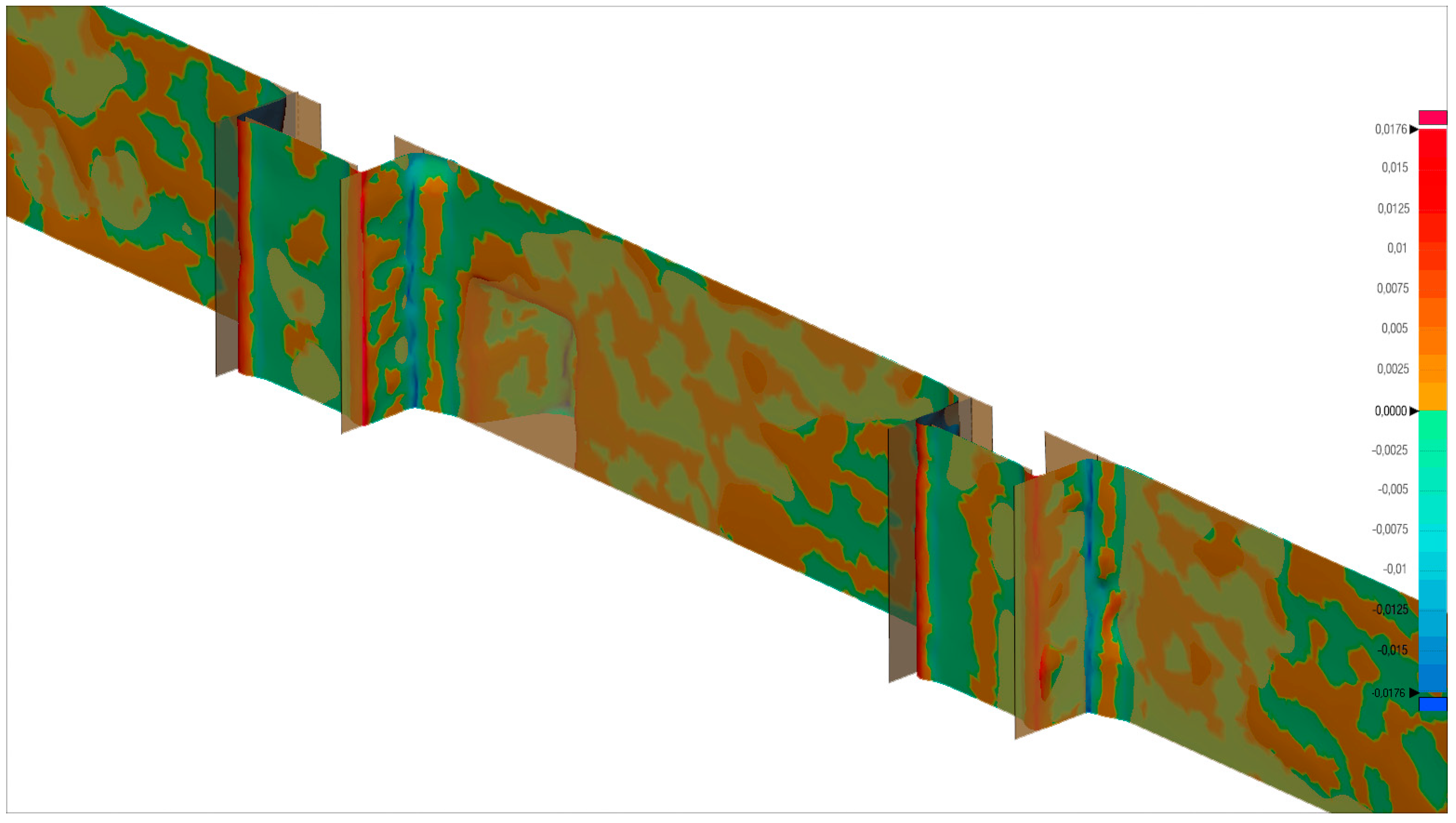
  • Segmentation of the meshed surface. Automatic process that, depending on variables related to accuracy parameters, consists of the subdivision of the mesh into regions of recognizable basic geometry (planes, spherical surfaces, conical surfaces, etc.) or generic (NURBs) (Figure 4).
  • Manual conversion of regions into CAD surfaces and their edition by means of manual modification tools to formalize the joints (Figure 5).
This last step is crucial when establishing the level of accuracy or fidelity of the final model with respect to the physical reality of the object treated. This aspect can be controlled by consulting the deviations produced between the mesh and the resulting CAD model (Figure 6).
The data collection used for photogrammetric capture was somewhat rugged because there was still activity in restoration works, so that there was areas of very poor quality in the final point cloud. This circumstance did not prevent executing the process described successfully for most of the object, extrapolating well-defined geometries to those areas (quite small compared to the total) lacking sufficient information. Since it was a pilot experience, the principal aim was to verify the proper functioning of the method proposed in general, ruther to obtain rigorous results for the whole three-dimensional model.
On the other hand, the reverse engineering software used is capable of generating complex NURB surfaces adapted to the mesh in regions bounded by the user, making it possible to include figurative elements in the surface model of the object (in this way the decorative medallions of the panels were developed). In any case, since the generation of these types of surfaces required more extensive processing times, it was necessary to make decisions regarding the formal complexity of the resulting object to optimize the times and resources. In that sense, it was decided to make geometric simplifications of certain elements, such as the capitals of the pilasters, the decorative elements of the frieze or the figurative elements of the window that illuminates the Sacristía de los Cálices.

3.1.2. Solid Modeling

This modeling phase includes the conversion, by means of CAD editing processes, of the surface composed in the previous phase into a set of three-dimensional graphic entities, of a solid nature, exportable to a BIM environment. It was developed through the following process scheme:
  • First, the CMD was transformed into a skin composed of multiple three-dimensional surfaces, of controlled generation, by means of reverse engineering software (as explained in the previous point).
  • Second, the skin was used as a mold to generate a solid-type entity inheriting the exact geometry and shape of the wall that limits the object of study. This process was performed in conventional CAD software, specifically Autodesk® AutoCAD® (Figure 7). The choice of this software had to do with two fundamental aspects: First, the graphic power that it makes available to the user; and second, the perfect connection at the export–import level with the BIM software that would be used for the creation and management of the information model. It is obvious that the selection process of the BIM software was carried out previously, and that the specific purpose of many of the processes followed and the decisions taken in this regard greatly influence the initial steps of the methodological proposal. However, it has been considered that the entire process would be understood more clearly following a consistent timeline. On the other hand, the obligatory time limit of this experience prevented the digital capture of the interior spaces that guaranteed the same level of accuracy on the inside of the wall as on the outside. The interior surfaces were drawn directly in CAD from the available graphic material (also in CAD format) of previous topographic and photogrammetric surveys. These were used to model, in the form of additional solids, a simplification of the interior spaces based on the theorization of their trace. These would be used to establish the necessary matter–space relationships in the BIM platform.
  • From the generated solid, a duplicate was carried out without figurative elements and formal configurations of certain complexity. It was necessary in order to guarantee the geometric base of different levels of detail within the BIM platform.
  • Finally, the detailed solid was cut using as a trail the ortho-images obtained from the photogrammetric capture (Figure 8). As previously discussed, the information model should be a very varied container of information, from brief geometric measurements to the detailed description of material and surface damages, through the location of stonework marks or the realization of complex chronological assignments. In that sense, two options were considered as the minimum unit of information of the model: the course or the ashlar. Both met a priori with the information requirements raised, but the course was discarded; it would need additional breaks when an element contained activities of different chronology and whose interfaces did not coincide with separation sores between stone courses.
The last process described involves implicit decisions of some importance in terms of knowledge of the object being considered and its impact on the information structure of the model. In this specific case, there were not enough records or documents to accurately deduce the thickness of the different layers that make up the structure of the façade and the existence of pieces arranged as keys that, through the supposed inner layer, join the outer layers of stone. The lack of certainty in this type of question, both geometric or formal and associated information, does not prevent the possibility of modeling entities based on well-founded hypotheses. It is possible to assign them relative values to various levels of knowledge (LOK) through created parameters specifically in the HBIM model, and to wait until accurate information is available that allows its update. LOK can be applied in two different ways in the information model: As a concept of standardization that specifies what minimum information a model or part of a model must contain to be considered as assigned to a LOK [5] (pp. 6–7), or as an intrinsic parameter to all the constituent elements of the model whose value defines a certain LOK of that element. In this case we refer to the second option.

3.2. HBIM Model Generation

As mentioned, the defining geometry of all the graphic entities that make up the model (model categories) are introduced into the BIM platform by importing from the three-dimensional model developed in CAD (as result of the process described in previous sections). The import process necessarily includes the categorization of each entity within one of the categories available on the platform. A relationship structure is formalized from the beginning. It properly encodes the structure of the defined conceptual model and satisfies the operational requirements of the model of information: Visualization, thematization, filtering, data management, dumping, etc. It is especially important to control the way in which the software establishes the relationships between the different elements (belonging or link), which should be present in the external databases linked to the model.
Focusing the problem on the object of study, it is decided to include the entities imported from the CAD within a family unit of wall category that, generated as model in-place component, will be the cohesive element of most of the functions related to the visualization and management of that part of the model. This wall instance is part of the project that will comprise, together with other partial models, the federated model of the temple. The composition of the specimen is based on the superposition of the different solids imported separately according to their level of detail, which allows, using a single object, the generation of visualizations at different representation scales. This also implies different possibilities in terms of the amount or depth of the information entered. In this way, each imported solid becomes a part associated with one of the following three levels of detail:
  • Low level of detail (Figure 9). It is made up of the complete solid of the wall fragment without figurative elements. It allows the generation of graphic documentation at the scale of representation that can be assimilated to a basic design for a new plant architecture (1/200 to 1/100). It faithfully reproduces the geometric and formal configuration of the element, the result of the exhaustive modeling process described above. A sectional view of this element is presented as a single solid entity, without discrimination of its material layers or real separate pieces.
  • Medium level of detail (Figure 10). Composed of the complete solid of the fragment including figurative elements. It responds to the same characteristics of the previous level, with more information at the graphic level. It allows the generation of graphic documentation on a scale of representation that can be assimilated to a basic project for a new plant architecture (1/100).
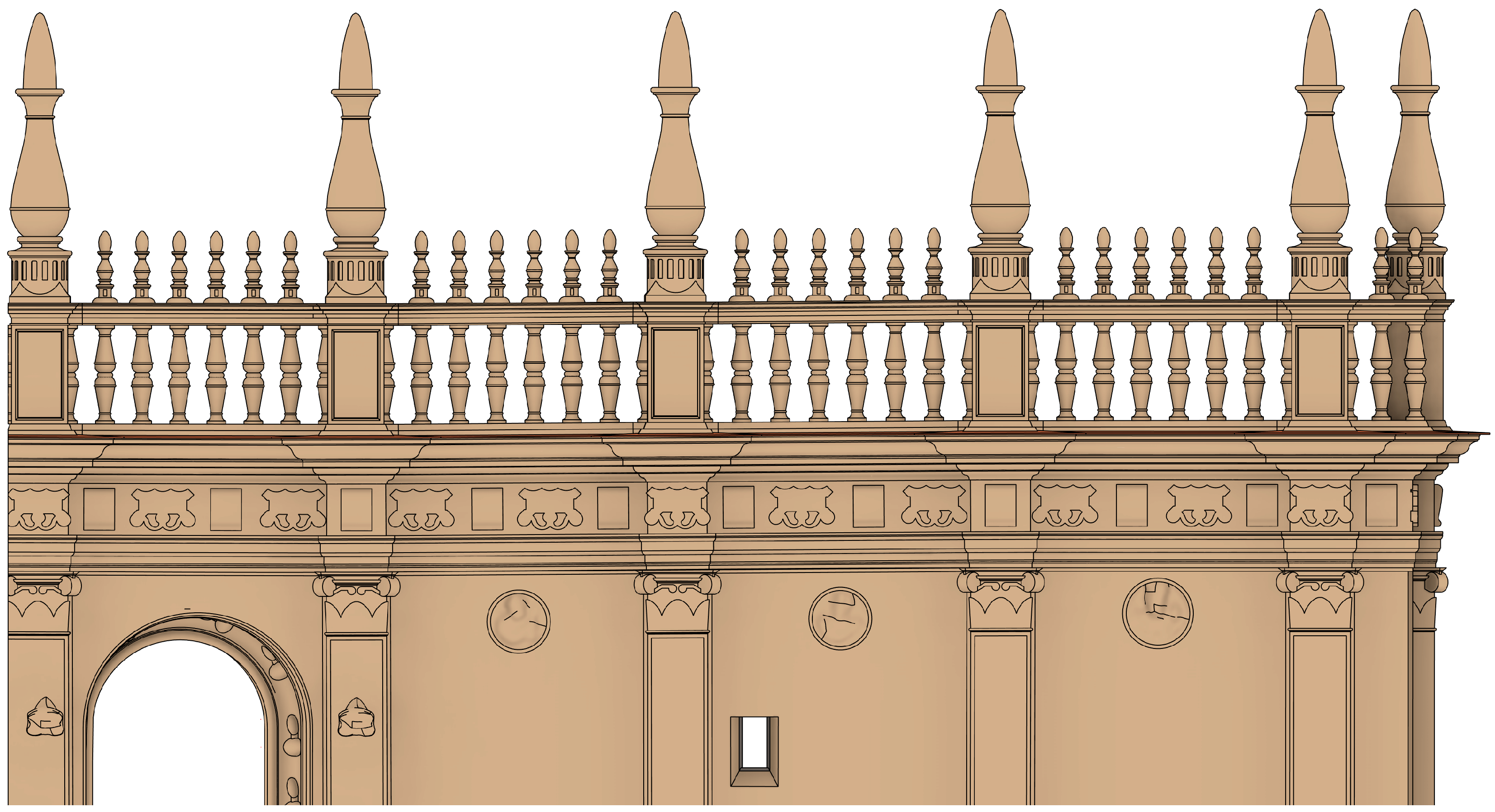
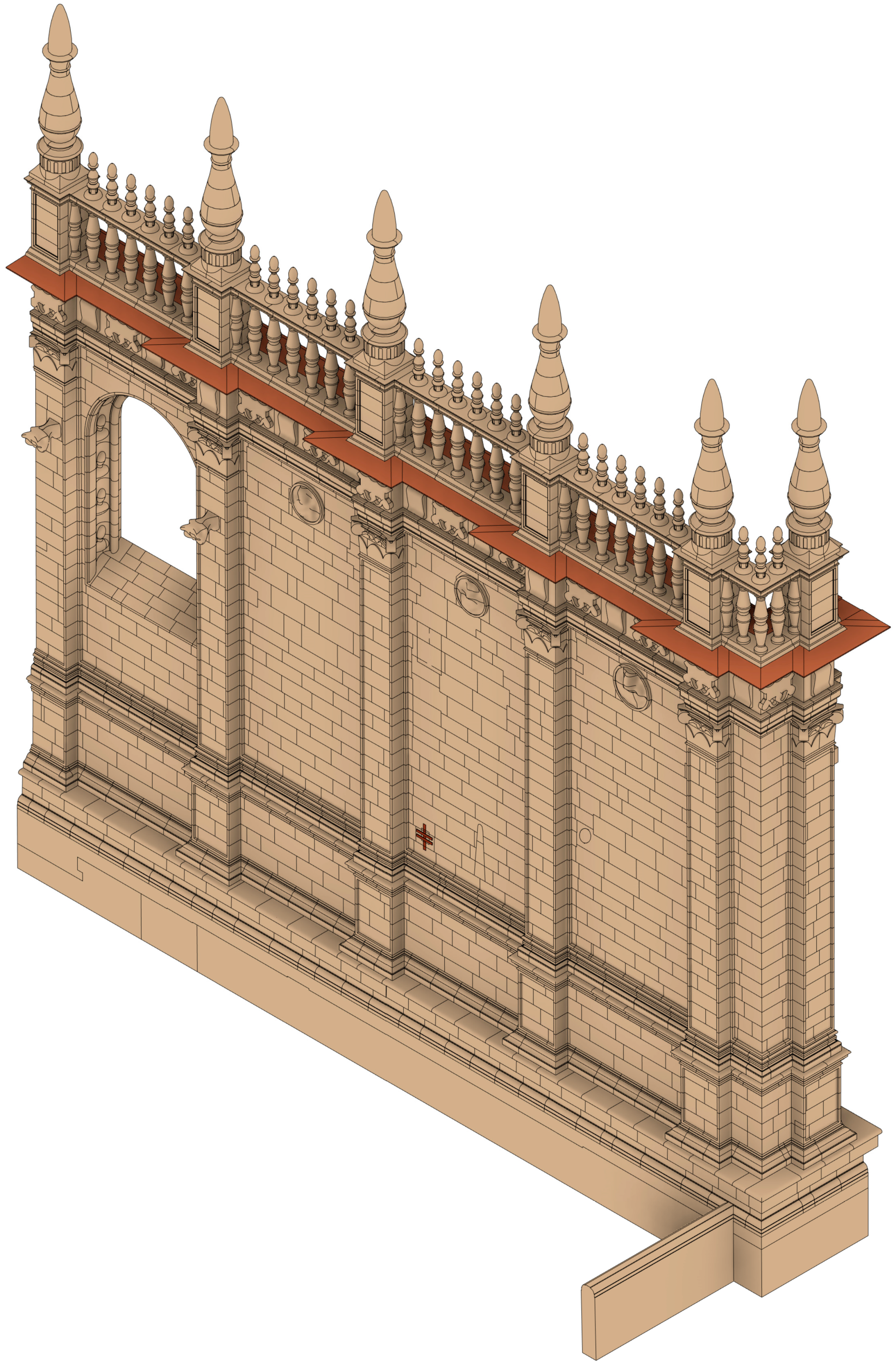
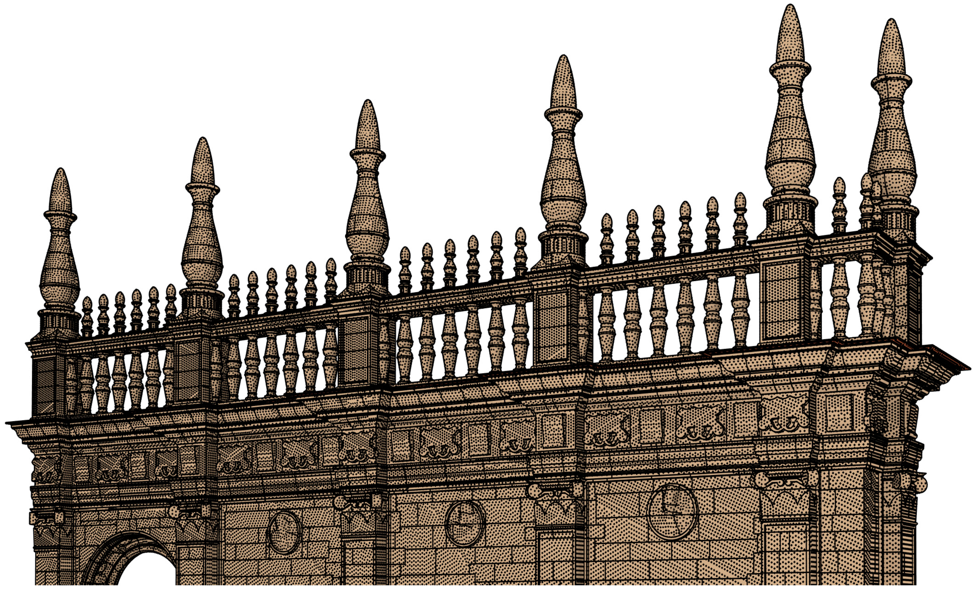
  • High level of detail (Figure 11). Composed of the set of solids resulting from the final cutting developed in the modeling process. It allows the generation of graphic documentation at the scale of representation comparable to a new plant architecture execution project (1/50 to 1/20), reaching from general projections of the object to construction details. In addition to faithfully reproducing the geometric and formal configuration of the element, it also includes the representation of the actual parts corresponding to the different strata that make up the wall.
These levels of detail are predefined in the BIM platform, so that it is possible to switch their display in any generated view of the model. The classification of imported solids at these levels is carried out by modifying their display properties within the family unit. Additionally, due to control needs of object selection, they are also classified by inclusion in custom subcategories (in this case within the wall category). The subcategory allows the subsequent selection of elements in a simple way for actions related to editing or information adding, overcoming the difficulties of having different graphic entities sharing the same location.
An additional level of control allows the switching of any view from showing original to showing parts, which gives rise to the possibility of independently selecting each three-dimensional solid included in the family unit (Figure 12). This capacity is derived from the options for grouping instances provided. They include the concept of assembly, whose function is to enable the grouping into a single entity of diverse elements with objectives related to information planning and advanced visualization of details of construction systems. The possibility of selecting pieces individually guarantees the introduction of detailed information to the minimum unit of discretization of the model, related to any field of knowledge or discipline. The information is entered by creating custom attributes (called parameters) that are associated with all entities belonging to one or more categories, allowing the subsequent edition of their values in a particular way, depending on the selection of objects done.
The information associated with the individual piece will necessarily be uniform in relation to the real object it represents (in this case, stone ashlar or building unit of ceramic or heterogeneous material), that is, the information related to its identification, linking or association, materiality, chronology, material or structural damages, etc. This condition prevents the association of information regarding aspects of a superficial nature such as surface damages (humidity, deposits, alterations, material losses, etc.) or characterizations related to the patina of any face. The inclusion of these aspects in the process is key to the achievement of the initially set objectives, among which is the use of the model in actions linked to the conservation and management of heritage.
In that sense, at the beginning of researching works, the possibility of modeling a very thin layer into the stratified structure of the conceptual model was considered. Its coding in the HBIM model would imply that each construction element would be linked to two thin external layers: One of finishing (with all the necessary subdivisions depending on its material and temporal nature) and another tessellated in pieces of 5×5 cm. that would house all the information related to the state of conservation of the constructive element. The material nature of the element would condition the existence or not of the finishing layer. Each tile of the second layer would have associated several parameters related to information of various kinds that would allow a subsequent visualization in conjunction with the element, as well as the quantification of its associated values. Materialization experiments of this method were carried out in partial models on various BIM platforms. In Autodesk® AutoCAD® Architecture®, the manual modeling of the tiles was proposed using large subdivided surfaces of AEC polygons type, capable of containing information and linking or containing other objects. This method proved not to be operative for objects of a certain formal complexity, since modeling was greatly complicated in its application to certain decorative or figurative elements. In an attempt to solve these limitations, we experimented with the generation of the tessellated thin layer automatically, by subdividing the outer surface of each architectural space (including the bounded outer space) with a meshing software and its subsequent extrusion to solid in CAD or directly in the BIM environment. This last method remained very limited in sectors of high formal complexity, where the miscellany of triangles of the meshed surface prevented its extrusion. Even so, it was introduced in some of the works developed, such as the one published in [3] (p. 416), applied to walls of a certain geometric simplicity.
The experience in the Renaissance quadrant has allowed the application of an evolution of these methods through the consideration of the thin layer as a set of elements simpler than the tiles. They are entities that, assimilated to points located in the center of the cells of a grid adapted to the model, could contain information and be linked to the parts or to the complete element that brings them together. There are scientific contributions that follow this line, but with limited operability in the field of heritage architecture, based directly on clouds of points separated from BIM information models, such as [59]. The formalization of these entities in BIM software has been carried out by modeling what have been called surface information points (SIP), consisting of family instances without specific categorization (generic models). Initially modeled as a simple point, its difficult visualization located on the surface of three-dimensional entities led us to replace them with a set of three vectors of variable length that are cut in the shape of a star (Figure 13a). The parameterization of vector lengths allowed the adequate visualization of the SIP at different scales (Figure 13b). Their status as a family instance guarantees the association of information parameters relative to the areas of knowledge already described.
The distribution of SIPs on the external surfaces of the wall was carried out by means of the execution of an algorithm programmed in Dynamo®. This is a graphical edition of algorithmic software linked to BIM software, already used in previous works such as [3,4]. This plugin allows the advanced treatment of the information contained in the model, both graphically and alphanumeric, through graphic programming routines based on the Python language. In this case, the algorithm developed consisted of two main actions:
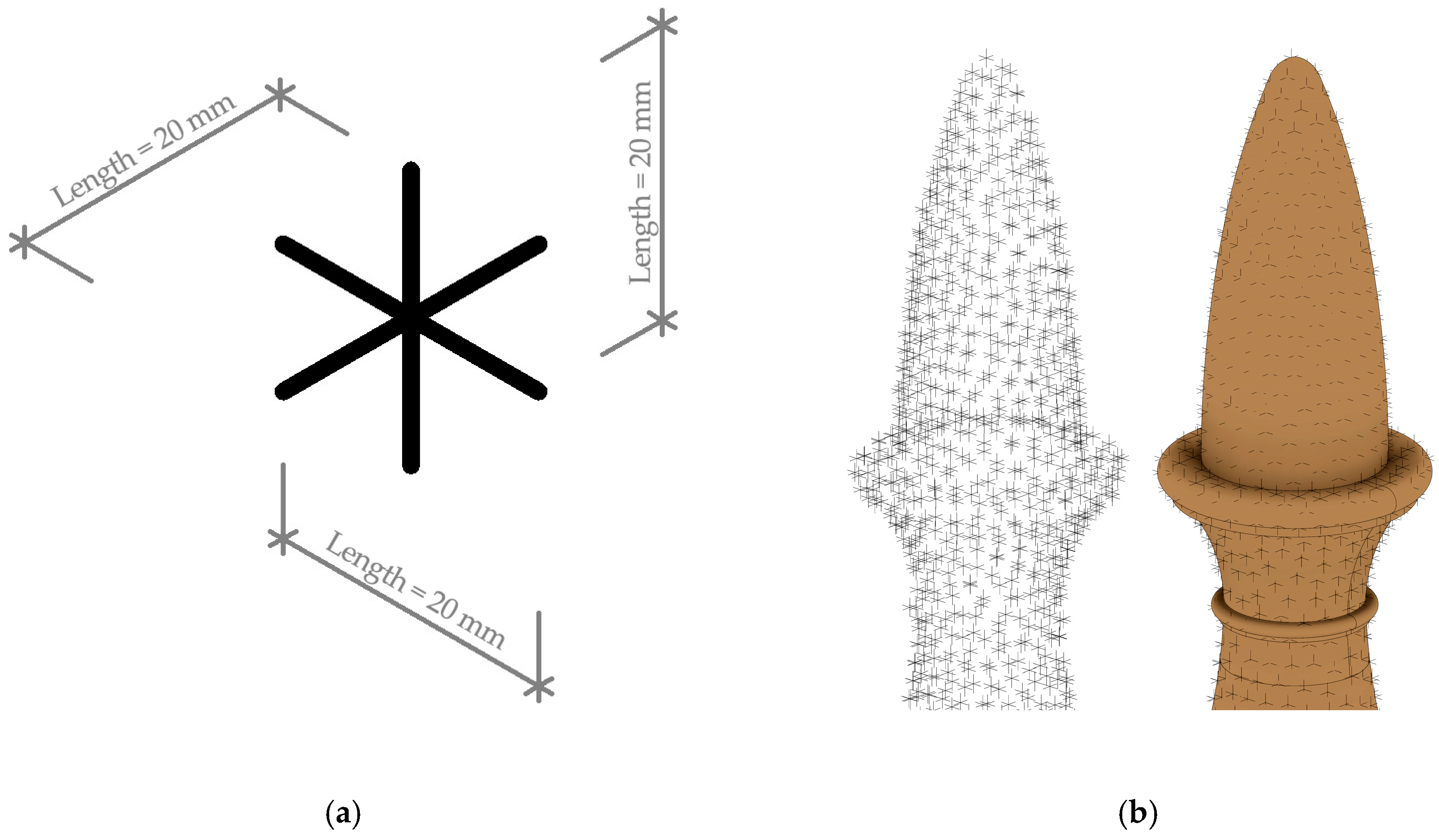
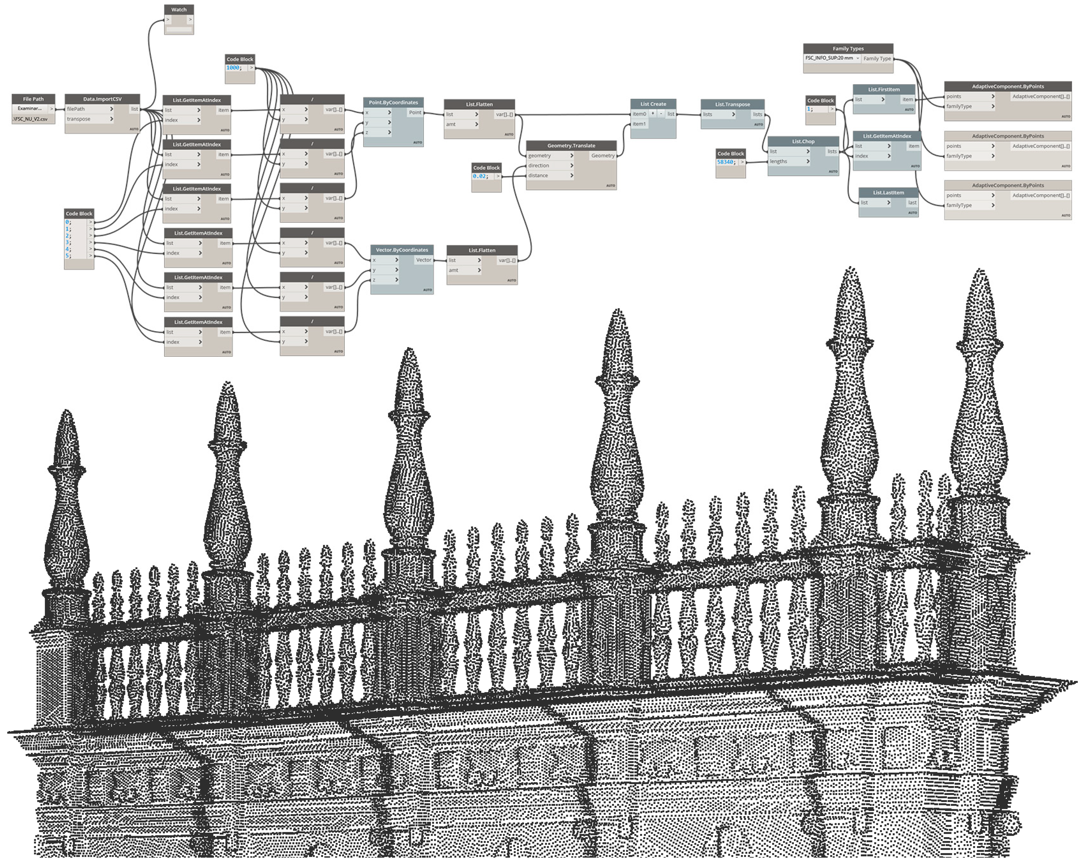
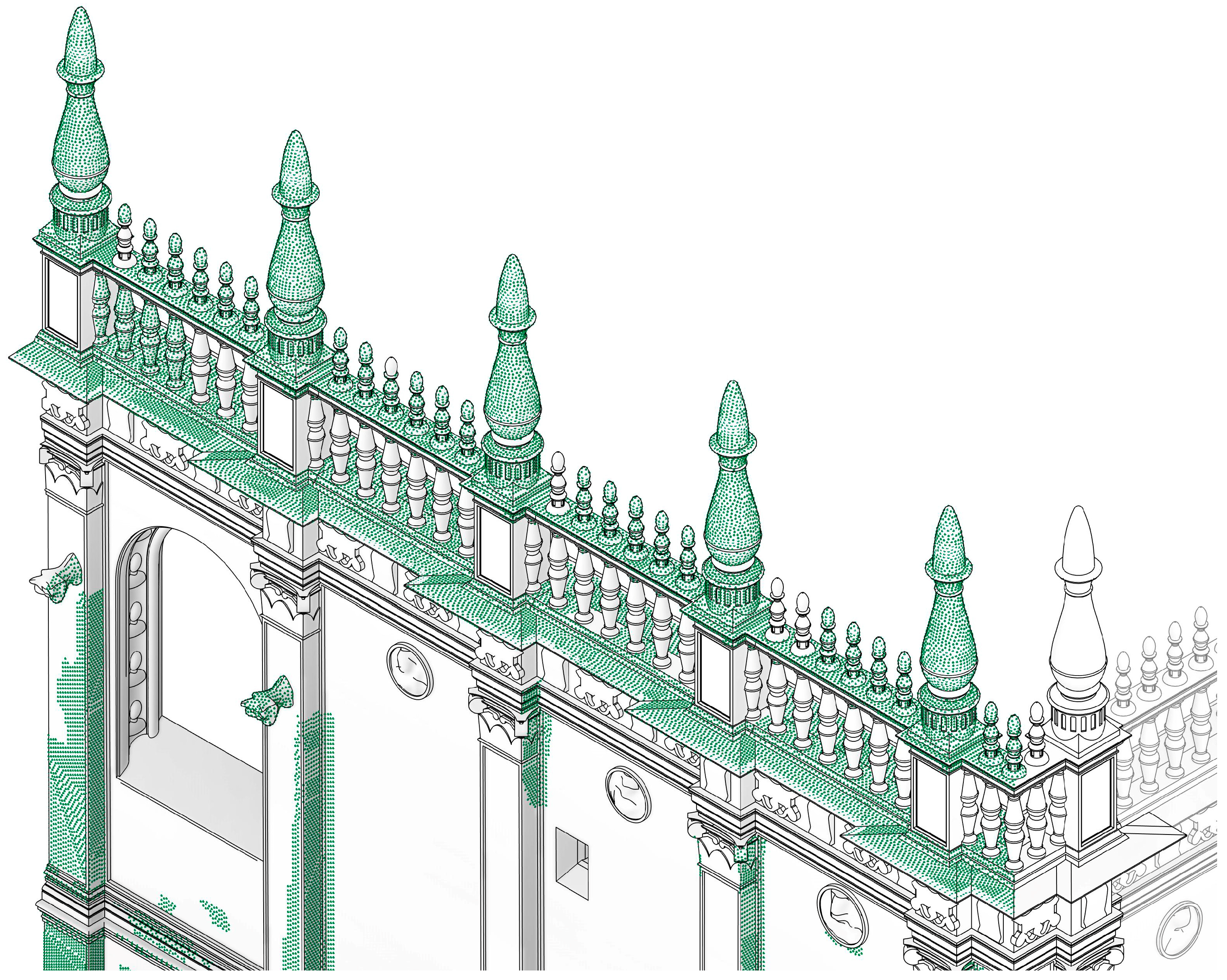
  • Automatic generation of a regular distributed cloud of points on the outer surfaces of the complete solid that forms the fragment of the treated wall (Figure 14). In this case, a regular 5×5 cm grid was chosen.
  • Automatic insertion of an instance of the SIP family in each of the constituent points of the previous cloud (Figure 15).
The treatment at a level of visualization and management of the inserted SIPs responds to the same operation as that used for any of the instances of the elements that make up the model, in such a way that the various values introduced in the associated parameters, as well as linking to other entities, allow, as will be seen later, the realization of alphanumeric queries or thematic visualizations through the adequate filtering of information.
The partial project of the sector studied is completed with the necessary entities to properly contextualize the façade fragment and allow an adequate testing of the methodology followed. For this, the following elements are conveniently imported and categorized:
  • Internal scope of the treated sector, corresponding to the Sacristía de los Cálices and the Patio de los Óleos, and its annexed dependencies. It was treated as a single element of a low detail (developable in the future) container of constructive and spatial elements of varied nature, so it has been introduced as a single family unit of the generic model category. In any case, the entities that comprise it have been classified through material and spatial subcategories that take up the stratified structure of the conceptual model, and allow the representation of spaces to be isolated, enabling architectural rigor of a certain complexity (Figure 16).
  • South façade section, treated as a wall category specimen at a low and medium level of detail.
  • Exterior pavement, treated as a soil category specimen at a low and medium level of detail.
  • Exempt columns located in the San Cristóbal Atrium, treated as pillar specimens at a low and medium level of detail.
On the other hand, it is noteworthy as an assessment of the partial objective achieved that an adequate structuring and ranking of the different entities allows the generation of high-accuracy graphic images based on rigorous coding (Figure 17). This result is obtained without the need to use advanced editing tools or the use of any type of additional software. In the following sections the treatment of these images will be addressed by filtering based on the information contained in the model.

3.3. Management Information: Treatment and Consultation

The management properties conferred automatically to each element, as well as the assignment of the parameters to the different entities that make up the model based on their category and the system of relationships implemented, represent the qualitative leap from a simple three-dimensional graphic model (developed in any digital drawing software or CAD) to a true information model (BIM or HBIM in this case) capable of offering all the advantages of a graphic database. Thus, once a value have been assigned to each parameter for each entity, based on the previously systematized information, it is possible to request information from the system. This information can consist of queries, information filtering or conditional searches, in the form of themed graphics (Figure 18 and Figure 19) or alphanumeric listings, which offer us new starting points when facing various types of analysis. It is also possible to request updated information, in real time, on certain aspects of the reality of the object being treated that allow decisions regarding its conservation or management (Figure 20 and Figure 21).
In that sense, the implementation of surface information management through SIPs allows graphic and quantitative control of relevant data in the field of preventive conservation, allowing consultations on the HBIM model in the form of tables of numerical data. Thus, in the specific case at hand, the inclusion of SIPs in a 5×5 cm controlled grid allows the generation of schedule tables with computation of areas related to certain existing damages or executed treatments. These tables can in turn be filtered according to parameters related to chronological phases (dates of specific interventions, drafting reports on damages status, etc.) or to specific areas of the model based on identification or membership attributes.
On the other hand, filtered info graphics or thematic graphic queries can be configured in combination with configuration tools of the views in which they are represented. In this way, the intentional visualization from certain points of view (if there are considered axonometric or conical perspectives) or using dihedral projections allow the contemplation of the relationships between elements and their associated information from new approaches difficult to reach without using this tool. The combination of several themed projections from the “phase ID” parameter of the Renaissance façade model allows certain deformations in the execution of some bodies to be directly related to specific construction phases recorded from the information collected and turned into the model itself (Figure 22).
Regarding the treatment, management and consultation of the model and its contained information, it is inevitable to talk about the qualification of the agents involved in these processes. The development of an HBIM model with a view to its effective exploitation in the field of conservation, intervention and management of heritage architecture entails (in addition to the work already described) its loading and implementation within the institution or entity responsible for such activities. The implementation of training courses in the use and application of that methodology and its tools is necessary in most cases.
Editing the information model in the BIM platform requires a high technical qualification, not only in relation to the tool management itself, but also to the knowledge in the field of architecture and related knowledge areas. However, the conception of this methodology is focused on the implementation of the HBIM model as administrator of all the information flows necessary for the correct execution of the actions related to knowledge, conservation, intervention and building management. These are currently governed by multidisciplinary groups of agents belonging to multiple branches of knowledge, and not always endowed with that technical qualification. It is therefore unavoidable to approach from this methodological proposal a procedural strategy that is able to withstand the performance of any type of agent with minimum qualification of transversal type. This can be achieved through the inclusion of generic tools for management, consultation and visualization of data in the aforementioned processes.
It is proposed to link the information in the graphic model to an external database that allows editing outside the BIM environment. This database is updated in real time from modifications in the model by automatically executing one or more scripts (programmed by graphic editions of algorithms). The same scripts would trigger the flow of information in the opposite direction, leading to the updating of the model based on the changes implemented in the database. This ensures, in turn, the dump of all graphic-based queries or themed images pre-configured in the BIM environment in the form of graphic documents (two- or three-dimensional) of universal format. Thus, technicians responsible for preventive conservation of the studied element do not require specific knowledge about BIM modeling software for the consultation or modification of information contained in the model. They simply need basic training to interact with tables and forms previously configured in the database, and to consult two-dimensional graphic documents dumped in PDF format or three-dimensional graphics dumped in Industry Foundation Classes (IFC) format. The latter graphics document format is operable at the visualization level in any free viewer available on the Network, enabling the consultation of the model through information filtering and visibility modifications of the different entities that compose it.
Therefore, the HBIM workflow is composed of the following elements:
  • Graphic model itself produced in the BIM editing platform.
  • Information associated with model parameters.
  • Linked databases for information management.
  • Associated documents collected in document registration processes or transferred from the model itself in successive updates. These documents are constituted as a documentary repository parallel to the HBIM model, which will be fed by the research and conservation actions that occur on the element studied.
As an illustrative example of this strategy, the approach developed for the treatment of the information hosted in the Renaissance façade model started from the initial assignment of a unique identifier to each constructive element of the model and the pieces that make it up. For constructive elements, this identifier consists of an alphanumeric code composed of the spatial coordinates derived from the position of each constructive element within the structure of alignments of structural planes identified in the conceptual model (Figure 23). The identifier is controlled using the custom shared “ID” parameter. Thus, the element of category wall that represents the enclosure of the Capilla de los Cálices is identified as “G-8-11”. For the pieces that comprise it, the identifier is the result of adding a four-digit number to the identifier of the construction element to which they belong. The generation of that number was done automatically by programming in Dynamo® a script that performs the complete task of composing the identifier and assigning it to each of the parts of the model (Figure 24).
Once all the entities have been identified and the classified information entered through parameters (according to previous sections), it is possible to generate planning tables that filter and classify the data according to any of the parameters involved or any of the relationship conditions between elements implemented in the model. The dump of these tables in Excel or Access format allows their subsequent treatment externally and the generation of a link with the model through the corresponding scripts mentioned above.
This workflow allows an unqualified agent for the BIM environment to operate in the database in order to update the information contained in the model (for example, the values of parameters related to preventive conservation actions, such as severity of damages or treatments applied). The automatic execution of the script coded for transferring information between database and graphic model guarantees not only the updating of that information in the model but also the updating of all graphic and alphanumeric dumps in the form of associated documents. That same agent can visualize and verify the result of the modifications made in the associated documents, which automatically become part of the documentary repository of the HBIM workflow. Additionally, it is possible to implement commands in the scripts that allow visual location (in real time) of the graphic entity linked to a particular database registration line (Figure 25).

4. Discussion

4.1. In Reference to the Survey or Digital Capture Phase

It is necessary to make some points about this phase of the work. The decision to opt for a technique of massive capture of data is widely justified at the beginning of Section 2.1. Among the available techniques (laser scanner and photogrammetry), photogrammetry is chosen due to economic and equipment accessibility issues. Many publications have already addressed the comparative study between both methods of capture, and it is not the objective of this research. The main interest is the general methodology of transformation of the data captured in an HBIM model with a very specific objective.
For the realization of the capture by digital photogrammetry, the usual methodology has been followed regarding the type of photographic shots, its processing in the appropriate software and the convenient topographic support by means of the correct orientation and scaling of the resulting point cloud. It was not an easy job, and the results were not highly accurate because, at the time of the data collection, work was being undertaken on the restoration of the façade. In any case, the results were satisfactory and sufficient for the objective sought.

4.2. In Reference to Three-Dimensional Modeling

In future development of the model described here, as well as in models developed in future projects, in addition to deepening the level of knowledge of the entities that already comprise it, it will be crucial to consider that the model should not only be the reflection of its current physical reality (material and documentary). It must also be a container of all those elements that are hidden or lost today (from archaeological excavations, documentary findings, etc.). These provide a diachronic reading of the building, influencing the possibility of performing analyzes from points of view impossible to achieve without the use of these models.
On the other hand, in reference to the modeling process, this work assumes from the beginning the objective of proposing and applying a method that guarantees the least possible deviation between the real object and the HBIM model. This objective implies supporting the process in reverse engineering tools that allow generating surfaces of any nature adapted to the irregular geometry that characterizes historical buildings such as the case study (irregularity due to defective execution processes, structural deformations, or other factors).
Thus, the proposal deviates from modeling methods classified in the research as semi-automatic parametric using NURBs, considered the most accurate in many of the publications of recent years. These methods involve theorization or rationalization of the profiles and trajectories extracted from the point cloud, omitting possible variations due to poor execution or decision changes occurred during the construction of the building, or even due to subsequent structural damages. These variations can be unavoidable clues for analyzes as important as the original trace of its elements, the transformation of the building along its history or its structural state. That is why this work proposes a semi-automatic non-parametric method: Generate the solid entities that make up the model from the filling of the space between the two “shells” (interior and exterior) that confine the material elements of the building. These shells are the result of precise conversion on NURBs surfaces (or on planes or quadrics in possible cases) of segmented regions of the cloud using reverse engineering tools.
The experience described in the research is a pioneer in the application of this method, and has allowed the verification of its applicability and possible ways of improvement. In this sense, it can be affirmed that the whole process depends on a capture of high quality data and precise segmentation of these in the line of work already referred to in Section 2.1 as [49,54].

4.3. In Reference to the Structure of the HBIM Model

As stated in the corresponding section, the structure of the model is subject to decisions on the nature of the entities that comprise it and on the definition of their relationships. These decisions would be endowed with great freedom if the process were to be carried out with a set of open source software applications (a perfectly valid option, and very interesting for future lines of progress). However, if commercial applications are chosen, it is necessary to carry out a prior adaptation process: The conceptual model initially proposed at the theoretical level must be translated into the systematization and hierarchy of entities and relationships established in the internal software code. This adaptation process will be different depending on the BIM platform chosen, but it is considered that it is achievable in any of the currently available platforms, regardless of the initial theoretical model. Thus, the effort to be used in adaptation will become one of the main variables that would be combined to make a suitable choice of software.
For the generation of the HBIM model described in this research, a specific commercial BIM software was used. It was not been possible to reproduce the methodology proposed in other commercial software due to time issues. That work is pending for future projects. The successful translation of the initial theoretical model into the object structure of BIM application is based on aspects related to categorization of objects and their visualization based on information filtering. These aspects are developed in all BIM software due to the very nature of this technology. Therefore, although there are variations in the implementation of such aspects in different software, it can be said that the proposed methodology is transferable to any commercial BIM application.
In another order of things, the authors of this work defend the statement that preventive conservation should include complete buildings and not just a part. The general methodological proposal of the authors on the application of BIM in heritage architecture includes not only preventive conservation but also the set of actions that encompasses the concept of guardianship. This refers, in general, to knowledge, management and conservation/intervention in these buildings, including scopes like structural analysis (in the line of works such as those published in [60,61]).
This work refers to a concrete experience of applying new methodological aspects in the modeling process and information management in an HBIM model, focused on the action of preventive conservation. This experience arises from a collaboration commitment between the research group of which the authors are part and the company dedicated to the preventive conservation of the façades of the Cathedral of Seville. The company provided information on the current state of the building and on the treatments applied, and the authors provided a method for the documentation and management of that information. Additionally, a simplified modeling of the interior spaces and the material elements that surround them was introduced with the objective of establishing metric and trace relations with the façade elements, thus supporting new analyses on the historical evolution of this part of the temple.

4.4. In Reference to the Treatment and Consultation of the Information

The implementation of the proposed workflow in a continuous process of preventive conservation, as is the case described, would be a very important advance in the treatment of information. In any case, it is proposed that the adoption of this system begin in a first process of objectification of concepts in three main and related groups:
  • A group containing information linked to knowledge that, as a basis for the process of valuing the managed assets, includes the information collected that is part of the aforementioned document repository.
  • The HBIM information model itself, linked to the concepts of the previous group and container of all the data associated with each of the elements that make it up, depending on the information structure already raised, and with the required depth (LOK) for the objectives sought.
  • The group formed by the different operations that are selected as feasible and convenient based on analysis derived from the first two groups. These operations would consist of previous, parallel and subsequent works to the very fact of conservation. Its results, once executed, would nourish relevant information to the first group. In this way, the cycle would be closed in a loop of continuous updating capable of feeding and sustaining the different processes linked to the conservation of the monument.

5. Conclusions

This work has led to the development and improvement of a methodology capable of supporting the implementation of HBIM heritage information modeling with guarantees, in the processes of knowledge, intervention and management of architectural heritage in general, and preventive conservation actions in particular. Thus, the contributions to the knowledge and analysis of the model studied are the result of said methodological innovation. However, as stated before, the main contribution is not in the heritage use of the BIM, already explored in the many experiences referred to in the text, but in the approach to it from an integral perspective of the protection of the patrimonial fact. The issue of the use of BIM in architectural heritage has been placed not only in the partial scope of the accurate graphic survey but also in its role as a wealth management tool accessible from the various disciplines involved.
The model was developed with support in digital metric captures analyzed and interpreted with the methodological keys of architectural survey. The model arises, consequently, from a proposal of interpretation of the metric data based on archaeological and architectural knowledge of the element studied. The translation of the raw data of the capture into three-dimensional graphic entities, that contain and generate information, was based on a conceptual theoretical model. This evolved from previous work reaching the high levels of complexity required by the studied reality.
For greater viewing and management flexibility, three levels of development were processed in parallel: Two that, differentiated into two levels of detail at the formal level, cover the entire element studied as a single entity, and another, derived from the exploded view of the previous one, where each building unit of the set was delimited. The single entity models incorporate the information parameters related to the whole element (whether this is the complete building unit or a fragment of it). This information is completed with the values of each piece of the exploded model, where the parameters associated with the various actions that the model has to support are incorporated. Among these, this research highlighted those of preventive conservation as culmination through the experience. In the latter case, the implementation of so-called surface information points (SIPs) stands out as methodological innovation. These entities, of great versatility, allowed the incorporation of information on the surface of models of great formal complexity.
Systematized and standardized information entry and exit protocols were developed through external databases linked to the graphic model, as well as data import–export flows. These allow the visualization of the model through free visors of great usability, allowing interaction with the model of agents involved without specialized training in BIM methodology. This interaction was tested as positive for the analysis processes based on graphic queries obtained from the filtering of alphanumeric information contained by the model and linked to the various databases. This link is considered key in the conception of the HBIM model as an essential tool in the maintenance and management of updated information on the object of study. In any case, unlike other academic contributions, this work does not consider the model as a mere container or receiver of information, but as an active tool that supports reflection and decision making at an analytical level. The model itself is capable of generating information that channels new knowledge about the complex transformation processes that characterize historical architecture.

Author Contributions

All authors have read and agree to the published version of the manuscript. Conceptualization, R.A.-F. and M.C.-R.; Methodology, R.A.-F. and M.C.-R.; Software, R.A.-F.; Validation, M.C.-R.; Visualization, R.A.-F.; Writing—original draft, R.A.-F.; Writing—review & editing, R.A.-F. and M.C.-R.

Funding

The exposed experience constitutes one of the actions developed in the HAR2016-78113-R Project, supported by the Ministry of Science, Innovation and Universities of the Government of Spain, R & D & I Plan, with acronym TUSOSMOD.

Acknowledgments

The authors express their gratitude to their colleagues in the research group HUM799 “Heritage knowledge strategies” and to the company Artyco. S.L.

Conflicts of Interest

The authors declare no conflict of interest.

References

  1. Angulo Fornos, R. Construcción de la base gráfica para un sistema de información y gestión del patrimonio arquitectónico: Casa de Hylas. Arqueol. la Arquit. 2012, 11–25. [Google Scholar] [CrossRef] [Green Version]
  2. Castellano Román, M. Generación de un modelo de información del patrimonio inmueble en el momento de su protección jurídica. Rev. EGA 2015, 26, 266–277. [Google Scholar] [CrossRef] [Green Version]
  3. Angulo Fornos, R. Digital models applied to the analysis, intervention and management of architectural heritage. In Proceedings of the Building Information Modeling (BIM) in Design, Construction and Operations; WIT Press: Bristol, UK, 2015; Volume 149, pp. 407–418. [Google Scholar]
  4. Angulo Fornos, R.; Pinto Puerto, F.; Rodríguez Medina, J.; Palomino, A. Digital Anastylosis of the Remains of a Portal by Master Builder Hernán Ruiz: Knowledge Strategies, Methods and Modeling Results. Digit. Appl. Archaeol. Cult. Herit. 2017, 7, 32–41. [Google Scholar]
  5. Castellano Román, M.; Pinto Puerto, F. Dimensions and Levels of Knowledge in Heritage Building Information Modeling, HBIM: The model of the Charterhouse of Jerez (Cádiz, Spain). Digit. Appl. Archaeol. Cult. Herit. 2019, 14, e00110. [Google Scholar]
  6. Castellano Román, M.; Pinto Puerto, F. HBIM oriented towards the master plan of the charterhouse of Jerez (Cádiz, Spain). Int. Arch. Photogramm. Remote Sens. Spat. Inf. Sci. 2019, XLII, 285–290. [Google Scholar] [CrossRef] [Green Version]
  7. Pocobelli, D.P.; Boehm, J.; Bryan, P.; Still, J.; Grau-Bové, J. Building information models for monitoring and simulation data in heritage buildings. Int. Arch. Photogramm. Remote Sens. Spat. Inf. Sci. 2018, XLII, 909–916. [Google Scholar] [CrossRef] [Green Version]
  8. Fonnet, A.; Alves, N.; Sousa, N.; Guevara, M.; Magalhaes, L. Heritage BIM integration with mixed reality for building preventive maintenance. In Proceedings of the 2017 24o Encontro Português de Computação Gráfica e Interação (EPCGI); Institute of Electrical and Electronics Engineers (IEEE): Guimarães, Portugal, 2017; pp. 1–7. [Google Scholar]
  9. Lo Turco, M.; Mattone, M.; Rinaudo, F. Metric survey and BIM technologies to record decay conditions. Int. Arch. Photogramm. Remote Sens. Spat. Inf. Sci. 2017, XLII-5/W1, 261–268. [Google Scholar] [CrossRef] [Green Version]
  10. Brumana, R.; Dellatorre, S.; Oreni, D.; Previtali, M.; Cantini, L.; Barazzetti, L.; Franchi, A.; Banfi, F.; Della Torre, S.; Oreni, D.; et al. HBIM challenge among the paradigm of complexity, tools and preservation: The basilica Di collemaggio 8 years after the earthquake (L’aquila). Int. Arch. Photogramm. Remote Sens. Spat. Inf. Sci. - ISPRS Arch. 2017, XLII, 97–104. [Google Scholar] [CrossRef] [Green Version]
  11. Lo Turco, M.; Caputo, F.; Fusaro, G. From integrated survey to the parametric modeling of degradations. A feasible workflow. In Proceedings of the 6th International Confrence EuroMED 2016; Ioannides, M., Moropoulou, A., Fresa, A., Rajcic, V., Eds.; Springer International Publishing: Nicosia, Cyprus, 2016; pp. 579–589. [Google Scholar]
  12. Carrero Santamaría, E. La sacristía catedralícia en los reinos hispanos. Evolución topográfica y tipo arquitectónico. Liño Rev. Anu. Hist. del arte 2005, 49–75. [Google Scholar]
  13. Recio Mir, Á. “Sacrum Senatum”: Las Estancias Capitulares de la Catedral de Sevilla; Fundación Focus-Abengoa y Universidad de Sevilla: Sevilla, Spain, 1999; ISBN 84-472-0469-3. [Google Scholar]
  14. Arévalo Rodríguez, F. El amurallamiento externo de la mezquita aljama de la Sevilla almohade. In Actas de XVIII Edición Aula Hernán Ruiz: La catedral sin la catedral; Cabildo Catedral de Sevilla: Sevilla, Spain, 2011; pp. 7–56. ISBN 978-84-938923-0. [Google Scholar]
  15. Tabales Rodríguez, M.Á.; Jiménez Sancho, Á. La Cilla de la Catedral y el sector meridional de la mezquita aljama de Sevilla. In Magna Hispalensis (I) Recuperación de la aljama almohade; Aula Hernán Ruiz, Cabildo Metropolitano: Granada, Spain, 2002; pp. 229–296. ISBN 84-7170-183-9. [Google Scholar]
  16. Morales Martínez, A.J. La arquitectura de la catedral de Sevilla en los siglos XVI, XVII y XVIII. In La catedral de Sevilla; Guadalquivir: Sevilla, Spain, 1984; pp. 173–215. [Google Scholar]
  17. Morales Martínez, A.J. La Sacristía Mayor de la Catedral de Sevilla; Diputación Provincial de Sevilla: Sevilla, Spain, 1984; ISBN 84-505-0097-4. [Google Scholar]
  18. Rodríguez Estévez, J.C. Los canteros de la catedral de Sevilla. Del Gótico al Renacimiento; Diputación Provincial de Sevilla: Sevilla, Spain, 1998; ISBN 84-7798-143-4. [Google Scholar]
  19. Rodríguez Estévez, J.C. Martín de Gainza (ca.1505-1556). In Artistas Andaluces y artífices del arte andaluz; Publicaciones Comunitarias. Grupo Hércules: Sevilla, Spain, 2011; pp. 255–288. ISBN 9788493673673. [Google Scholar]
  20. Gentil Baldrich, J.M. La traza oval y la sala capitular de la Catedral de Sevilla: Una aproximación geométrica. In Qvatro. Edificios sevillanos; Fidas-Demarcación COA Sevilla: Sevilla, Spain, 2008; pp. 75–147. [Google Scholar]
  21. Gómez Martínez, J. El gótico español de la Edad Moderna: bóvedas de crucería; Arte y Arqueología / Universidad de Valladolid 14; Secretariado de Publicaciones e Intercambio Científico, Universidad de Valladolid: Valladolid, 1998; ISBN 84-7762-845-9. [Google Scholar]
  22. Sierra Delgado, R. Diego de Siloé y la nueva fábrica de la Sacristía Mayor de la Catedral de Sevilla; Colección Arquitectura No 31; Universidad de Sevilla, Secretariado de Publicaciones: Sevilla, Spain, 2012; ISBN 978-84-472-1416-7. [Google Scholar]
  23. Pinto Puerto, F. La Sacristía de los Cálices: Aportaciones desde el análisis de sus fábricas y los sistemas de control formal; Cabildo Catedral de Sevilla: Sevilla, Spain, 2013. [Google Scholar]
  24. Jiménez Martín, A. Anatomía de la Catedral de Sevilla, 1st ed.; Diputación de Sevilla. Servicio de Archivo y Publicaciones: Sevilla, Spain, 2013; ISBN 978-8477983446. [Google Scholar]
  25. Morales Martínez, A.J. Sacristías del renacimiento en Andalucía. In Arquitectura religiosa del siglo XVI en España y Ultramar; del Lacarra Ducay, M.C., Ed.; Institución Fernando el Católico (Excma. Diputación de Zaragoza): Zaragoza, Spain, 2004. [Google Scholar]
  26. Pinto Puerto, F. Las esferas de piedra: Sevilla como lugar de encuentro entre arte y ciencia del Renacimiento; Arte / Diputación de Sevilla. Serie 1a; 36; Diputación de Sevilla, Área de Cultura y Deportes, Servicio de Archivo y Publicaciones: Sevilla, Spain, 2002; ISBN 84-7798-182-5. [Google Scholar]
  27. Palacios Gonzalo, J.C. La cantería medieval: La construcción de la bóveda gótica española; ML; 8; Munilla-Lería: Madrid, Spain, 2009; ISBN 9788489150843. [Google Scholar]
  28. Hichri, N.; Stefani, C.; De Luca, L.; Veron, P.; Hamon, G. From Point Cloud To Bim: A Survey of Existing Approaches. ISPRS - Int. Arch. Photogramm. Remote Sens. Spat. Inf. Sci. 2013, XL-5/W2, 343–348. [Google Scholar] [CrossRef] [Green Version]
  29. Brumana, R.; Oreni, D.; Barazzetti, L.; Cuca, B.; Previtali, M.; Banfi, F. Survey and Scan to BIM Model for the Knowledge of Built Heritage and the Management of Conservation Activities. In Digital Transformation of the Design, Construction and Management Processes of the Built Environment; Springer: Cham, Switzerland, 2020; pp. 391–400. [Google Scholar]
  30. Nieto Julián, J.E. Generación de modelos de información para la gestión de una intervención: La cárcel de la Real Fábrica de Tabacos de Sevilla. Virtual Archaeol. Rev. 2012, 3, 63–67. [Google Scholar] [CrossRef] [Green Version]
  31. Buill Pozuelo, F.; Núñez Andrés, A.; Puche Fontanilles, J.M.; Macias, J.M. Geometric analysis of the original stands of roman amphitheater in Tarragona: Method and results. J. Cult. Herit. 2015, 16, 640–647. [Google Scholar] [CrossRef] [Green Version]
  32. Rodríguez-Moreno, C.; Reinoso-Gordo, J.F.; Rivas-Lpez, E.; Gmez-Blanco, A.; Ariza-Lpez, F.J.; Ariza-Lpez, I. From point cloud to BIM: An integrated workflow for documentation, research and modeling of architectural heritage. Surv. Rev. 2018, 50, 1–20. [Google Scholar] [CrossRef]
  33. Fai, S.; Graham, K.; Duckworth, T.; Wood, N.; Attar, R. Building Information Modeling and Heritage Documentation. 23rd Int. Symp. Int. Sci. Comm. Doc. Cult. Herit. 2011, 12–13. [Google Scholar]
  34. Dore, C.; Murphy, M. Integration of Historic Building Information Modeling ( HBIM ) and 3D GIS for Recording and Managing Cultural Heritage Sites. Proc. 2012 18th Int. Conf. Virtual Syst. Multimedia, VSMM 2012 Virtual Syst. Inf. Soc. 2012, 369–376. [Google Scholar]
  35. Bregianni, A. BIM Development for Cultural Heritage Management, National Technical University of Athens—Polytechnic University of Milan. 2013. Available online: http://dspace.lib.ntua.gr/bitstream/123456789/8297/1/bregianni_thesis_rv.pdf (accessed on 6 February 2015).
  36. Rua, H.; Gil, A. Automation in heritage—Parametric and associative design strategies to model inaccessible monuments: The case-study of eighteenth-century Lisbon Águas Livres Aqueduct. Digit. Appl. Archaeol. Cult. Herit. 2014, 1, 82–91. [Google Scholar] [CrossRef]
  37. Quattrini, R.; Malinverni, E.; Clini, P.; Nespeca, R.; Orlietti, E. From TLS to HBIM. High quality semantically-aware 3D modeling of complex architecture. In Proceedings of the The International Archives of the Photogrammetry, Remote Sensing and Spatial Information Sciences, Ávila, España, 25–27 February 2015; Volume XL-5/W4, pp. 367–374. [Google Scholar]
  38. Lo Turco, M.; Bruno, E. Historic Building Information Modeling: From historical database platform to fully suitable and multidisciplinary design instruments. In Proceedings of the World Heritage and Degradation. Smart Design, Planning and Technologies, Naples-Capri, Italy, 16–18 June 2016. [Google Scholar]
  39. Baik, A. From point cloud to Jeddah Heritage BIM Nasif Historical House—Case study. Digit. Appl. Archaeol. Cult. Herit. 2017, 4, 1–18. [Google Scholar] [CrossRef]
  40. Cogima, C.; Paiva, P.; Dezen Kempter, E.; Garcia de Carvalho, M.A.; Soibelman, L. The Role of Knowledge-Based Information on BIM for Built Heritage. Advances in Informatics and Computing in Civil and Construction Engineering; Mutis, I., Timo, H., Eds.; Springer: Chicago, IL, USA, 2019. [Google Scholar]
  41. Garagnani, S. Building Information Modeling and real world knowledge: A methodological approach to accurate semantic documentation for the built environment. 2013 Digit. Herit. Int. Congr. 2013, 489–496. [Google Scholar]
  42. Oreni, D.; Brumana, R.; Banfi, F.; Bertola, L.; Barazzetti, L.; Cuca, B.; Previtali, M.; Roncoroni, F. Beyond crude 3D models: From point clouds to historical building information modeling via NURBS. Lect. Notes Comput. Sci. (including Subser. Lect. Notes Artif. Intell. Lect. Notes Bioinformatics) 2014, 8740, 418–426. [Google Scholar]
  43. Barazzetti, L.; Banfi, F.; Brumana, R.; Previtali, M. Creation of Parametric BIM Objects from Point Clouds Using Nurbs. Photogramm. Rec. 2015, 30, 339–362. [Google Scholar] [CrossRef]
  44. Tommasi, C.; Achille, C.; Fassi, F. From point cloud to BIM: A modeling challenge in the cultural heritage field. Int. Arch. Photogramm. Remote Sens. Spat. Inf. Sci. - ISPRS Arch. 2016, 41, 429–436. [Google Scholar] [CrossRef]
  45. Angjeliu, G.; Cardani, G.; Coronelli, D. A parametric model for ribbed masonry vaults. Autom. Constr. 2019, 105. [Google Scholar] [CrossRef]
  46. Oreni, D.; Brumana, R.; Georgopoulos, A.; Cuca, B. HBIM for Conservation and Management of Built Heritage: Towards a Library of Vaults and Wooden Bean Floors. In Proceedings of the ISPRS Annals of the Photogrammetry, Remote Sensing and Spatial Information Sciences, Strasbourg, France, 2–6 September 2013; Volume II-5/W1, pp. 215–221. [Google Scholar]
  47. Thomson, C.; Boehm, J. Automatic geometry generation from point clouds for BIM. Remote Sens. 2015, 7, 11753–11775. [Google Scholar] [CrossRef] [Green Version]
  48. Macher, H.; Landes, T.; Grussenmeyer, P. From Point Clouds to Building Information Models: 3D Semi-Automatic Reconstruction of Indoors of Existing Buildings. Appl. Sci. 2017, 7, 1030. [Google Scholar] [CrossRef] [Green Version]
  49. Bassier, M.; Klein, R.; Van Genechten, B.; Vergauwen, M. IFCwall reconstruction from unstructured point clouds. ISPRS Ann. Photogramm. Remote Sens. Spat. Inf. Sci. 2018, 4, 33–39. [Google Scholar] [CrossRef] [Green Version]
  50. Demarsin, K.; Vanderstraeten, D.; Volodine, T.; Roose, D. Detection of closed sharp edges in point clouds using normal estimation and graph theory. CAD Comput. Aided Des. 2007, 39, 276–283. [Google Scholar] [CrossRef]
  51. Weber, C.; Hahmann, S.; Hagen, H. Methods for Feature Detection in Point Clouds. Vis. Large Unstructured Data Sets IRTG Work. 2010, 19, 90–99. [Google Scholar]
  52. Xiong, X.; Huber, D. Using Context to Create Semantic 3D Models of Indoor Environments. In Proceedings of the British Machine Vision Conference, Aberystwyth, UK, 31 August–3 September 2010; Labrosse, F., Zwiggelaar, R., Liu, Y., Tiddeman, B., Eds.; BMVA Press: Durham, UK, 2010. [Google Scholar]
  53. Núñez Andrés, A.; Buill Pozuelo, F.; Regot, J.; de Mesa, A. Use of robust methods to determine quadratic surfaces: Application to heritage. J. Archaeol. Sci. 2013, 40, 1289–1294. [Google Scholar] [CrossRef]
  54. Riveiro, B.; DeJong, M.J.; Conde, B. Automated processing of large point clouds for structural health monitoring of masonry arch bridges. Autom. Constr. 2016, 72, 258–268. [Google Scholar] [CrossRef]
  55. Palestini, C.; Basso, A.; Graziani, L. Integrated photogrammetric survey and bim modeling for the protection of school heritage, applications on a case study. In Proceedings of the International Archives of the Photogrammetry, Remote Sensing and Spatial Information Sciences—ISPRS Archives, Riva del Garda, Italy, 4–7 June 2018; pp. 821–828. [Google Scholar]
  56. Antón, D.; Medjdoub, B.; Shrahily, R.; Moyano Campos, J.J. Accuracy evaluation of the semi-automatic 3D modeling for historical building information models. Int. J. Archit. Herit. 2018, 12, 790–805. [Google Scholar] [CrossRef] [Green Version]
  57. Nieto Julián, J.E.; Moyano, J.J.; García Gascón, Á.; García, Á. Estudio constructivo del palacio de los niños de Don Gome (Andújar, Jaén), gestionado desde el proyecto HBIM. Virtual Archaeol. Rev. 2019, 10, 84–97. [Google Scholar]
  58. González Pérez, C. Information Modeling for Archaeology and Anthropology: Software Engineering Principles for Cultural Heritage, 1st ed.; Springer: Berlin/Heidelberg, Germany, 2018. [Google Scholar]
  59. Soler, F.; Melero, F.J.; Luzón, M.V. A complete 3D information system for cultural heritage documentation. J. Cult. Herit. 2017, 23, 49–57. [Google Scholar] [CrossRef]
  60. Bassier, M.; Hadjidemetriou, G.; Vergauwen, M.; Van Roy, N.; Verstrynge, E. Implementation of scan-to-BIM and FEM for the documentation and analysis of heritage timber roof structures. Digit. Heritage. Prog. Cult. Herit. Doc. Preserv. Prot. 2016, 10058 LNCS, 79–90. [Google Scholar]
  61. Angjeliu, G.; Cardani, G.; Coronelli, D. Digital modeling and analysis of masonry vaults. ISPRS Ann. Photogramm. Remote Sens. Spat. Inf. Sci. 2019, 42, 83–89. [Google Scholar] [CrossRef] [Green Version]
Figure 1. Location and recent photograph of the object of study.
Applsci 10 02428 g001
Figure 2. Generic scheme of the matrix system of relationships of the HBIM model, focused on the material stratum of the conceptual model. (a) Federated model. Building. (b) Partial model. Building Sector. (c) Family instance. Sustaining Element. (d) Piece. Constructive element.
Applsci 10 02428 g002
Figure 3. Partial view of the mesh surface obtained from photogrammetric point cloud. Mesh size: 1,771,241 triangles.
Applsci 10 02428 g003
Figure 4. Partial view of mesh segmentation in regions of recognizable geometries. The low quality of the mesh in areas of high formal complexity (such as decorative elements) due to the difficulties mentioned in the survey process, have produced an excess of regions. This circumstance has not prevented the implementation of the proposed modeling method for the surfaces that define the general shape of the façade.
Applsci 10 02428 g004
Figure 5. Exterior and interior views of the CAD model once edited.
Applsci 10 02428 g005
Figure 6. Partial view of the verification of deviations between the meshed surface and the CAD model. The maximum geometric deviations with respect to the surfaces that define the general shape of the façade do not exceed 0.005 m. As stated in the text, the decorative elements have been simplified and have not been taken into account in the estimation of deviations.
Applsci 10 02428 g006
Figure 7. CAD editing process. Simplified solid, reference ortho-image, exploded drawing in two dimensions and its application to the final exploded in three-dimensional solid entities.
Applsci 10 02428 g007
Figure 8. Graphic model of complete CAD solids.
Applsci 10 02428 g008
Figure 9. Instance of wall displayed at low level of detail.
Applsci 10 02428 g009
Figure 10. Instance of wall displayed at medium level of detail.
Applsci 10 02428 g010
Figure 11. Instance of wall displayed in high detail.
Applsci 10 02428 g011
Figure 12. Instance of wall visualized at high level of detail with individual piece selection and detail.
Applsci 10 02428 g012
Figure 13. (a) Surface Information Points (SIP). Graphic description of parameterized family. (b) SIP distribution detail on the surface of the model entities.
Applsci 10 02428 g013
Figure 14. Workspace in Dynamo®: Location point cloud and SIP instance insert script.
Applsci 10 02428 g014
Figure 15. SIPs over the entire surface of the façade fragment.
Applsci 10 02428 g015
Figure 16. Complete model of partial project. View from northeast without interior material layer.
Applsci 10 02428 g016
Figure 17. Partial view of the elevation, horizontal section and vertical section projections of the model. Direct dump from Building Information Modeling (BIM) software. The deformation of the horizontal entablature and the balustrade line can be observed by comparing it with the auxiliary straight line (dashed blue).
Applsci 10 02428 g017
Figure 18. Graphic visualization of materials by filtering “material” parameter assigned to the parts that comprise the model.
Applsci 10 02428 g018
Figure 19. Graphical display of chronological information by filtering “phase ID” parameter assigned to the parts that comprise the model. Additionally, each piece is assigned to a construction phase within the BIM software project, which allows the visibility of each element to be determined according to its temporary location in relation to the phase assigned to the current view. In this way, it is possible to control graphically interventions of recessing and replacement of masonry pieces by hiding exploded configurations of phases prior to that currently displayed.
Applsci 10 02428 g019
Figure 20. View of the medium detail model including thematic visualization of SIPs by filtering the parameter corresponding to “biological colonization” in relation to the conservation status prior to intervention.
Applsci 10 02428 g020
Figure 21. View of the medium detail model including thematic visualization of SIPs by filtering the parameters corresponding to “dirt” (red) and “black crust” (blue), of the material contribution group of alteration product, in relation to the state of conservation prior to intervention.
Applsci 10 02428 g021
Figure 22. Partial view of the elevation, horizontal section and vertical section projections of the model. Direct transfer from BIM software with thematic filtering by “phase ID” parameter.
Applsci 10 02428 g022
Figure 23. Plan view of the temple with identification grids of structural planes alignments. Field of study.
Applsci 10 02428 g023
Figure 24. Partial view of Dynamo® script for the automatic assignment of the “ID” parameter to model parts.
Applsci 10 02428 g024
Figure 25. Overview of the HBIM workflow with a part selection. From top to bottom: Information model in BIM Revit® platform, information transfer script between database and model, and vice versa (in the background), visualization of transferred model in Industry Foundation Classes (IFC) format in free BIMVision® viewer, and database in Microsoft® Access®.
Applsci 10 02428 g025

