Abstract
Indoor mobile mapping techniques are important for indoor navigation and indoor modeling. As an efficient method, Simultaneous Localization and Mapping (SLAM) based on Light Detection and Ranging (LiDAR) has been applied for fast indoor mobile mapping. It can quickly construct high-precision indoor maps in a certain small region. However, with the expansion of the mapping area, SLAM-based mapping methods face many difficulties, such as loop closure detection, large amounts of calculation, large memory occupation, and limited mapping precision. In this paper, we propose a distributed indoor mapping scheme based on control-network-aided SLAM to solve the problem of mapping for large-scale environments. Its effectiveness is analyzed from the relative accuracy and absolute accuracy of the mapping results. The experimental results show that the relative accuracy can reach 0.08 m, an improvement of 49.8% compared to the mapping result without loop closure. The absolute accuracy can reach 0.13 m, which proves the method’s feasibility for distributed mapping. The accuracies under different numbers of control points are also compared to find the suitable structure of the control network.
1. Introduction
With the rapid development of the geographic information industry, demand for location-based services (LBS) is growing rapidly. Fast-updated online maps (e.g., Google Maps, Baidu Maps, GaoDe Maps) have made outdoor LBS, such as positioning, navigation, and first-aid applications, more convenient and faster [1]. However, for indoor environments where people spend most of their time [2], the lack of indoor environment maps is very serious. Even Google Indoor Maps, which may represent the industry state of the art [3], covers only a small part of indoor environments. The lack of indoor maps severely limits the development of indoor LBS, so an efficient, low-cost, high-precision indoor mapping technology is urgently needed to solve this problem [4].
After decades of development, mobile mapping has been proven to be an effective outdoor mapping method. Mobile mapping systems can complete outdoor environment mapping quickly and accurately with the assistance of GNSS (Global Navigation Satellite System), INS (Inertial Navigation System), or other sensors. However, in indoor environments where GNSS is denied due to satellite signal occlusion, it is more difficult to obtain the position and orientation for mapping [4,5,6,7]. The traditional mapping methods, such as utilizing a stationary total station to measure the feature points and get accurate indoor sparse mapping results, are time-consuming and cannot meet the need for fast updating of indoor maps. Another conventional method is obtaining indoor maps by utilizing static laser scanning, but its cost and efficiency cannot meet the requirements of low cost and fast updating of indoor mapping [4].
In recent years, Simultaneous Localization and Mapping (SLAM) has been proven to be an efficient and promising technology for solving the indoor mapping problem. SLAM can construct a consistent map by localizing a robot relative to the map at the same time, which has been investigated in the community of robotics for more than two decades. Light Detection and Ranging (LiDAR)-based SLAM is one of the most stable and popular methods for mapping, positioning, and navigation in indoor environments because LiDAR can provide high-precision range information over long distances compared with other sensors, which can improve the positioning and mapping precision [8]. There have been many studies on LiDAR SLAM utilizing 2D or 3D LiDAR, such as Hector SLAM [9], Gmapping [10], Karto SLAM [11], and Cartographer [12]. The framework of SLAM can be divided into filter-based and graph-based types. The filter-based SLAM frameworks include Extended Kalman Filter (EKF) SLAM [13,14,15] and Particle Filter (PF) SLAM [16]. Graph-based SLAM has gradually become the mainstream SLAM framework by modeling the SLAM problem as a constrained sparse graph with a front end and back end. It is a state-of-the-art technique with respect to calculation speed, location accuracy, and mapping accuracy [17].
Although SLAM technology has been successfully applied in the field of indoor mapping to produce high-precision indoor maps, the positioning and mapping accuracy will gradually degrade with the expansion of the mapping area [18], and it is difficult for SLAM to correctly detect loop closure to eliminate the cumulative error in large-scale indoor environments [19]. Moreover, the computational pressure will increase rapidly with the expansion of the mapping area, especially for filter-based SLAM [20,21].
Distributed indoor mapping methods based on multirobot cooperation SLAM systems can decompose a large-scale mapping problem into multiple small-area mapping problems, which can greatly improve the efficiency and reduce computational pressure. The most important challenge in cooperation SLAM is how to stitch the maps from multiple tasks or multiple robots together by determining the relative positioning between multiple mapping results [22,23]; because SLAM is a relative positioning process, the coordinate system of the mapping result is usually determined by the first frame of data. There have been many studies on estimating the relative position, such as by seeking overlap of the local map [24,25], adding special sensors which can make each robot see the others [22,26], and cooperative localization methods [27,28,29]. Although these methods can achieve distributed indoor mapping, they depend on accurate matching algorithms to determine the relative positioning, which requires adjacent areas to have sufficient overlap, reduces mapping efficiency, and increases hardware costs.
In order to improve the accuracy of SLAM, other sensors are integrated, such as GNSS in outdoor environments [30,31] and Pseudo-GNSS/INS [32] and Wi-Fi [33] in indoor environments. However, the accuracy of indoor positioning is lower than that using GNSS. For high-accuracy indoor mapping, the NavVisM6 indoor mobile mapping system improves accuracy by using “SLAM anchors”, which are ground control points with accurate absolute coordinates [34]. The mapping results of control-network-aided SLAM are then in an absolute coordinate system. When combining distributed mapping methods with control-network-aided SLAM, each mapping result will be in a unified coordinate system, which means that the multiple mapping results can be stitched conveniently without the need for estimating the relative positioning. In this paper, we propose a distributed indoor mapping scheme based on control-network-aided SLAM. The relative and absolute mapping accuracy of the control-network-aided SLAM are analyzed to verify the feasibility of the scheme.
The main contributions of this paper are the following: 1. A distributed indoor mapping scheme based on control-network-aided SLAM is proposed to improve indoor mapping efficiency for large-scale environments; 2. The control-network-assisted SLAM is analyzed in detail from the perspectives of relative accuracy and control point density; 3. The feasibility of the distributed mapping scheme is verified through absolute accuracy analysis. The rest of the paper is organized as follows: Section 2 introduces the methods and materials utilized in this paper, including map generation, IMU (International Mathematical Union)-aided SLAM, control-network-aided SLAM back-end optimization, and distributed indoor mapping based on control-network-aided SLAM; Section 3 introduces the field test and presents the field test results; the field test results are discussed in Section 4; and Section 5 draws the conclusions.
2. Method
Control-network-aided SLAM is the foundation of the proposed distributed indoor mapping scheme. In the SLAM problem, there exist two different strategies to obtain the position of the robot: feature matching and scan matching. Feature matching refers to positioning by matching significant feature points (such as feature lines or corner points) extracted from LiDAR scan data with feature maps. However, it is relatively difficult for 2D LiDAR scans to extract distinctive features because LiDAR scan data do not contain rich feature information like visual images do [19]. Scan matching refers to positioning by matching two or more consecutive LiDAR scan data with a grid map or point cloud. Scan matching is a widely used method for calculating relative poses in LiDAR-based SLAM, which can be divided into scan-to-scan matching and scan-to-map matching methods. Scan-to-scan matching accumulates error quickly, as it only uses the observation information of two consecutive LiDAR scans. Scan-to-map matching can obtain a more accurate relative pose because it can limit the accumulation of errors. In this paper, we use an optimization-based method to get more accurate mapping results. Firstly, the map generation and update methods utilized in the SLAM process are introduced. Secondly, the IMU-aided scan-to-map matching is described in detail. Thirdly, the control-network-aided SLAM back-end optimization is explained. Finally, the distributed mapping scheme is designed based on control-network-aided SLAM.
2.1. Map Generation and Update
Occupancy grid maps, which are a location-based environment model, are one of the most commonly used map models in mobile robot environment modeling. The basic idea of an occupancy grid map is to discretize the environment into a series of grids of the same size according to the map resolution, and each grid is set with an occupancy probability value to indicate the probability of occupation [35]. In this paper, a multiresolution occupancy grid map is used to represent the environment, which is similar to the image pyramids used in the field of computer vision. We first set the total number of occupied grid map resolutions and then divide it from top to bottom according to the different resolutions until it is divided into the minimum resolution grid; the map center and map boundary also need to be set at the beginning. When new LiDAR scan data are to be inserted into the multiresolution occupancy grid map, we first perform a scan matching search on the lower-resolution map layer to obtain a rough pose and then on the higher map layer to achieve a high-precision result, which can greatly reduce calculation pressure. The pose obtained from the scan-to-map matching process is used to update the entire map synchronously; thus, we can ensure that maps of different resolution are always consistent.
We use the same occupancy grid state update strategy as Google’s Cartographer. Whenever new LiDAR scan data are to be inserted into the occupancy grid map, we first compute a group of grid points for hits and another disjoint group of grid points for misses. Figure 1 shows the relationship between the scanning point and the grid points. For each hit, the nearest grid point will be inserted into the hit group, and for each miss, we insert the grid points that intersect the line between the scan origin and each scan point (not including the grid points that are already in the hit group) [12]. The occupancy probability of the grid point will be set if it has not been observed before and is in the hit set or miss set. If a grid point has been observed before, the occupancy probability for hits and misses is updated as follows.
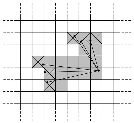
Figure 1.
The relationship between the scanning point and the grid points.
2.2. IMU-Aided Scan-to-Map Matching
In the scan-to-map matching process, which is also called the front end, high-precision initial pose estimates can improve the accuracy of matching, which is calculated by the IMU mechanization algorithm in this paper. The main task of IMU mechanization is to use the output values of the gyroscope and accelerometer to calculate the navigation parameter through the position, velocity, and attitude update algorithms, which is a process of recursive calculation. The speed differential equation under the navigation coordinate system can be expressed as
where is the projected velocity under the coordinate system of the coordinate system (that is, the ground speed) relative to the coordinate system ; is the specific force outputted by the accelerometer; is the Coriolis acceleration; is the centripetal acceleration of the carrier relative to the Earth; and is the acceleration of gravity. The quaternion equation for positional update can be expressed as
where the position quaternion at time is known information and , can be calculated as
where is the rotation vector of the ECEF (Earth-Centered, Earth-Fixed) coordinate system and navigation coordinate system from time to time . Thus, we can get a relatively correct position from the IMU mechanization algorithm, which can narrow the search window of the LiDAR scan-to-map matching. Using this method, we can properly solve the problem of data association and there is no need for an exhaustive pose search.
The Gauss–Newton method is utilized to find the optimal match between the current LiDAR scan data and the map that has been constructed. Given an occupancy grid map obtained from previous LiDAR scan data and the initial pose (provided by IMU) of the current LiDAR scan data, we seek to find the optimal rigid transformation to minimize the occupancy probability residual:
where transforms point from the LiDAR scan coordinate system to the map coordinate system; returns the occupancy probability at the coordinate and is a smooth version of the occupancy probability values in the map. We use bilinear interpolation here to calculate the occupancy probability value , and the gradient is computed as
The four closest integer coordinates around the position are needed to calculate the gradient during the calculation because the discontinuous nature of the occupancy grid map makes it impossible to calculate the derivative directly and will limit the calculation accuracy.
2.3. Control-Network-Aided SLAM Back-End Optimization
The scan-to-map matching strategy adopted by the front end can reduce the accumulation of positioning errors and mapping errors to a certain extent. However, as the mapping area expands, its positioning accuracy and mapping accuracy will gradually decrease. To further solve this problem, back-end optimization is performed by using the relative constraint information between discontinuous frames, which is called loop closure, to suppress the accumulation of errors. Submap-based back-end optimization is applied in this scheme. It selects some scans in one submap to match the other submaps by scan-to-map matching to obtain the relative pose between the submaps, which is the most time-consuming process. If we find a good match between submaps, the corresponding relative constraint is added to the back-end optimization problem to eliminate the cumulative error. Back-end optimization can also be expressed as a nonlinear least square problem that can be written as
in which the submap poses and the scan poses in the world coordinate system are optimized by relative constraints; indicates the relative pose relationship between submap and LiDAR scan ; and represents the covariance matrix. The residual E is calculated as
and in (8) is a loss function to reduce the effect of outliers since a wrong constraint might be added to the back-end optimization problem during the process of loop closure detection.
The absolute coordinate information of the control network can be treated as position constraint information to the submap too, which needs to be considered in the process of back-end optimization. Firstly, a reasonable control network is laid out according to the actual situation of the survey area, and the control network is measured using a total station to establish an absolute coordinate system. During the data acquisition process, the LiDAR scanning center can be aligned with a control point on the motion path. At the same time, the aligned scanning frame data are marked with a special number by the data collection software. The residual of such constraints can be computed as
where are the pose of the marked scan frame in the absolute control network coordinate system and in the submap coordinate system of SLAM, respectively; describes the transformation relationship between the absolute control network coordinate system and the submap coordinate system of SLAM.
2.4. Distributed Indoor Mapping Based on Control-Network-Aided SLAM
According to Section 2.3, the mapping results of control-network-aided SLAM can be converted into the coordinate system defined by the control point coordinates. If all the control points are measured uniformly, then the mapping area can be divided into many small blocks for mapping. The results of these distributed mappings will be in a unified coordinate system without matching each other to obtain their relative positions, which can greatly simplify the mapping process and improve the mapping efficiency. Figure 2 illustrates the process of the distributed indoor mapping scheme based on control-network-aided SLAM.
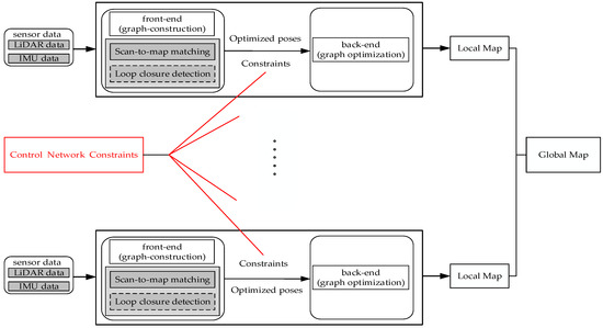
Figure 2.
Distributed indoor mapping based on control-network-aided Simultaneous Localization and Mapping (SLAM) (LiDAR (Light Detection and Ranging) and IMU (International Mathematical Union)).
3. Field Tests and Results
3.1. LiDAR/IMU Integrated System Overview
As shown in Figure 3, a LiDAR/IMU integrated hardware system was designed and built; it contained an Xsens MTi-G IMU and Hokuyo UTM-30LX-EW LiDAR. The data from the LiDAR and IMU were transmitted to the laptop through the network port and USB port, respectively. The Xsens MTi-G IMU is a MEMS-level device and its sampling frequency is 200HZ; other major performance indicators are as follows: gyroscope bias is 200 degrees/h, accelerometer bias is 2000 mGal. UTM-30LX-EW LiDAR operates at 40 Hz, its field of view is 270 degrees with an angular resolution of 0.25 degrees, and its maximum effective range is 30 m with a range accuracy of ±30 mm at 0.1~10 m and ±50 mm at 10~30 m.
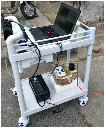
Figure 3.
The LiDAR/IMU integrated system.
3.2. Field Test Overview
A series of field tests were designed and carried out in a large indoor parking lot (about 10,000 square meters) to evaluate the performance of the distributed indoor mapping scheme based on control-network-aided SLAM. The experimental environment is shown in Figure 4. In the parking lot, we designed and laid out a control network that contained 35 control points, and the coordinates of the control points were measured using a total station. The parking lot was divided into four independent mapping blocks, as shown in Figure 5. The LiDAR/IMU integrated hardware platform was mounted on a mobile platform. During the data acquisition, when the mobile hardware platform moved near a control point, we carefully adjusted the movement of the mobile hardware platform to align the LiDAR scanning center with the control point, which means that the origin of the platform coordinate system coincided with the control point. Then, the aligned scanning frame data were marked with a special number by the data collection software. To fully assess the accuracy and effectiveness of the proposed algorithm, we performed corresponding field tests and compared the mapping result with a high-precision reference map produced using a ground laser scanner to evaluate the relative accuracy and absolute accuracy of the mapping result, and we evaluated the impact of different numbers of control points on the accuracy of the mapping result. Accuracy assessment of the algorithm was achieved by evaluating the accuracy of selected main feature points (such as corners or some obvious fixed object). The high-precision reference map produced by the FARO Focus3D X130 HDR ground laser scanner and the map produced by our algorithm could both be imported to ArcGIS software, where we could manually extract the coordinates of the common feature points for accuracy assessment.
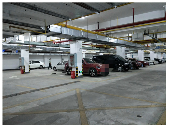
Figure 4.
Experimental site local environment.
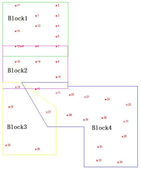
Figure 5.
Control network distribution.
3.3. Evaluation of Relative Accuracy and Absolute Accuracy
Relative accuracy indicates the accuracy of the relative positional relationship between objects inside the map, which is an important indicator for evaluating the consistency of the mapping result in one SLAM process. We selected a certain number of feature points with the same name from the high-precision reference map and our map, then calculated the coordinate conversion parameters between the two sets of coordinate systems, and finally calculated the RMS (Root Mean Square) of the transformed coordinate residuals to evaluate the relative accuracy. We chose Block 1 to evaluate the relative accuracy of the control-network-aided SLAM. The mapping results are shown in Figure 6. The mapping result MAP_I is the result of adding the control network constraints to the back-end optimization. The mapping result MAP_II was constructed without considering any constraints. Loop closure was not considered in MAP_I or MAP_II. Table 1 shows the RMS of the coordinate error of the selected common feature points. The RMS values of the coordinate error of the selected common feature points of MAP_I and MAP_II were 0.08 m and 0.16 m, respectively. The mapping results show that adding control network constraints can effectively eliminate the cumulative error to improve the accuracy of the mapping result; the relative accuracy was improved by 49.8% compared to that of MAP_II. The accuracy of MAP_I reached the centimeter level without considering loop detection, which means that we can improve the accuracy of SLAM where it is difficult to detect loop closure by utilizing the method of adding control network constraints. The reason for this is that control point information includes the relative constraints between the submaps, which is similar to loop closure and can improve the accuracy of SLAM.
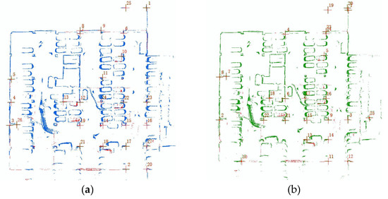
Figure 6.
(a) MAP_ I: Mapping result of adding control network constraints; (b) MAP_III: Mapping result without control network or loop closure constraints.

Table 1.
RMS (Root Mean Square) comparison of different mapping results.
Absolute accuracy indicates the consistency of the mapping results in different SLAM processes in the distributed mapping, which can be analyzed by the difference between the mapping results and the reference map in the control network coordinate system. It also refers to the accuracy of map stitching in various parts after distributed mapping. In order to analyze the absolute accuracy, the high-precision reference maps were converted into the control network coordinate system using target balls, which were placed artificially with known coordinates. The absolute position error of the same named points in the two maps which were in a unified coordinate system (high-precision reference map and MAP_I in Section 3.3) was calculated to analyze the absolute accuracy, which determined the accuracy of map stitching. We separately selected common feature points, such as corners or other obvious fixed objects, from MAP_I and the converted high-precision reference map, and then calculated the RMS of the absolute position errors to indicate the absolute accuracy. The RMS of the absolute position error of the selected common feature points was 0.13 m, which indicates that the mapping results of different blocks can achieve good splicing.
3.4. Evaluation of the Influence of Control Point Density
In order to assess the influence of the density of control points on the relative and absolute accuracy of the mapping result, we compared the accuracy of the mapping results by adding different numbers of control points distributed evenly to assess the effect of density of control points on the mapping result. The control points in Block 1 are shown in Figure 7. The RMS values of the relative and absolute accuracy are shown in Table 2. These show that the density of control points has a significant impact on the accuracy of the mapping result: there is a trend that as the density of control points increases, the accuracy of the mapping increases accordingly. The relative accuracy and absolute accuracy of the mapping result were increased by 41.86% and 31.19% when the number of control points increased from 4 to 8. However, the improvement in mapping accuracy was not so obvious when the number of control points increased from 8 to 12. The results indicate that the number of control points does have an influence on the accuracy of the mapping result, but when the control points reach a certain number, the accuracy of the mapping result is not increased significantly by adding more control points. In practical applications, we need to reasonably choose the number of control points and control network structure according to the actual situation to achieve reasonable accuracy.

Figure 7.
Control point distribution in Block 1.

Table 2.
RMS comparison of different mapping results (adding different numbers of control points).
3.5. Evaluation of Distributed Indoor Mapping
To further analyze the feasibility of the distribution mapping scheme, the control-network-aided SLAM was utilized to obtain the other parts (Blocks 2–4) of the parking lot. The LiDAR/IMU integrated system mounted on a vehicle started from any position in any block and completed the mapping separately. As we added control network constraints to the back end in the four mapping tasks, the mapping results of the four blocks are all in the absolute coordinate system of the control network. The distributed SLAM results are shown in Figure 8. We can see that the overlap between the distributed SLAM results of adjacent blocks is almost coincident, which indicates the feasibility of the distributed mapping scheme. We further analyzed the stitching accuracy of the distributed mapping results, which is shown in Table 3. We selected 56 (28 pairs) common feature points from the overlapping parts of different mapping results and calculated the RMS of the position error as 0.14m. This is basically consistent with the absolute accuracy analyzed in Section 3.3.
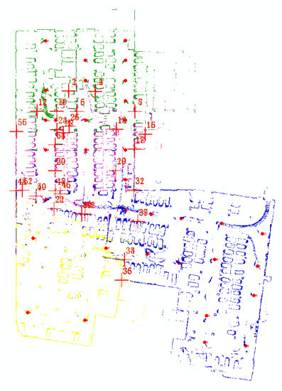
Figure 8.
Distributed mapping result (MAP_VII).

Table 3.
Stitching accuracy of distributed mapping results.
4. Discussion
On the basis of IMU-aided SLAM, the further introduction of control network information can effectively improve the relative accuracy of mapping. The control point information can introduce absolute correction information into the SLAM process, which can improve the relative accuracy of SLAM. At the same time, the introduction of control point information into the SLAM back end can be used to convert the mapping results to the global frame where the control point coordinates are located, so that large-scale mapping can be divided into multiple small mapping areas. The absolute accuracy was calculated by comparing the feature points of the mapping result and the reference map and reached 0.13 m, which is similar to the stitching accuracy in the distributed mapping process. Existing distributed mapping methods can also perform distributed mapping well, but they require relative matching between maps to achieve map stitching. When the relative matching is accurate, its accuracy may be better than that of our scheme. Our proposed scheme is a simplified scheme which can omit the time-consuming process of relative matching to improve efficiency with a limited loss of accuracy and obtain viable distributed mapping results. The results obtained by our scheme can also provide a good prior value for relative map matching.
5. Conclusions
In this paper, we proposed a distributed indoor mapping scheme based on control-network-aided SLAM to solve the problem of mapping for large-scale environments. Compared to other SLAM-based solutions with mapping results in different local coordinate systems, our scheme may be more efficient, without the need to transform all results into a unified coordinate system through a map-matching algorithm. The experimental results show that the relative accuracy can reach 0.08 m, which is an improvement by 49.8% compared to the SLAM result without any constraints. Moreover, the absolute accuracy can reach 0.13 m and the stitching accuracy can reach 0.14 m, which proves that the mapping results of different SLAM processes using this method can be stitched directly without a matching process.
Author Contributions
J.T. and C.Q. contributed SLAM algorithm materials and analyzed the feasibility of the scheme, analyzed the data, and wrote the paper; J.W. conceived and designed the experiments; All authors have read and agreed to the published version of the manuscript.
Funding
This study was financially supported by the National Key Research and Development Program (No. 2016YFB0502202 and 2016YFB0501803) and supported by the Fundamental Research Funds for the Central Universities (No. 2042018KF00242).
Conflicts of Interest
The authors declare no conflict of interest.
References
- Gao, R.; Ye, F.; Luo, G.; Cong, J. Indoor map construction via mobile crowdsensing. In Smartphone-Based Indoor Map Construction; Springer: Berlin/Heidelberg, Germany, 2018; pp. 3–30. [Google Scholar]
- Klepeis, N.E.; Nelson, W.C.; Ott, W.R.; Robinson, J.P.; Tsang, A.M.; Switzer, P.; Behar, J.V.; Hern, S.C.; Engelmann, W.H. The national human activity pattern survey (NHAPS): A resource for assessing exposure to environmental pollutants. J. Expo. Sci. Environ. Epidemiol. 2001, 11, 231–252. [Google Scholar] [CrossRef] [PubMed]
- Google Indoor Maps Availability. Available online: http://support.google.com/gmm/bin/answer.py?hl=en&answer=1685827 (accessed on 5 January 2020).
- Chen, Y.; Tang, J.; Jiang, C.; Zhu, L.; Lehtomäki, M.; Kaartinen, H.; Kaijaluoto, R.; Wang, Y.; Hyyppä, J.; Hyyppä, H.; et al. The accuracy comparison of three simultaneous localization and mapping (SLAM)-Based indoor mapping technologies. Sensors 2018, 18, 3228. [Google Scholar] [CrossRef] [PubMed]
- Zlatanova, S.; Sithole, G.; Nakagawa, M.; Zhu, Q. Problems in indoor mapping and modelling. In Proceedings of the Acquisition and Modelling of Indoor and Enclosed Environments 2013, Cape Town, South Africa, 11–13 December 2013; ISPRS Archives Volume XL-4/W4. [Google Scholar]
- Tang, J.; Chen, Y.; Niu, X.; Wang, L.; Chen, L.; Liu, J.; Shi, C.; Hyyppä, J. LiDAR scan matching aided inertial navigation system in GNSS-denied environments. Sensors 2015, 15, 16710–16728. [Google Scholar] [CrossRef] [PubMed]
- Chen, L.; Pei, L.; Kuusniemi, H.; Chen, Y.; Kröger, T.; Chen, R. Bayesian fusion for indoor positioning using bluetooth fingerprints. Wirel. Pers. Commun. 2013, 70, 1735–1745. [Google Scholar] [CrossRef]
- Li, J.; Zhong, R.; Hu, Q.; Ai, M. Feature-based laser scan matching and its application for indoor mapping. Sensors 2016, 16, 1265. [Google Scholar] [CrossRef] [PubMed]
- Kohlbrecher, S.; von Stryk, O.; Meyer, J.; Klingauf, U. A flexible and scalable slam system with full 3d motion estimation. In Proceedings of the 2011 IEEE International Symposium on Safety, Security, and Rescue Robotics, Kyoto, Japan, 1–5 November 2011; pp. 155–160. [Google Scholar]
- Grisetti, G.; Stachniss, C.; Burgard, W. Improved techniques for grid mapping with rao-blackwellized particle filters. IEEE Trans. Robot. 2007, 23, 34. [Google Scholar] [CrossRef]
- Vincent, R.; Limketkai, B.; Eriksen, M. Comparison of indoor robot localization techniques in the absence of GPS. In Detection and Sensing of Mines, Explosive Objects, and Obscured Targets XV; International Society for Optics and Photonics: Bellingham, WA, USA, 2010; p. 76641Z. [Google Scholar]
- Hess, W.; Kohler, D.; Rapp, H.; Andor, D. Real-time loop closure in 2D LIDAR SLAM. In Proceedings of the 2016 IEEE International Conference on Robotics and Automation (ICRA), Stockholm, Sweden, 16–21 May 2016; pp. 1271–1278. [Google Scholar]
- Zhen, W.; Scherer, S. A unified 3D mapping framework using a 3D or 2D LiDAR. arXiv 2018, arXiv:1810.12515. [Google Scholar]
- Xie, X.; Yu, Y.; Lin, X.; Sun, C. An EKF SLAM algorithm for mobile robot with sensor bias estimation. In Proceedings of the 2017 32nd Youth Academic Annual Conference of Chinese Association of Automation (YAC), Hefei, China, 19–21 May 2017; pp. 281–285. [Google Scholar]
- Zhang, T.; Wu, K.; Song, J.; Huang, S.; Dissanayake, G. Convergence and consistency analysis for a 3-D Invariant-EKF SLAM. IEEE Robot. Autom. Lett. 2017, 2, 733–740. [Google Scholar] [CrossRef]
- Montemerlo, M. A Factored Solution to the Simultaneous Localization and Mapping Problem with Unknown Data Association. Ph.D. Thesis, Carnegie Mellon University, Pittsburgh, PA, USA, 2003. [Google Scholar]
- Grisetti, G.; Kummerle, R.; Stachniss, C.; Burgard, W. A tutorial on graph-based SLAM. IEEE Intell. Transp. Syst. Mag. 2010, 2, 31–43. [Google Scholar] [CrossRef]
- Wen, J.; Qian, C.; Tang, J.; Liu, H.; Ye, W.; Fan, X. 2D LiDAR SLAM back-end optimization with control network constraint for mobile mapping. Sensors 2018, 18, 3668. [Google Scholar] [CrossRef] [PubMed]
- Li, J.; Zhan, H.; Chen, B.M.; Reid, I.; Lee, G.H. Deep learning for 2D scan matching and loop closure. In Proceedings of the 2017 IEEE/RSJ International Conference on Intelligent Robots and Systems (IROS), Vancouver, BC, Canada, 24–28 September 2017; pp. 763–768. [Google Scholar]
- Stachniss, C.; Thrun, S.; Leonard, J.J. Simultaneous Localization and Mapping. In Springer Handbook of Robotics; Springer: Berlin/Heidelberg, Germany, 2016. [Google Scholar]
- Aulinas, J.; Petillot, Y.R.; Salvi, J.; Lladó, X. The slam problem: A survey. CCIA 2008, 184, 363–371. [Google Scholar]
- Fox, D.; Ko, J.; Konolige, K.; Limketkai, B.; Schulz, D.; Stewart, B. Distributed multirobot exploration and mapping. Proc. IEEE 2006, 94, 1325–1339. [Google Scholar] [CrossRef]
- Howard, A. Multi-robot simultaneous localization and mapping using particle filters. Int. J. Robot. Res. 2006, 25, 1243–1256. [Google Scholar] [CrossRef]
- Carpin, S. Fast and accurate map merging for multi-robot systems. Auton. Robot. 2008, 25, 305–316. [Google Scholar] [CrossRef]
- Carlone, L.; Ng, M.K.; Du, J.; Bona, B.; Indri, M. Simultaneous localization and mapping using rao-blackwellized particle filters in multi robot systems. J. Intell. Robot. Syst. 2011, 63, 283–307. [Google Scholar] [CrossRef]
- Howard, A.; Parker, L.E.; Sukhatme, G.S. The SDR experience: Experiments with a large-scale heterogeneous mobile robot team. In Experimental Robotics IX; Springer: Berlin/Heidelberg, Germany, 2006; pp. 121–130. [Google Scholar]
- Hidayat, F.; Trilaksono, B.; Hindersah, H. Distributed multi robot simultaneous localization and mapping with consensus particle filtering. In Journal of Physics: Conference Series; IOP Publishing: Bristol, UK, 2017; p. 012003. [Google Scholar]
- Egodagamage, R.; Tuceryan, M. Distributed monocular SLAM for indoor map building. J. Sens. 2017, 2017, 6842173. [Google Scholar] [CrossRef]
- Zou, D.; Tan, P. Coslam: Collaborative visual slam in dynamic environments. IEEE Trans. Pattern Anal. Mach. Intell. 2013, 35, 354–366. [Google Scholar] [CrossRef] [PubMed]
- Hening, S.; Ippolito, C.A.; Krishnakumar, K.S.; Stepanyan, V.; Teodorescu, M. 3D LiDAR SLAM Integration with GPS/INS for UAVs in Urban GPS-Degraded Environments. In Proceedings of the AIAA Information Systems-AIAA Infotech @ Aerospace, Grapevine, TX, USA, 9–13 January 2017. [Google Scholar]
- Qian, C.; Liu, H.; Tang, J.; Chen, Y.; Kaartinen, H.; Kukko, A.; Zhu, L.; Liang, X.; Chen, L.; Hyyppä, J. An integrated GNSS/INS/LiDAR-SLAM positioning method for highly accurate forest stem mapping. Remote Sens. 2017, 9, 3. [Google Scholar] [CrossRef]
- Shamseldin, T.; Manerikar, A.; Elbahnasawy, M.; Habib, A. SLAM-based Pseudo-GNSS/INS localization system for indoor LiDAR mobile mapping systems. In Proceedings of the IEEE/ION Position, Location & Navigation Symposium, Monterey, CA, USA, 23–26 April 2018; IEEE: Piscataway, NJ, USA, 2018. [Google Scholar]
- Kudo, T.; Miura, J. Utilizing WiFi signals for improving SLAM and person localization. In Proceedings of the 2017 IEEE/SICE International Symposium on System Integration (SII), Taipei, Taiwan, 11–14 December 2017; IEEE: Piscataway, NJ, USA, 2017; pp. 487–493. [Google Scholar]
- Available online: https://geosys.org/?page_id=36366 (accessed on 14 February 2020).
- Homm, F.; Kaempchen, N.; Ota, J.; Burschka, D. Efficient occupancy grid computation on the GPU with lidar and radar for road boundary detection. In Proceedings of the 2010 IEEE Intelligent Vehicles Symposium, San Diego, CA, USA, 21–24 June 2010; pp. 1006–1013. [Google Scholar]
© 2020 by the authors. Licensee MDPI, Basel, Switzerland. This article is an open access article distributed under the terms and conditions of the Creative Commons Attribution (CC BY) license (http://creativecommons.org/licenses/by/4.0/).