Article

Optimal Control Approach to Lambert’s Problem and Gibbs’ Method

Department of Aerospace Engineering, Sejong University, Seoul 05006, Korea
*
Author to whom correspondence should be addressed.
Appl. Sci. 2020, 10(7), 2419; https://doi.org/10.3390/app10072419
Submission received: 18 February 2020 / Revised: 24 March 2020 / Accepted: 29 March 2020 / Published: 1 April 2020

Abstract

:
This paper presents the optimal control approach to solve both Lambert’s problem and Gibbs’ method, which are commonly used for preliminary orbit determination. Lambert’s problem is reinterpreted with Hamilton’s principle and is converted to an optimal control problem. Various extended Lambert’s problems are formulated by modifying the weighting and constraint settings within the optimal control framework. Furthermore, Gibbs’ method is also converted to an extended Lambert’s problem with two position vectors and one orbit energy with the help of the proposed orbital energy computation algorithm. The proposed extended Lambert’s problem and Gibbs’ method are numerically solved with the Lobatto pseudospectral method, and their accuracies are verified by numerical simulations.

1. Introduction

Lambert’s problem and Gibbs’ method are both preliminary orbit determination methods. Lambert’s problem is a two-point boundary value problem (TPBVP) that finds the trajectory in a two-body orbit with two position vectors at a given time of flight. Gibbs’ method calculates the velocity of the middle position using three position vectors given at three successive times.
Many methods were proposed in literature to solve Lambert’s problem. Shen and Tsiotras [1] calculated the multiple-revolution Lambert’s solution using Battin’s method. Guibout and Scheeres [2] solved the TPBVP using the Hamilton–Jacobi theory in conjunction with canonical transformation. Dario Izzo [3] applied the Householder iterative method as a simple approximation. Avanzini [4] solved Lambert’s problem using the Newton–Raphson iteration scheme. Bando and Yamakawa [5] showed that the solution to Lambert’s problem can be obtained directly by minimizing the action integral by Hamilton’s principle. They also showed that Lambert’s problem can be transformed to an optimal control problem. On the other hand, only a few solutions are found in literature for Gibbs’ method and all of them are geometric-based approaches [6,7].
In this paper, we propose an alternative method for solving both Lambert’s problem and Gibbs’ method with the same optimal control framework. Lambert’s problem is reinterpreted with Hamilton’s principle and is converted to an optimal control problem with a similar method used in [2,5]. Furthermore, we generalize Lambert’s problem to the extended Lambert’s problem using various weighting, constraint, and potential energy settings. The proposed extended Lambert’s problems include the orbit determination methods with elliptical, parabolic, and hyperbolic orbits and the initial-position-and-final-velocity-specified orbits. Two important extended Lambert’s problems are also considered. One is the optimal control formulation of Gibbs’ method for orbit determination and the other is the Lambert’s problem under J2 perturbation. Gibbs’ method is converted to an extended Lambert’s problem using two position vectors and one orbital energy as boundary conditions; this results in a non-geometric-based Gibbs’ solution, unlike the previous solutions in the existing literature. Gibbs’ method is solved along with the proposed orbital energy computation algorithm. A new approach to solving Lambert’s problem under J2 perturbation is presented by modifying the potential energy term in our optimal control framework. For numerically solving the various extended Lambert’s problems, the Lobatto pseudospectral method (LPM) is used in this paper.
This paper is organized as follows: in Section 2, Lambert’s problem is explained and it is shown that it can be formulated as an optimal control problem; in Section 3, various extended Lambert’s problems are presented using different weighting, constraint, and potential energy settings within the optimal control framework; Section 4 proposes an alternative Gibbs’ solution using an extended Lambert’s problem along with the proposed orbit energy calculation algorithm; in Section 5, numerical simulations are performed to demonstrate the validity of the proposed optimal control approach and a brief introduction of LPM is given as a numerical solver for optimal control; finally, conclusions are given in Section 6.

2. Optimal Control Approach to Lambert’s Problem

2.1. Lambert’s Problem

Lambert’s problem is a TPBVP of solving the following orbital differential equation of motion, which is derived from the two-body problem [6,8]:
d 2 r d t 2 + μ ( r r ) 3 r = 0
given the initial and final position vectors, r ( t 1 ) = r 1 , r ( t 2 ) = r 2 at the given initial and final times, t 1 and t 2 . In Equation (1), μ is the gravitational constant, and r is the position vector of one object relative to another object. As stated above, many methods have been proposed to solve this problem.

2.2. Optimal Control Approach

This section illustrates that Lambert’s problem can be reformulated as an optimal control problem. We adopt the method shown in [9], which starts with defining the fictitious “plant” as the following:
d r d t = r ˙ = v
where the velocity vector v is regarded as the fictitious “input”. To find the trajectories of the motion of the fictitious plant, Hamilton’s principle says that the following cost function should be minimized:
J = t 1 t 2 T ( r , v ) U ( r ) d t = t 1 t 2 L ( r , v ) d t
where [ t 1 , t 2 ] is the time interval of interest, T is the kinetic energy, U is the potential energy, and L is the Lagrangian. For the two-body problem, the kinetic and potential energies should be defined as follows:
T = 1 2 v v ,   U = μ r r .
Meanwhile, we propose that the cost function of Equation (3) be generalized, as follows, for the context of the optimal control problem:
J = ϕ ( r ( t 2 ) , t 2 ) + t 1 t 2 1 2 v v + μ r r d t
where ϕ ( r ( t 2 ) , t 2 ) is the final weighting function, which depends on the final position and time. Then, the optimal control problem is to find the “input” v that drives the plant of Equation (2) so that the cost function of Equation (5) is minimized and the following constraint equation is satisfied:
ψ ( r ( t 1 ) , t 1 , r ( t 2 ) ,   t 2 ) = 0
The solution to this optimal control problem can be found in the literature [9,10]; the necessary conditions for optimality are given as follows:
r ˙ = H λ = v
λ ˙ = H r = μ ( r r ) 3   r
0 = H v = v + λ
where λ is the Lagrange costate multiplier of the dynamics and H is the Hamiltonian, which is defined as:
H = 1 2 v v + μ r r + λ v
The constraints and the boundary conditions are given as follows:
ψ ( r ( t 1 ) , t 1 ,   r ( t 2 ) ,   t 2 ) = 0
( ϕ r + ( ψ r ) T p λ ) t 1 T   d r ( t 1 ) + ( ϕ t + ( ψ t ) T p + H ) t 1 d t 1 = 0
( ϕ r + ( ψ r ) T p λ ) t 2 T   d r ( t 2 ) + ( ϕ t + ( ψ t ) T p + H ) t 2 d t 2 = 0
where p is the Lagrange static multiplier.
Equations (7)–(9) yield the equation of the two-body problem—Equation (1)—and the Hamiltonian of Equation (10) becomes:
H = 1 2 v v + μ r r =
which is nothing more than the negative value of orbital energy . Since the Hamiltonian of Equation (10) is a time-invariant function, the Hamiltonian or negative orbital energy becomes constant, which is a well-known result from classical orbital mechanics.
Now, if the following conditions are imposed on Equations (5) and (6):
ϕ ( r ( t 2 ) , t 2 ) = 0
r ( t 1 ) = r 1 , r ( t 2 ) = r 2 , t 1 , t 2   g i v e n
then the optimal control problem given in Equations (2), (5), and (6) is mathematically equivalent to the standard Lambert’s problem of Equation (1).
The process of reformulating Lambert’s problem to an optimal control problem, as illustrated above, suggests that various extended Lambert’s problems can be generated by using different weighting and constraint settings, which are further discussed in Section 3.

3. Extended Lambert’s Problem

Lambert’s problem can be extended to various formulations using different weighting and constraint settings. This section suggests some extensions to the orbit determination methods with elliptical, parabolic, hyperbolic, and the initial-position-and-final-velocity-specified orbits. An extension to Gibbs’ method is discussed in Section 4.

3.1. The Energy-Specified Lambert’s Problem

Consider that the following conditions are imposed on Equations (5) and (6):
ϕ ( r ( t 2 ) , t 2 ) = s e t t 2
r ( t 1 ) = r 1 , r ( t 2 ) = r 2
t 1   g i v e n , t 2   f r e e
where s e t is a specified orbital energy, which may be an orbit design parameter; Equation (12) is automatically satisfied and Equation (13) is reduced to:
( ϕ t + H ) t 2 = s e t + H ( t 2 ) = 0
Since the Hamiltonian H or the negative value of orbital energy is constant, Equation (16) means that the optimal trajectory satisfies the conditions of Equation (15) and has a constant energy level of s e t . Therefore, the optimal control problem given above is mathematically equivalent to Equation (1), with the following boundary conditions:
r ( t 1 ) = r 1 , r ( t 2 ) = r 2
t 1   g i v e n , t 2   f r e e , = s e t
Equations (1) and (17) define the energy-specified Lambert’s problem, which is a two-point boundary value problem with the given initial position vector r ( t 1 ) = r 1 at the given time t 1 and the given final position vector r ( t 2 ) = r 2 at some time of t 2 along with the given orbital energy of s e t .
The energy-specified Lambert’s problem can be used in orbit design, which connects two positions with elliptical, parabolic, and hyperbolic orbits with various energy levels. In Section 5.2, some numerical simulations are performed to demonstrate the feasibility of the proposed energy-specified Lambert’s problem.

3.2. The Velocity-Specified Lambert’s Problem

If the following conditions are imposed on Equations (5) and (6):
ϕ ( r ( t 2 ) , t 2 ) = v 2 r ( t 2 )
r ( t 1 ) = r 1 , r ( t 2 )   f r e e
t 1 , t 2 g i v e n
where v 2 is a final velocity of orbit at t = t 2 which may be an orbit design parameter, then Equation (12) is automatically satisfied and Equation (13) is reduced to:
( ϕ r λ ) t 2 = v 2 λ ( t 2 ) = 0
Since λ ( t 2 ) = v ( t 2 ) from Equations (9) and (20) means that v ( t 2 ) = v 2 the optimal control problem given above is mathematically equivalent to Equation (1) with the following boundary conditions:
r ( t 1 ) = r 1 , v ( t 2 ) = v 2
t 1 , t 2   g i v e n
Equations (1) and (20) define the velocity-specified Lambert’s problem, which is a two-point boundary value problem with the given initial position vector r ( t 1 ) = r 1 at the given time t 1 and the given final velocity vector v ( t 2 ) = v 2 at the given time t 2 . Although the application of this problem set cannot readily be revealed, the velocity-specified Lambert’s problem clearly extends the standard Lambert’s problem to more general boundary conditions.

3.3. Lambert’s Problem under J2 Perturbation

If J2 perturbation is taken into account, the potential energy term in Equation (4) should be modified as follows [8]:
U = μ r r μ J 2 R 2 2 r r 3 ( 1 3 z 2 r r )
where R is the mean equatorial radius of the Earth, J 2 is the second zonal harmonic coefficient for the Earth, and z is the Z-axis component of the position vector in the Earth Centered Inertial (ECI) frame.
Then, the Lambert’s problem under J2 perturbation can be reformulated to an optimal control problem given as:
a r g   m i n v t 1 t 2 1 2 v v + μ r r + μ J 2 R 2 2 r r 3 ( 1 3 z 2 r r )   d t
r ˙ = v
r ( t 1 ) = r 1 , r ( t 2 ) = r 2
t 1 , t 2   g i v e n

4. Optimal Control Approach to Gibbs’ Method

4.1. Gibbs’ Method

The energy-specified Lambert’s problem can be used in orbit design, which connects two positions with elliptical, parabolic, and hyperbolic orbits with various energy levels. Gibbs’ method calculates the velocity at the second observed position using three observed position vectors r 1 , r 2 and r 3 at three successive times t 1 , t 2 and t 3 ( t 3 > t 2 > t 1 ), assuming that the object is in a two-body orbit. Note that the three position vectors are supposed to be coplanar. Gibbs’ solutions are rarely found in the literature and all of them are purely geometric-based approaches [6,7].
In this section, a novel Gibbs’ solution is presented, using the proposed energy-specified Lambert’s problem. Gibbs’ method is formulated as follows:
d 2 r d t 2 + μ ( r r ) 3 r = 0
r ( t 1 ) = r 1 , r ( t 2 ) = r 2 , r ( t 3 ) = r 3
t 1   g i v e n , t 2 , t 3   f r e e
A mathematically equivalent energy-specified Lambert’s problem to Equation (23) can be given as:
a r g   m i n v   s e t t 2 + t 1 t 2 1 2 v v + μ r r   d t
r ˙ = v
r ( t 1 ) = r 1 , r ( t 2 ) = r 2
t 1   g i v e n , t 2   f r e e , s e t   g i v e n
where r ( t 1 ) , r ( t 2 ) may be replaced by any two position vectors of the three given position vectors. To solve this problem, the orbital energy s e t corresponding to the three given position vectors must be determined. In the next subsection, a novel orbital energy computation algorithm is presented for this purpose.

4.2. Orbital Energy Computation

To find the orbital energy as a function of the given three position vectors, we start with orbit equations, as follows:
r 1 = p 1 + e   c o s θ 1
r 2 = p 1 + e   c o s ( θ 1 + Δ θ 12 )
r 3 = p 1 + e   c o s ( θ 1 + Δ θ 13 )
where e is the eccentricity, p is the semi-latus rectum, θ 1 is the true anomaly of position vector r 1 , and the changes in the true anomalies Δ θ 12 and Δ θ 13 are calculated as illustrated in Figure 1 by:
Δ θ 12 = c o s 1 r 1 r 2 r 1 r 2
Δ θ 13 = c o s 1 r 1 r 3 r 1 r 3
where
r 1 = r 1 r 1 , r 2 = r 2 r 2 , r 3 = r 3 r 3
and Δ θ 23 = Δ θ 13 Δ θ 12 .
Making use of the trig relationships and substituting Equation (25) into Equations (26) and (27) yield:
p r 2 = 1 + ( p r 1 1 ) c o s   Δ θ 12 e   s i n θ 1 s i n   Δ θ 12
p r 3 = 1 + ( p r 1 1 ) c o s   Δ θ 13 e   s i n θ 1 s i n   Δ θ 13
Using these equations, p can be found as:
p = s i n   Δ θ 13 s i n   Δ θ 12 s i n   Δ θ 23 ( s i n   Δ θ 13 r 2 s i n   Δ θ 12 r 3 s i n   Δ θ 23 r 1 )
From Equations (26), (30), and (32), the true anomaly can be calculated as follows:
θ 1 = t a n 1 ( e   s i n   θ 1 e   c o s   θ 1 )
Now, with the knowledge of p and θ 1 , the eccentricity becomes:
e = p r 1 1 c o s   θ 1
Finally, the orbital energy can be computed by the following equation:
s e t = μ ( 1 e 2 ) 2 p .
The proposed orbital energy computation algorithm for the given three position vectors is summarized in Table 1.

5. Numerical Simulations

5.1. Lobatto Pseudospectral Method

Generally, optimal control problems are very difficult to find an analytical solution for and, thus, numerical methods are widely used. Many different numerical methods can be found in literature [11,12] and, typically, pseudospectral methods are preferred for their computational efficiency and accuracy. In this paper, LPM is used because LPM can calculate the control values at both end points, which is a required property in Lambert’s problem solutions.
In LPM, the continuous-time optimal control problem is transformed to a nonlinear programming (NLP) problem by discretizing the state and control variables of the dynamic equations at Legendre–Gauss–Lobatto (LGL) points; the cost function is approximated using a Gauss quadrature. Since a detailed explanation of LPM can be found easily in literature [11,12], the final results are summarized here as follows.
First, the original time interval where t [ t 1 , t 2 ] is transformed to the time interval where τ [ 1 , 1 ] by the following equation:
τ = 2 t t 2 t 1 t 2 + t 1 t 2 t 1 .
The state and control variables of Equation (2) are approximated in terms of N Lagrange interpolating polynomials as:
r ( τ ) R ( τ ) = i = 1 N R i L i ( τ )
v ( τ ) V ( τ ) = i = 1 N V i L i ( τ )
where R i = R ( τ i ) , V i = V ( τ i ) , and L i ( τ ) is defined as:
L i ( τ ) = k = 1 k i N τ τ k τ i τ k
Next, the dynamic Equation (2) is discretized at the LGL points as:
i = 1 N D j i R i = t 2 t 1 2 V j , j = 1 , , N
where D j i = L ˙ i ( τ j ) is an element of the Lobatto pseudospectral differential matrix. The cost function of Equation (5) is approximated using a Gauss quadrature as:
J = ϕ ( R N , t 2 ) + t 2 t 1 2 i = 1 N w i ( V i T V i 2 + μ R i T R i )
where w i are the LGL weights. Finally, the discretized constraints of Equation (6) are also expressed, as follows:
ψ ( R 1 , t 1 , R N , t 2 ) = 0
The cost function of Equation (40), along with the algebraic constraints of Equations (39) and (41), formulates the converted NLP problem; the solution of this NLP is the approximate solution to the original optimal control problem.

5.2. Extended Lambert’s Problem

A numerical simulation was performed to demonstrate the validity of the proposed optimal control approach to the extended Lambert’s problem. The data used in this simulation were taken from [6]. In the first simulation, the energy-specified Lambert’s problem was considered. The initial position of an Earth satellite was determined to be:
r ( t 1 ) = 5000   ι ^ 1 + 10,000   ι ^ 2 + 2100   ι ^ 3   ( k m )
and after some time, the final position vector was determined to be:
r ( t 2 )   m )   10,000 n   earth   satellite   is   determined   to   be   ,   and   after   one   hour   the   position   vector   is = 14,600   ι ^ 1 + 2500   ι ^ 2 + 7000   ι ^ 3   ( km )
where ι ^ 1 , ι ^ 2 , ι ^ 3 are the unit direction vectors of the ECI frame. The orbital energy was kept as:
s e t = 9.963549   km 2 / s 2
which corresponds to an elliptical orbit. The exact time of flight was determined as:
Δ t = t 2 t 1 = 3600   sec
and the exact initial velocity was determined as:
v ( t 1 ) = 5.992495   ι ^ 1 + 1.925364   ι ^ 2 + 3.245637   ι ^ 3   ( km / s )
This extended Lambert’s problem was solved by the optimal control approach using LPM with the NLP solver ‘fmincon’ in Matlab with 12 LGL points. The time of flight was calculated as:
Δ t ^ = 3600.00023   sec
and the average orbital energy was calculated as:
^ a v e = 9.963598   km 2 / s 2
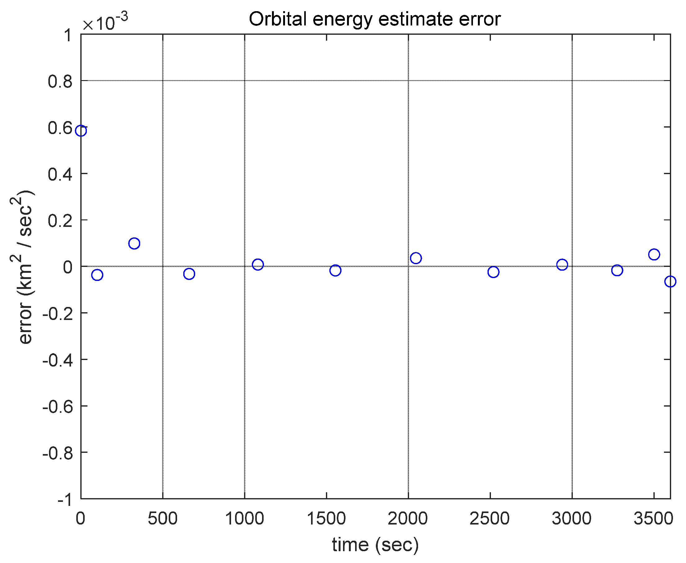
which shows that the proposed optimal control approach calculates the time of flight and the orbital energy very accurately. Figure 2 shows the time history of the orbital energy estimate error, e = s e t ^ ( t ) .
The initial velocity was calculated as:
v ^ ( t 1 ) = 5.992494   ι ^ 1 + 1.925376   ι ^ 2 + 3.245451   ι ^ 3   ( km / s )
and the error was e v = | v ( t 1 ) v ^ ( t 1 ) | = 1.857 × 10 4   ( km / s ) which shows that the proposed optimal control approach accurately produces the Lambert’s solution.
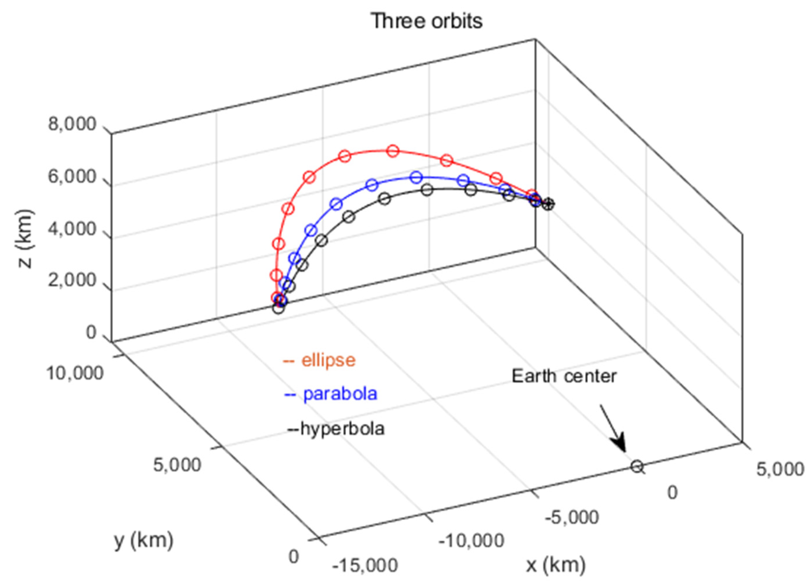
Other simulations were performed with the same initial and final positions, but with different energy levels, such as s e t = 0   km 2 / s 2 and s e t = + 9.96355   km 2 / s 2 , which correspond to parabolic and hyperbolic orbits, respectively. In the case of a parabolic orbit, the time of flight was calculated as Δ t = 2761.3743   sec , while for a hyperbolic orbit, it was Δ t = 2357.0746   sec . Simulation results are presented in Figure 3, which shows elliptical, parabolic, and hyperbolic orbits in the ECI frame with the same initial and final position, respectively.
These simulation results show that the energy-specified Lambert’s problem can provide an alternative orbit design tool in which the orbit connects two points with a specified orbital energy level or a specified orbit shape.
In the next simulation, the velocity-specified Lambert’s problem was solved. In this simulation, the initial position of an Earth satellite was determined to be:
r ( t 1 ) = 5000   ι ^ 1 + 10,000   ι ^ 2 + 2100   ι ^ 3   ( km )
and after one hour the velocity vector was determined to be:
v ( t 2 )   m )   10,000 n   earth   satellite   is   determined   to   be   ,   and   after   one   hour   the   position   vector   is   = 3.312460   ι ^ 1 4.196617   ι ^ 2 0.385288   ι ^ 3   ( km / s )
The exact finial position was given by:
r ( t 2 )   m )   10,000 n   earth   satellite   is   determined   to   be   ,   and   after   one   hour   the   position   vector   is   = 14,600   ι ^ 1 + 2500   ι ^ 2 + 7000   ι ^ 3   ( km ) .
This problem was also solved by the optimal control approach using LPM with 12 LGL points. The final position was calculated as:
r ^ ( t 2 ) = 14599.997136   ι ^ 1 + 2500.001750   ι ^ 2 + 7000.004689   ι ^ 3 ( km )
and the error was e p = | r ( t 2 ) r ^ ( t 2 ) | = 5.766 × 10 3   ( km ) . The final velocity was calculated as:
v ^ ( t 2 ) = 3.312465   ι ^ 1 4.196625   ι ^ 2 0.385275   ι ^ 3   ( km / s )
and the error was e v = | v ( t 2 ) v ^ ( t 2 ) | = 1.546 × 10 5   ( km / s ) Therefore, this simulation result shows again that the proposed optimal control approach accurately produces Lambert’s solutions.
Finally, the >Lambert’s problem under J2 perturbation was considered. The simulation was performed with the same initial and final positions given in Equations (42) and (43), with the flight time of one hour, but with J2 perturbation. Using the shooting method, the corrected initial velocity was calculated as:
v c ( t 1 ) = 5.992105   ι ^ 1 + 1.925528   ι ^ 2 + 3.247763   ι ^ 3   ( km / s )
which yields the final position error of 9.993   cm compared with r ( t 2 ) in Equation (43). This perturbed Lambert’s problem was solved by the optimal control approach using LPM with 12 LGL points. The initial velocity was calculated as:
v ^ c ( t 1 ) = 5.992078   ι ^ 1 + 1.925523   ι ^ 2 + 3.247772   ι ^ 3   ( k m / s )
and the error was e v = | v c ( t 1 ) v ^ c ( t 1 ) | = 2.871 × 10 5   ( km / s ) , which shows that the proposed optimal control approach is a very powerful framework even when solving Lambert’s problem under J2 perturbation.

5.3. Gibbs’ Method

A numerical simulation was performed to demonstrate the validity of the proposed optimal control approach to Gibbs’ method. The data used in the simulation were also taken from [6]. The three position vectors at three successive times are:
r 1   m )   10,000 n   earth   satellite   is   determined   to   be   ,   and   after   one   hour   the   position   vector   is   = 294.3229   ι ^ 1 + 4265.0522   ι ^ 2 + 5986.6720   ι ^ 3   ( km )
r 2   m )     10,000 n   earth   satellite   is   determined   to   be   ,   and   after   one   hour   the   position   vector   is   = 1365.4618   ι ^ 1 + 3637.6479   ι ^ 2 + 6346.7571   ι ^ 3   ( km )
r 3   m )     10,000 n   earth   satellite   is   determined   to   be   ,   and   after   one   hour   the   position   vector   is   = 2940.2717 ι ^ 1 + 2473.7481 ι ^ 2 + 6555.7624 ι ^ 3   ( km )
The exact velocity at the second observed position was determined as:
v 2 = 6.217052   ι ^ 1 4.011651   ι ^ 2 + 1.598927   ι ^ 3   ( km / s )
The exact orbital energy was computed to be:
s e t = 24.912500   ( km 2 / s 2 ) .
Using three position vectors r 1 ,   r 2 and r 3 , the proposed orbital energy computation algorithm yielded some of the orbital elements:
p = 7920   ( k m ) , e = 0.1 , θ 1 = 40 °
and the orbital energy:
= 24.912500   ( km 2 / s 2 )
which are perfectly matched to the exact values, respectively. This problem was solved using the proposed energy specified in Lambert’s problem with five LGL points. The velocity at the second observed position was calculated as:
v ^ ( t 2 ) = 6.217053   ι ^ 1 4.011645   ι ^ 2 + 1.598925   ι ^ 3   ( km / s )
and the error was e v = 6.622 × 10 6   ( km / s ) , which shows that the proposed optimal control approach very accurately produces a Gibbs’ solution. Figure 4 shows the corresponding orbit.

6. Conclusions

The optimal control approach to solving both Lambert’s problem and Gibbs’ method for orbit determination was presented in this paper. Lambert’s problem is reinterpreted with Hamilton’s principle and is converted to an optimal control problem. Various extended Lambert’s problems are also formulated by modifying the weighting and constraint settings, which include the orbit determination methods with elliptical, parabolic, and hyperbolic orbits and the initial-position-and-final-velocity-specified orbits.
Furthermore, it is shown that the proposed optimal control approach is a powerful framework even when solving a Lambert’s problem under J2 perturbation by simply modifying the potential energy term. Gibbs’ method is also converted to an extended Lambert’s problem using two position vectors and one orbital energy with the help of the proposed orbital energy computation algorithm, which results in a non-geometric-based Gibbs’ solution.
The proposed extended Lambert’s problem and Gibbs’ method were numerically solved with the Lobatto pseudospectral method, and their accuracies were verified by numerical simulations.

Author Contributions

Conceptualization, S.P.; methodology, S.P.; software and simulation, M.K. and S.P.; formal analysis, S.P.; writing—original draft preparation, M.K.; writing—review and editing, M.K. and S.P.; supervision, S.P.; funding acquisition, S.P. All authors have read and agreed to the published version of the manuscript.

Funding

This research was supported by the Basic Science Research Program through the National Research Foundation of Korea (NRF) funded by the Ministry of Education (NRF-2016R1D1A1B03934475).

Conflicts of Interest

The authors declare no conflicts of interest.

References

  1. Shen, H.; Tsiotras, P. Using Battin’s Method to Obtain Multiple-Revolution Lambert’s Solutions. Adv. Astronaut. Sci. 2003, 116, 1067–1084. [Google Scholar]
  2. Guibout, V.M.; Scheeres, D.J. Solving Two-Point Boundary Value Problems using the Hamiltonian-Jacobi Theory. In Proceedings of the 2th WSEAS International Conference Applied and Theoretical Mechanics, Venice, Italy, 20–22 November 2006; pp. 174–182. [Google Scholar]
  3. Izzo, D. Revisiting Lambert’s Problem. J. Celest. Mech. Dyn. Astron. 2004, 121, 1–15. [Google Scholar] [CrossRef]
  4. Avanzini, G. A Simple Lambert Algorithm. J. Guid. Control Dyn. 2008, 31, 1587–1594. [Google Scholar] [CrossRef]
  5. Bando, M.; Yamakawa, H. New Lambert Algorithm using the Hamilton-Jacobi-Bellman Equation. J. Guid. Control Dyn. 2010, 33, 1000–1008. [Google Scholar] [CrossRef]
  6. Curtis, A.D. Orbital Mechanics for Engineering Students; Elsevier Butterworth Heinemann: London, UK, 2005. [Google Scholar]
  7. Kaushik, A.S. A Statistical Comparison between Gibbs and Herrick-Gibbs Orbital Determination Methods. Master’s Thesis, Texas A&M University, College Station, TX, USA, 2016. [Google Scholar]
  8. Vallado, D.A. Fundamentals of Astrodynamics and Applications; Microcosm Press: Torrance, CA, USA, 2001. [Google Scholar]
  9. Lewis, F.; Vrabie, D.; Syrmos, V. Optimal Control; Wiley: Hoboken, NJ, USA, 2012. [Google Scholar]
  10. Kirk, D. Optimal Control Theory; Dover Publications: Mineola, NY, USA, 2004. [Google Scholar]
  11. Garcia-Heras, J.; Soler, M.; Saez, F. A Comparison of Optimal Control Methods for Minimum Fuel Cruise at Constant Altitude and Course with Fixed Arrival Time. J. Procedia Eng. 2014, 80, 231–244. [Google Scholar] [CrossRef] [Green Version]
  12. Garg, D.; Patterson, M.; Hager, W.; Rao, A.; Benson, D. A Unified Framework for The Numerical Solution of Optimal Control Problems using Pseudospectral Methods. J. Autom. 2010, 33, 1843–1851. [Google Scholar] [CrossRef]
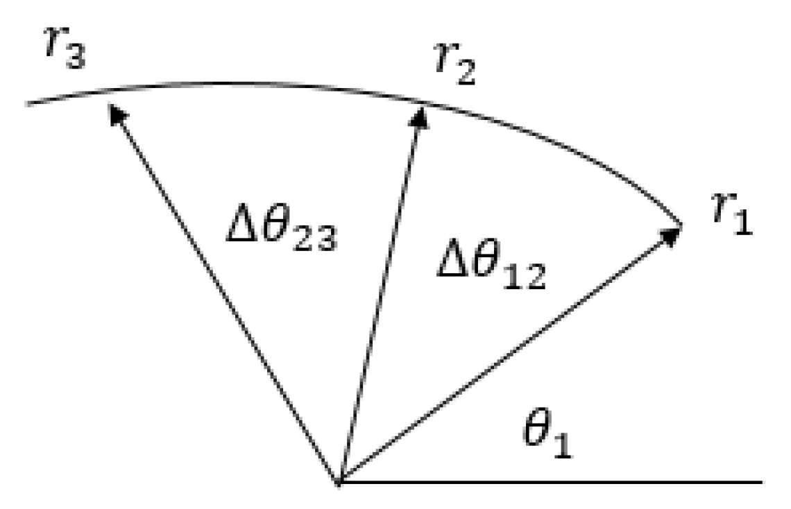
Figure 1. Three position vectors and true anomalies.
Applsci 10 02419 g001
Figure 2. Time history of the orbital energy estimate error.
Applsci 10 02419 g002
Figure 3. Three orbits (ellipse, parabola, and hyperbola) with the same initial and final positions.
Applsci 10 02419 g003
Figure 4. Orbit.
Figure 4. Orbit.
Applsci 10 02419 g004
Table 1. Orbital energy computation algorithm.
s e t E n e r g y C o m p u t e ( r 1 , r 2 , r 3 )
1 r 1 = r 1 r 1 , r 2 = r 2 r 2 , r 3 = r 3 r 3
2 Δ θ 12 = c o s 1 r 1 r 2 r 1 r 2 , Δ θ 13 = c o s 1 r 1 r 3 r 1 r 3 , Δ θ 23 = Δ θ 13 Δ θ 12
3 p = s i n Δ θ 13 s i n Δ θ 12 s i n Δ θ 23 ( s i n Δ θ 13 r 2 s i n Δ θ 12 r 3 s i n Δ θ 23 r 1 )
4 e   s i n θ 1 = 1 + ( p r 1 1 ) c o s Δ θ 12 p r 2 s i n Δ θ 12
5 e   c o s θ 1 = p r 1 1
6 θ 1 = tan 1 ( e s i n θ 1 e c o s θ 1 )
7 e = p r 1 1 c o s θ 1
8 s e t = μ ( 1 e 2 ) 2 p