Article

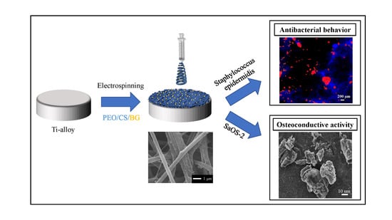
Antibacterial and Osteoconductive Effects of Chitosan/Polyethylene Oxide (PEO)/Bioactive Glass Nanofibers for Orthopedic Applications

1
Faculty of Materials Science and Engineering, Ceramic Physics Laboratory, Kyoto Institute of Technology, Sakyo-ku, Matsugasaki, Kyoto 606-8585, Japan
2
Department of Immunology, Graduate school of Medical Science, Kyoto Prefectural University of Medicine, Kamigyo-ku, Kyoto 602-8566, Japan
3
Faculty of Materials Science and Engineering, Kyoto Institute of Technology, Matsugasaki, Sakyo, Kyoto 606-8585, Japan
4
Department of Dental Medicine, Graduate School of Medical Science, Kyoto Prefectural University of Medicine, Kamigyo-ku, Kyoto 602-8566, Japan
5
Department of Orthopedic Surgery, Tokyo Medical University, 6-7-1 Nishi-Shinjuku, Shinjuku-ku, Tokyo 160-0023, Japan
6
The Center for Advanced Medical Engineering and Informatics, Osaka University, 2-2 Yamadaoka, Suita, Osaka 565-0871, Japan
*
Author to whom correspondence should be addressed.
Appl. Sci. 2020, 10(7), 2360; https://doi.org/10.3390/app10072360
Submission received: 3 March 2020 / Revised: 21 March 2020 / Accepted: 23 March 2020 / Published: 30 March 2020
(This article belongs to the Special Issue Permanent and Long-Term Biodegradable Biomaterials)

Abstract

:
This study investigated the efficiency of chitosan/polyethylene oxide (PEO)-based nanofibers with incorporated bioactive glass particles as a coating for titanium alloy, in order to improve the bacteriostatic behavior and, concurrently, promote the production of mineralized tissue. Nanofibers with and without bioglass powder were fabricated by electrospinning technique and characterized using several microscopic and spectroscopic techniques in order to study their morphological and physiochemical properties. Subsequently, the substrates were tested in vitro against Staphylococcus epidermidis and SaOS-2 human osteosarcoma cell line. After in vitro testing, viability and CFU counting assays combined with fluorescence microscopy showed a clear decrease in bacterial growth on all substrates with increasing time. However, this trend was stronger for substrates coated with nanofibers. Formation of mineralized matrix upon exposure to osteoblasts was confirmed by means of SEM/EDX and the content/distribution of osteocalcin and osteopontin estimated by fluorescence microscopy. Incorporation of bioglass promoted biomineralization and stimulated osteoblasts to produce a higher amount of bone extracellular matrix. The present results suggest that a chitosan/PEO/bioactive glass nanofiber composite applied as coating on titanium alloys could concurrently improve antibacterial and osteoconductive properties and could be a potential candidate for dental and orthopedic applications.

Graphical Abstract

1. Introduction

In the orthopedic and orthodontic fields, titanium alloys are commonly employed for their exceptional combination of biocompatibility, chemical stability, mechanical strength, fatigue resistance and high corrosion resistance [1,2]. However, these materials present some disadvantages that need to be addressed. One of these regards the bacterial-associated diseases/infections during surgery, which could not only lead to implant failure, but also have deleterious side effects. In order to reduce the risk of infection, many preventative strategies have been proposed with the aim of improving the antibacterial ability of the material before surgery [3,4]. Most of the solutions suggested for obtaining an antibacterial surface without losing its bioactivity were based on the use of coatings. One processing technique developed and used nowadays to produce coatings is electrospinning. The type of polymer employed is an important factor responsible for the features of the nanofibers [5]. One of the most used materials for the development of electrospinning nanofibers is chitosan (CS), a biopolymer obtained by deacetylation of chitin, which consists of repeating units of N-acetyl-D-glucosamine and N-glucosamine linked by glycosidic bonds [6]. It possesses various technological properties like biodegradability and biocompatibility, as well as antiviral, insecticidal and antimicrobial activity [7]. CS nanofibers, in particular, were found to be effective in inhibiting the growth of several bacterial strains [8,9,10,11]. Furthermore, due to its structural similarity with glycosaminoglycan (which is one of the main bone and cartilage constituents), it plays important roles in the attachment, differentiation, and morphogenesis of osteoblast cells, providing the cell signals necessary for bone formation [12,13,14]. CS is used in the production of different hybrid scaffolds upon mixing with a second polymer. An example is represented by polyethylene oxide (PEO), a synthetic polymer as a second component in order to improve spinning stability and increase the chain entanglement of chitosan, while the electrical conductivity of the spinning solution decreases [15,16,17,18]. This mixture facilitates fiber formations.
Through electrospinning technique, it is possible to incorporate a variety of bioactive inorganic materials into the polymeric fibers. Among these there are bioactive glasses (BGs), which are commonly used as promising scaffold materials for bone and soft tissue regeneration [19]. For orthopedic applications, different composite nanofiber scaffolds have been developed using CS and other polymers and incorporating bioactive glasses [20,21,22,23,24]. However, in literature no comparison of these composite coatings with uncoated titanium alloys has been yet provided in order to evaluate effectively the antibacterial effect and the simultaneous osteoconductive activity. In this study, the major objective was to produce composite nanofibers deposited on titanium alloy disks using CS blended with polyethylene oxide (PEO) and BG incorporated into the solution in order to improve the bioactivity and the antimicrobial properties of the bulk. The bacteriostatic behavior and the bone tissue formation were monitored in comparison with Ti-alloy and CS/PEO nanofibers without BG, investigating the properties of the different substrates and subsequently performing different biological tests.

2. Experimental Procedures

2.1. Materials

Polished titanium Grade 5 alloy (Ti–6Al–4V ELI) discs (Ti-alloy, henceforth) (distributed by Vincent Metals, Minneapolis, Minnesota) were used as substrates for this work. The composite fibers were produced using Polyethylene oxide (PEO) powder (Mw ~ 2,000,000 Da, Fujifilm Wako Co., Osaka, Japan), low-molecular weight chitosan (CS) powder (Mw ∼ 100,000 Da, SE Chemical Ltd., Kyoto, Japan), Standard 45S5 Bioglass® (BG) powder (Mo-Sci Corporation, Rolla, MO, USA), and acetic acid (99.9% pure, Fujifilm Wako Pure Chemical Industries, Ltd.). Crosslinking was obtained using Glutaraldehyde (GA) (25% in water) (NACALAI TESQUE, Inc., Kyoto, Japan).

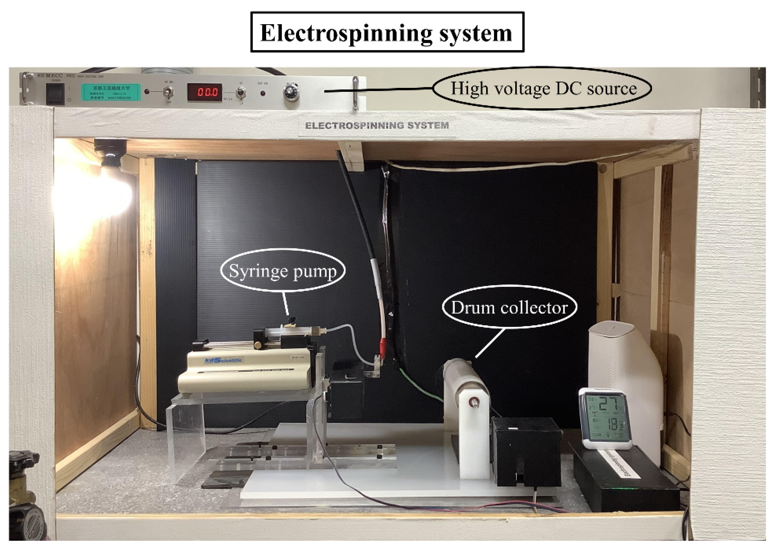
2.2. Sample Preparation by Electrospinning

A CS solution with a concentration of 7 wt% was prepared by dissolving chitosan powder in a mixture of solvents of acetic acid and water (7:3 w/w). The mixture was mixed for two hours using a planetary centrifugal mixer (ARE-310, Thinky Co., Tokyo, Japan). The prepared solution was further mixed by a magnetic stirrer for two days at room temperature to obtain a homogeneous solution. At this point the solution was divided in two classes, one with BG (15 wt% of CS) and one without. Then the PEO powder was added to the obtained solutions with the CS (PEO weight ratio of 2/8). The concentration of chitosan, bioglass and PEO were decided following previous studies presented in literature [25,26,27]. The mixtures were further mixed for 1 h using a planetary centrifugal mixer. The viscosity of each solution was measured by a vibronic viscometer (SV-100A, A&D Co., Japan) at 25 °C; each solution was examined three times (Table 1). The PEO/CS/BG solutions presented a higher value (1.70 ± 0.05 Pa) than the solution without BG (1.05 ± 0.01 Pa).
The fibrous coating layer was prepared using an electrospinning system of our own design (Figure 1).
During the electrospinning process, the feed rate of the solution was kept at 0.1 mL h−1 by a syringe pump (KDS-100, KD Scientific Inc., Holliston, MA, USA). A voltage of 27 kV, generated from a high voltage power supply (HVU-30P100, MECC Co., Japan), was applied to the 30 G needle. The distance between the needle and the collector was fixed at 10 cm. A rotating drum covered by an aluminum foil was used as a collector with a constant rolling rate of 120 rpm. The relative humidity and temperature were monitored by a hygrothermograph placed inside the electrospinning chamber and maintained at the values of 55 ± 5% and 24 ± 2 °C, respectively. Circle-shaped Ti-alloy substrates with a diameter of 12.7 mm were fixed on the stainless steel drum covered by an aluminum foil as a collector. Before the coating procedure, the substrates were washed, sonicated in ethanol/acetone (1:1 w/w) for 30 min and left for drying at 50 °C in the oven. After the coating procedure, all the samples were dried under vacuum for 12 h at 50 °C to completely remove any retained solvents. The samples were placed in a vapor chamber containing 20 ml of GA and were allowed to crosslink the fibers for 24 h. After the crosslinking process, the samples were dried under vacuum for 12 h at 50 °C to remove any remained GA.

2.3. Pre-Test Characterization

In order to verify the wettability of the fibers, the contact angle measurements were conducted using a Phoenix 300 contact-angle system (Kromtek Co., Selangor, Malaysia) at 20 °C. The droplets were further measured using Image software (Rasband, W.S., ImageJ, National Institutes of Health, Bethesda, MD, USA). Briefly, five microliters of deionized water were dropped onto the surface of the substrates, respectively. The average water contact angle value was obtained by measuring at least three different locations across the same sample surface.
FTIR analysis was performed via Attenuated Total Reflection Fourier Transform Infrared spectroscopy (ATR-FTIR, FTIR-4700 with ATR PRO ONE equipped with a diamond prism, Jasco Co., Tokyo, Japan) and samples were scanned between 400 and 2000 cm−1 with a resolution of 4 cm−1 and 100 scans. All results were based on six replicates collected in different areas for each sample. The spectral acquisition and pre-processing of raw data, which included baseline subtraction, smoothing, normalization and fitting, were carried out and interpreted using commercially available software (Origin 8.5, OriginLab Co., Northampton, MA, USA, and LabSpec, Horiba/Jobin-Yvon, Kyoto, Japan).
Surface morphology was characterized at micrometric level with a confocal scanning laser microscope (Laser Microscope 3D and Profile measurements, Keyence, VKx200 Series, Osaka, Japan) capable of high-resolution optical images with depth selectivity. Assembled maps of each sample were collected at 10X and 150X magnifications with numerical apertures between 0.30 and 0.95. The instrument was equipped with an automated x-y stage and autofocus function for the z-range. In order to calculate average roughness (Ra) and mean roughness depth (Rz) values, 25 images randomly acquired from each map surface were used.
Scanning Electron Microscopy (SEM) and Energy Dispersive X-ray Spectroscopy (EDX) (SM-700 1F, JEOL, Tokyo, Japan) were used to acquire high-resolution images and chemical composition maps fibers treated with BG. The substrates were collected on the SEM sample base and then sputter-coated with a layer of platinum before being measured with FE-SEM at an accelerating voltage of 15 kV using different magnifications. The diameters of the fibers were obtained from five SEM images for 200 fibers using image processing software (ImageJ). Data collected using EDX have been performed at 5000X magnification and accelerating voltage of 15 kV.

2.4. Bacterial Culture and Characterization

Freeze-dried pellets of Gram-positive Staphylococcus epidermidis (ATCCTM 14990® purchased from American Type Culture Collection (ATCC)) (S. epidermidis, henceforth) were hydrated in heart infusion (HI) broth (Nissui, Tokyo, Japan) and incubated at 37 °C for 18 h in brain heart infusion (BHI) agar (Nissui). The mixture was subsequently assayed for colony forming units (CFUs) and diluted to a concentration of 1 × 10⁸ CFU mL-1 using phosphate-buffered saline (PBS) in physiological pH and ionic strength. The bacterial suspension was then transferred in 100 μL aliquots onto Petri dishes containing the substrate samples embedded in BHI medium and incubated at 37 °C under aerobic conditions for 12, 24 and 48 h. Following, cell viability was evaluated by a tetrazolium-based assay using the Microbial Viability Assay Kit (WST-8, Dojindo). Substrates were collected and soaked in 1000 μL of PBS in 12-well plates. WST-8 solution was added to each well and OD values measured (the absorbance at 490 nm) using plate reader EMax (molecular devices, San Jose, CA, USA) after incubation for 30–60 min.
The bacterial fluid recovered from the biofilm was diluted with 10-fold serial dilution from 10−1 to 10−5 by PBS, followed by 100 μL of each dilution spread on a chocolate blood agar (CBA) plate. After 4 days of anaerobic culture at 37 °C, the colony number of the plate at an appropriate dilution was counted. The CFU/ml was calculated using the formula: CFU/ml = (no. of colonies x dilution factor) x 10.
At each time point, the test and control samples were observed by fluorescence microscopy (BZ-X700, Keyence, Osaka, Japan). For visualization, bacteria were stained with two different solutions: (i) 4′,6-diamidino-2-phenylindole (DAPI), which binds to and stains DNA blue, thereby imaging the nucleus location; (ii) 5(6)-carboxyfluorescein diacetate (CFDA, Dojindo, Kumamoto, Japan); and, (iii) propidium iodide (PI, Dojindo, Kumamoto, Japan). PI’s red color highlighted dead or injured bacteria. Conversely, CFDA’s green color revealed living bacteria. The staining protocol consisted of adding 1 μL of DAPI, the PI solution, and 15 μL of CFDA solution to the samples, and then incubating them for 5 min at 37 °C. After removing the buffer, the cells were analyzed under the fluorescence microscope.

2.5. Osteoblast-Like Cells Culture and Characterization

SaOS-2 human osteosarcoma cells were first cultured and incubated in 4.5 g/L glucose DMEM (D-glucose, L-Glutamine, Phenol Red, and Sodium Pyruvate) supplemented with 10% fetal bovine serum. They were allowed to proliferate within Petri dishes for 24 h at 37 °C. The final SaOS-2 concentration was 5 × 10⁵ cell/ml. The cultured cells were then deposited on the top surface of the substrates previously sterilized by exposure to UV light. In the osteoconductivity tests, cell seeding took place in an osteogenic medium, which consisted of DMEM supplemented with 50 μg/mL ascorbic acid, 10 mM β-glycerol phosphate, 100 mM hydrocortisone, and 10% fetal bovine calf serum. The samples were incubated up to 7 days at 37 °C. The medium was changed twice during the incubation period.
After exposure to osteoblasts, each batch of different samples was observed using a fluorescence microscope (BZ-X700, Keyence, Osaka, Japan). Prior to examination, the sample surfaces were treated with different immunostaining reagents, including Hoechst 33342 (Dojindo, Kumamoto, Japan), anti-Human Osteocalcin (Takara Bio, Shiga, Japan) (Clone 5-12H, Isotype IgG2b) and anti-Human Osteopontin Rabbit polyclonal antibody (IBL, Gunma, Japan). Hoechst 33342, a cell nucleus stain, served to visualize cell proliferation, while the other two antibodies were used to stain matrix proteins osteocalcin and osteopontin, respectively, whose concentration quantifies the process of mineralization and bone matrix formation. Subsequently, a secondary antibody, Goat anti-Mouse IgG1 Antibody FITC Conjugated (Bethly Laboratories) and Goat anti-Rabbit Antibody PE Conjugated (Bethly Laboratories) were added to enhance signal detection and visualization. In addition, the cell mineralization pattern on the substrates was qualitatively assessed by SEM/EDX.
The scaffolds were dehydrated by using an ethanol–water solution and kept in a fume hood to dry at room temperature. After the scaffolds were dried, they were sputter-coated with platinum and observed.

2.6. Statistical Analysis

The experimental data were analyzed with respect to their statistical meaning by computing their mean value ± one standard deviation and using one-way ANOVA for pre-test characterization tests (morphology and contact angle) and two-way ANOVA with Tukey’s post hoc analysis for biological assays (Microbial Viability assay and CFU counting); p < 0.05 was considered statistically significant and labeled with an asterisk.

3. Results

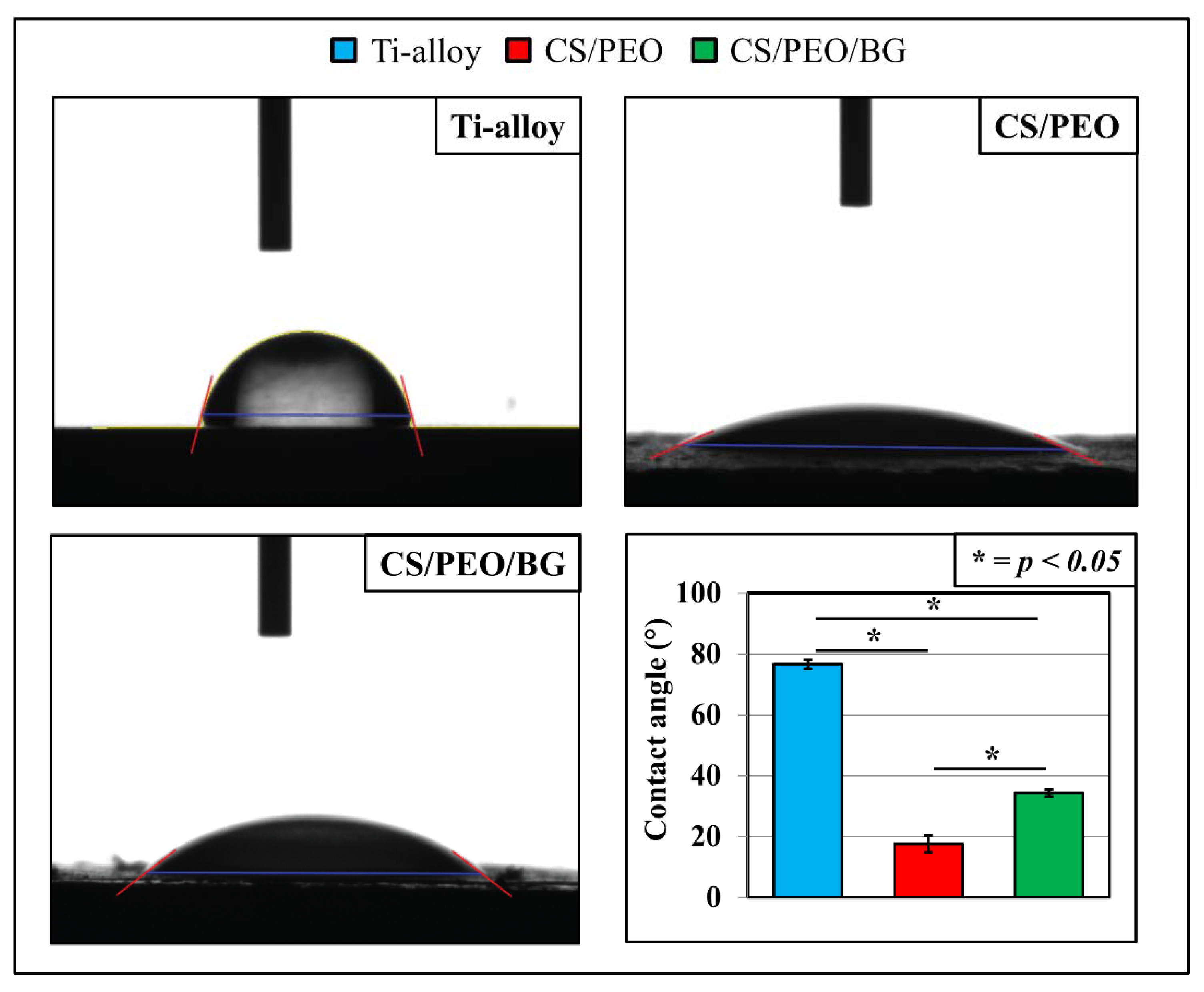
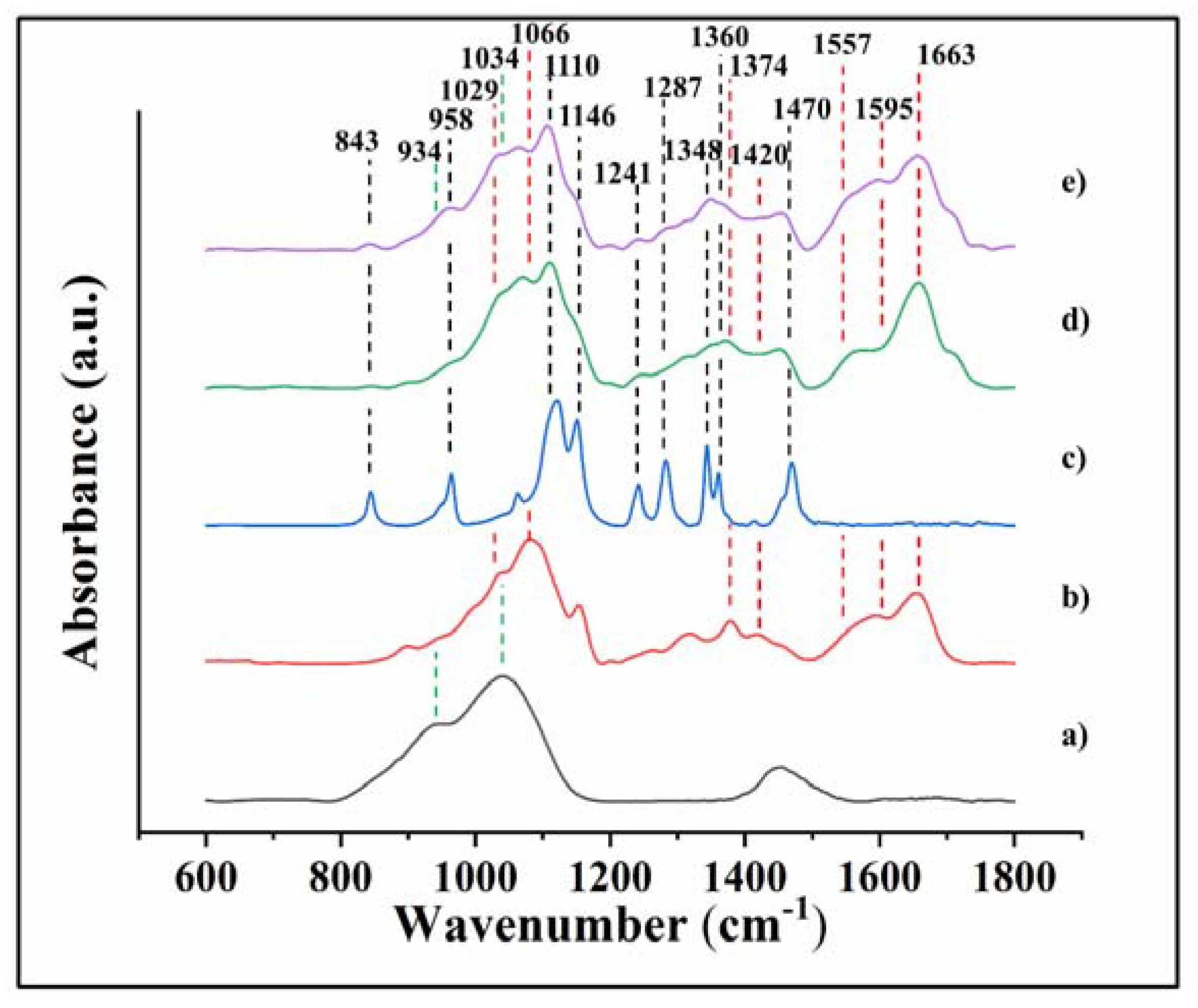
3.1. Pre-Test Characterization

Figure 2 shows representative images of water contact angles as measured on the three samples. The uncoated Ti-alloy substrate was the least hydrophilic and presented a contact angle of 71° ± 1°. The two samples coated with fibers achieved a remarkable improvement in hydrophilicity, in particular the CS/PEO with a contact angle of 18° ± 3°, while the one functionalized with BG had a contact angle of 34° ± 1°.
In order to fully characterize the starting materials, dominant peaks of FTIR spectra of BG, CS, PEO, CS/PEO, and CS/PEO/BG (a–e) were identified as shown in Figure 3.
The spectrum of PEO presented main bands of asymmetric and symmetric stretching of C=O at 1110 and 1146 cm−1, respectively [28,29]; and bands related to CH2 asymmetric stretching (1287 cm−1), CH2 symmetric twisting (1241 cm−1) and two bands related to CH2 wagging (1348 and 1360 cm−1), respectively [28,30,31,32]. About CS, two main ranges between 1000 and 1200 cm−1 and between 1500 and 1700 cm−1 are characteristic of the compounds. In the first range, mainly, there are bands of C-O stretching (1029 cm−1) and symmetric and asymmetric stretching of C-O (1066 cm−1), while the second range is characterized by vibrational modes of amide II (N-H bending at 1557 cm−1), amide I (stretching C=O and N-H bending at 1663 and 1595 cm−1, respectively) [28,30,33,34,35]. About the spectrum of BG, three distinct and very broad bands can be identified at 934 cm−1 (Si-O stretching), 1035 cm−1 (Si-O-Si bending) and 1463 cm−1 (carbonate species) [36,37].
The two spectra related to nanofiber-coated surfaces, with and without BG, were analyzed and fitted as reported in Figure 4 and a summary of all the main bands with the indications of the assignment is provided in Table 1 [28,29,30,31,32,33,34,35,36,38,39,40]. Bands indicated previously and referred to PEO and CS compounds are labeled. The spectrum of CS/PEO/BG, in particular, presents Band 3, located at 934 cm−1 and assigned to Si-O stretching, and shows an increase in Band 6 (1029 cm−1), which derives from the contribution of BG (band related to stretching Si-O-Si located at 1035 cm−1). Another important difference is the increase of Band 20 (from 1562 cm−1) (N-H bending of amide II) observed in the CS/PEO/BG spectrum. Analog behavior was detected for Band 21 (1595 cm−1) (N-H bending). Another important feature appearing in both spectra is a preponderant peak located at 1634 cm−1, which corresponds to the imine bond C=N of the Schiff’s base structure, which occurred during crosslinking between amino groups of chitosan and aldehyde groups of glutaraldehyde.
Laser micrographs of the three tested surfaces are shown in Figure 5a–c as obtained at two different magnifications. Images collected at 10X revealed the how the fiber coatings are distributed on all the Ti-alloy surfaces. Some raised clusters are clearly visible and related to the drying of polymer droplets on the tip of the needle during the electrospinning. These areas influenced the Rz parameters for each of the types of substrates coated by electrospinning. Analyzing the topology of the Ti-alloy, the surface appeared affected by long grooves with a depth in the micrometer order clearly visible at both magnifications. Average roughness value, Ra, and mean Roughness depth, Rz, were obtained by laser profilometry and their differences statistically validated.
The graphs reported in Figure 6 display the same trend. The Ti-alloy uncoated showed statistically relevant differences (p < 0.05) with both of the other two fiber-coated substrates possessing the lowest average roughness and mean roughness depth, 0.23 ± 0.01 μm and 3.73 ± 0.41 μm, respectively. About CS/PEO (Ra 0.85 ± 0.18 μm and Rz 17.48 ± 4.26 μm) and CS/PEO/BG (Ra 0.84 ± 0.17 μm and Rz 16.01 ± 1.69 μm), no statistical differences were identified between each other.
The fiber distribution and size was measured by using SEM (Figure 7). CS/PEO fibers (Figure 7a) were smooth and randomly oriented with a narrow distribution of diameters (Figure 7b), 294 ± 64 nm. The average fiber diameter for CS/PEO/BG was bigger (493.21 ± 77.11 nm) (Figure 7d) and some groups presented the same orientations adhering together (Figure 7c). Another important feature regards the formation of nanowebs within the nanofibers, clearly visible especially in the CS/PEO, with a diameter varying from 50 to 90 nm. These ultrathin nanowire formations are attributed to the phase separation of charged droplets generated during electrospinning under high electric forces, including electrostatic force, drag force, and gravity.
EDX mapping, collected at 5000X magnification, permitted to reveal the distribution of different elements, in particular carbon (red color), as the major components of fibers and silicon and calcium (green and blue, respectively), indicating the BG particles in the fibers (Figure 8). The CS/PEO (Figure 8a) shows clearly the absence of both silicon and calcium, while in the CS/PEO/BG (Figure 8b) they are clearly observable, especially silicon as the major component of BG particles, which showed large bright green spots compared with calcium represented by small spots deposited on the fibers.

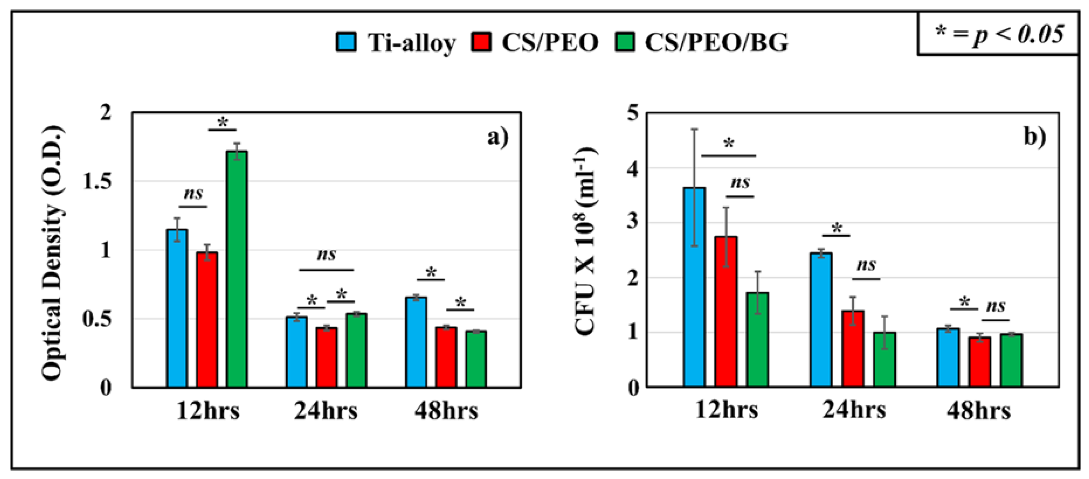
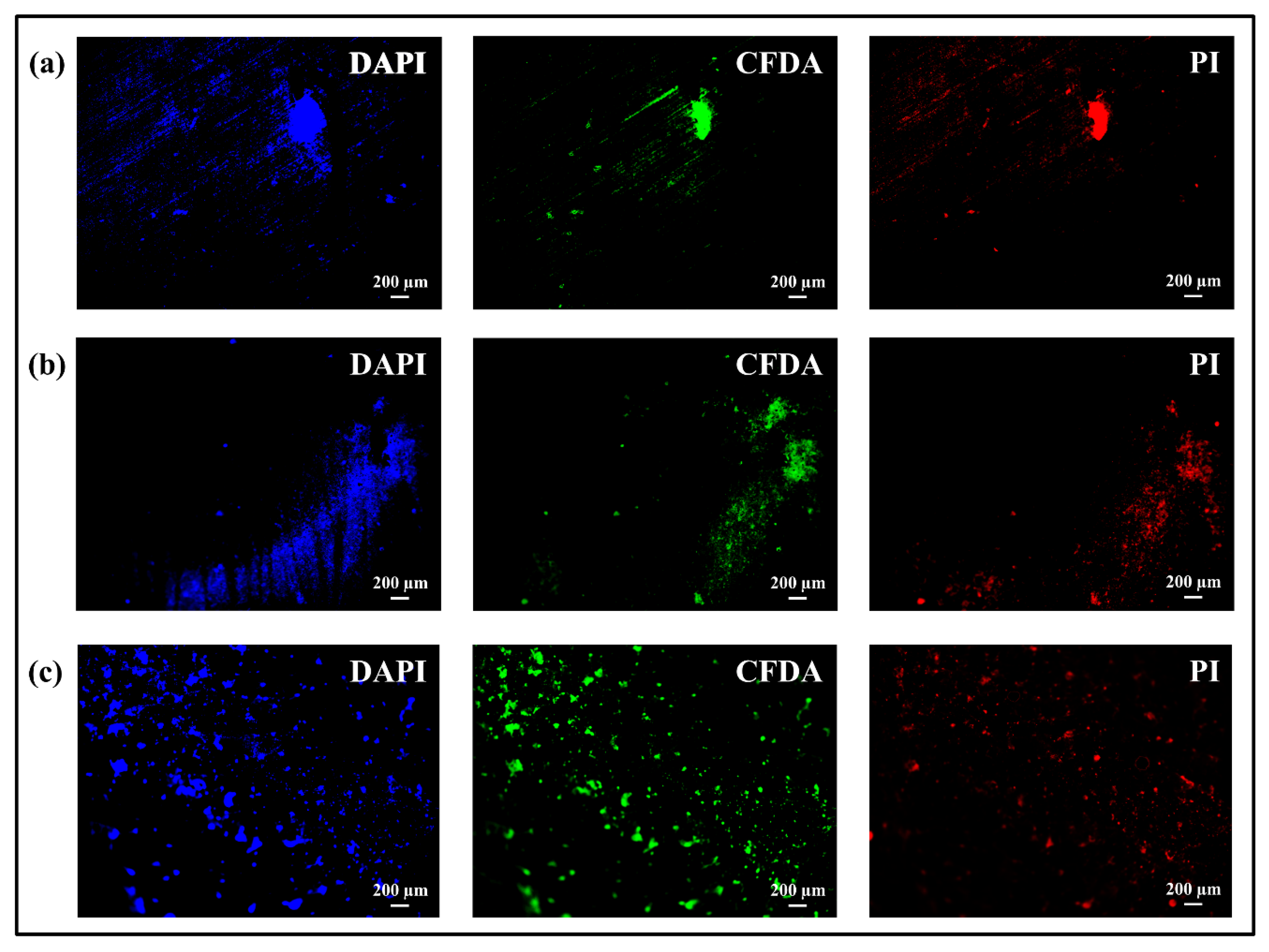
3.2. Bacterial Tests: Microbial Viability Assay, CFU Counting and Fluorescence Microscope

As shown in Figure 9a,b, bacterial cell viability and CFU counting was performed at three different times, 12, 24 and 48 h, respectively. About the Microbial viability assay (Figure 9a), at 12 h CS/PEO/BG showed the highest OD value (1.72 ± 0.06), indicating the largest living bacteria number among the samples. Ti-alloy and CS/PEO had lower OD values (1.15 ± 0.08 and 0.98 ± 0.06) and did not present any significant difference between each other (p < 0.05). A general decrease of OD value occurred for all the samples analyzed at 24 h. The bacterial growth trend of CS/PEO presented the lowest OD value (0.43 ± 0.02), as compared to OD values for Ti-alloy (0.51 ± 0.03) and CS/PEO/BG (0.53 ± 0.01), which were not significantly different (p < 0.05). At 48 h of exposure, CS/PEO/BG had the lowest OD value (0.41 ± 0.01), while Ti-alloy presented a slight increase and the highest OD value (0.65 ± 0.02), whereas CS/PEO (0.44 ± 0.02) had an intermediate OD value. At this time of exposure, OD values between the tested samples were significantly different (p < 0.05).
Figure 9b displays the antibacterial activity performed by fiber-coated substrates evaluated by a time-lapse CFU counting assay obtained after culturing the bacteria collected from the surface. Results indicated a CFU number decreasing with the time increase on all the substrates treated. At all three times of exposure, uncoated Ti-alloy had the highest OD value compared with the two fiber-coated substrates. These latter did not show significant differences between each other at 12 h and 24 h, but at 48 h CS/PEO showed the lowest amount of CFU/ml compared to CS/PEO/BG (p < 0.05).
Fluorescence micrographs were obtained for all samples after first staining them with PI, CFDA, and DAPI markers, which colored dead bacteria (red), live bacteria (green), and nuclei (blue), respectively. Figure 10 illustrates images collected at 12 h of the different samples after exposure to S. epidermidis (constant magnification of 4X). On CS/PEO/BG a high amount of cells, homogeneously distributed, was detected and most of them corresponded to living cells (cf. DAPI blue-stained and CFDA green-stained micrographs in Figure 10c). Differently, in images of Ti-alloy substrates (Figure 10a), bacteria were located in few spots related to both living and dead cells. Also on CS/PEO, bacteria were not homogeneously distributed and the PI-red stained images in the micrographs indicated how these areas were associated to dead bacteria (Figure 10b).
Images were collected at 48 h for all the samples shown in Figure 11. For Ti-alloy substrate, a relatively high amount of bacteria was detected over the entire sample’s surface (cf. DAPI blue-stained micrographs in Figure 11b). The level of living bacteria was still high, as suggested by the CFDA green-stained areas, but some PI red-stained areas associated with dead bacteria clearly indicated that lysis had occurred. Micrographs of CS/PEO (Figure 11b) presented a relatively low density of bacterial cells. They were located in few areas not homogeneously distributed on the entire surface and containing both dead and living cells. Regarding the CS/PEO/BG substrate, bacterial cell density seemed lower than on Ti-alloy (cf. DAPI blue-stained micrographs in Figure 11c), even if distributed over the entire surface. No huge spots of cells related to colony were present as seen in micrographs collected of the other two samples. The amount of green-stained living bacteria was lower compared with red-stained dead cells (cf. CFDA and PI-stained micrographs in Figure 11c); this indicated a reduction of cell proliferation concurrent with an increase of cell lysis.

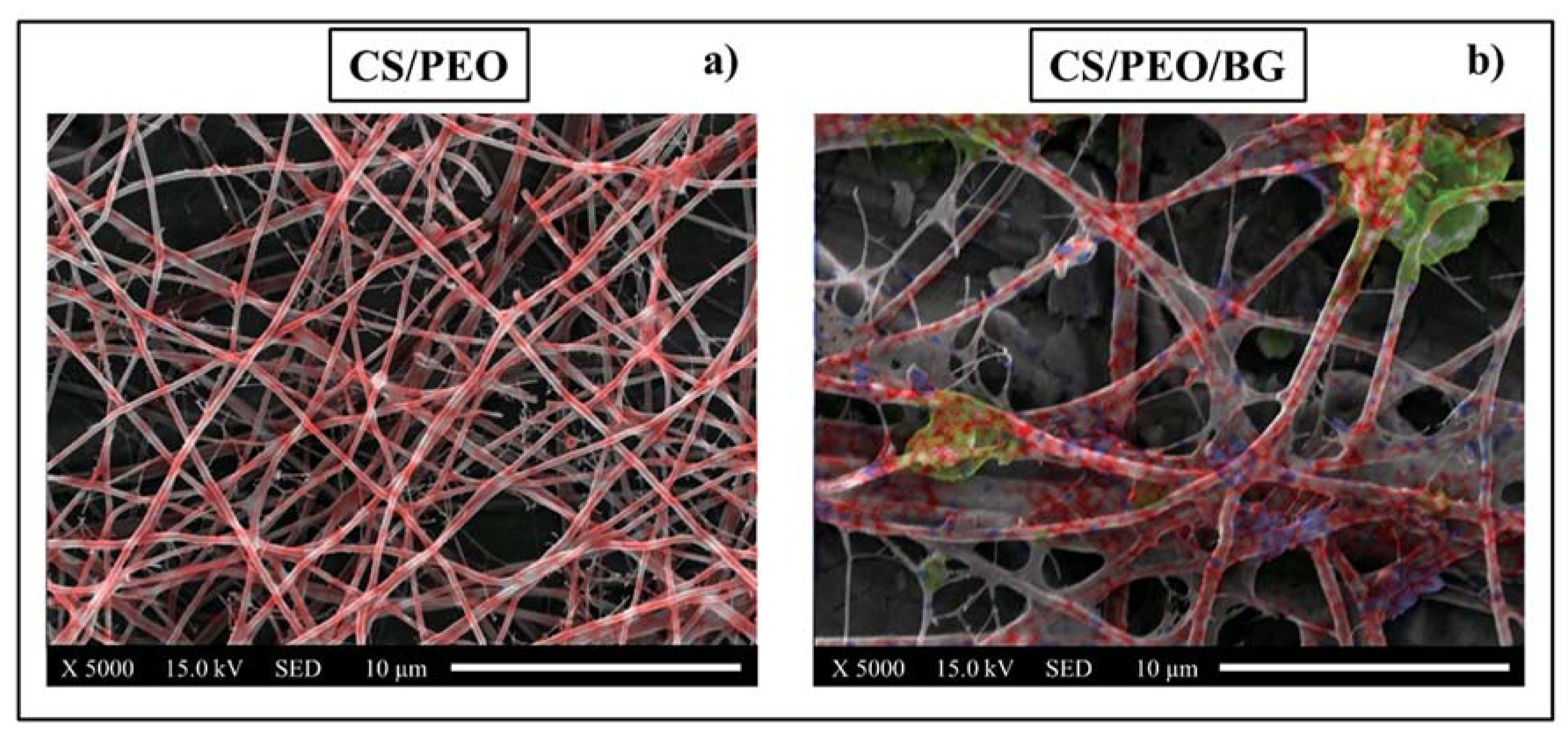
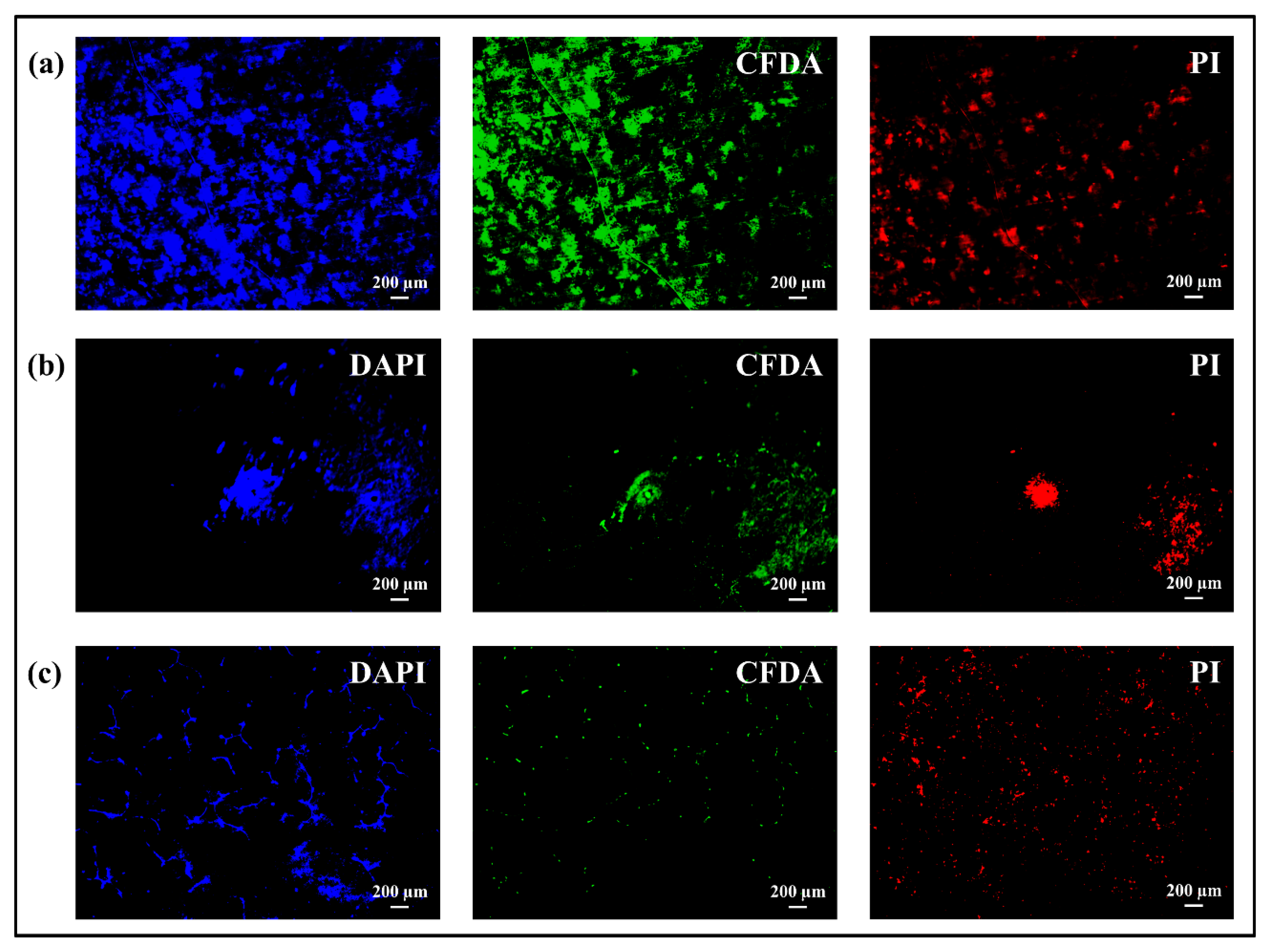
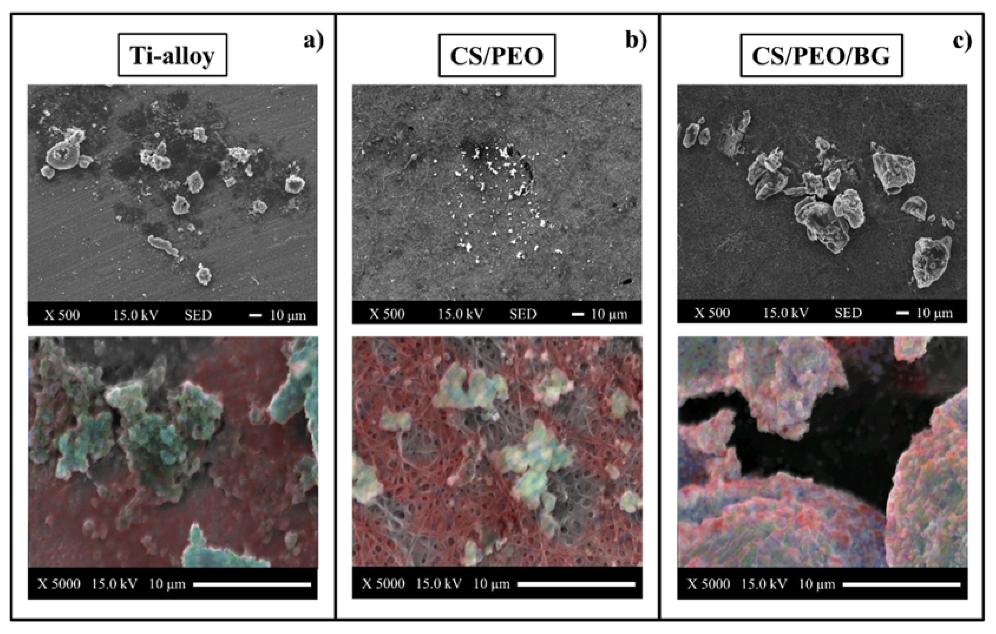
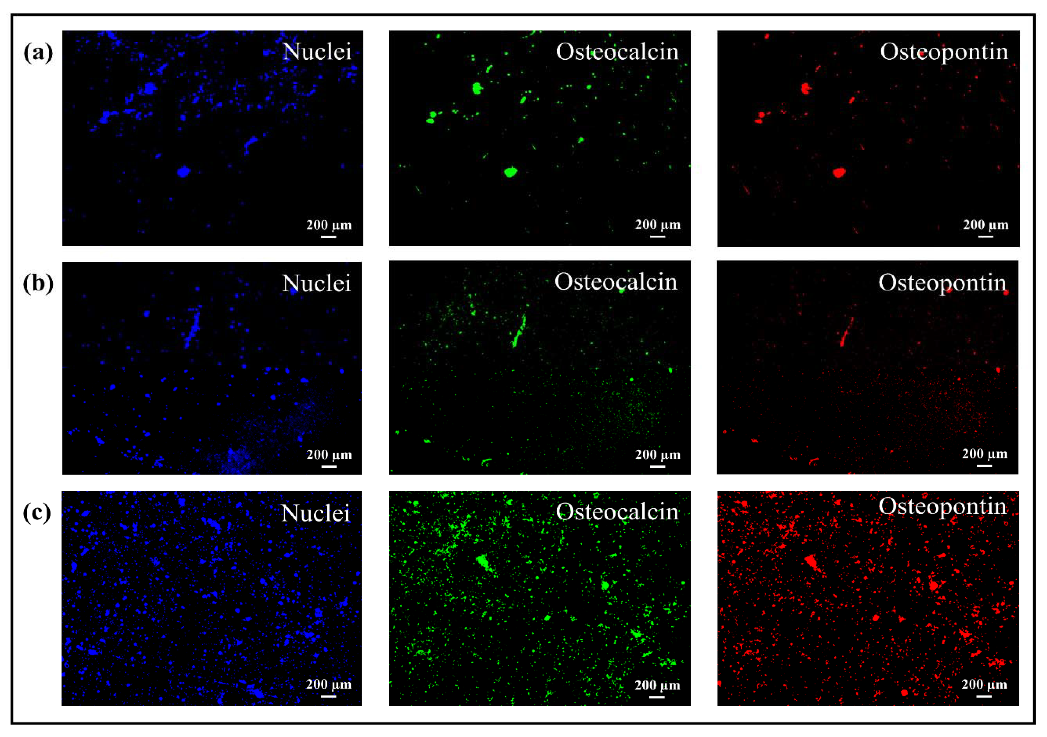
3.3. Osteoconductivity Tests: SEM/EDX and Fluorescence Microscope

Mineralization pattern of SaOS-2 cell-grown apatite on the three samples was provided by SEM/EDX, as shown in Figure 12a–c. SEM images, collected at 500X, showed significant differences among the samples. In particular CS/PEO did not show high-mineralized matrix formation. Few small spots were located randomly on the surface and they were related to calcium (Ca) (blue) and phosphorous (P) (green), indicating the beginning of mineralization as shown by EDX. The carbon (C) signal arises from the fiber substrate and not from the presence of an organic matrix. The Ti-alloy SEM image presented bigger mineralized areas associated to bone formation. This was confirmed by the EDX image where Ca-blue and P-green stained areas of mineral components were surrounded by organic matrix (C-red stained). As with Ti-alloy, the CS/PEO/BG substrate also presented some mineralized nodules having a larger size, compared to the ones in CS/PEO. The EDX image confirmed that these were related to mineral and organic components of mineralized tissue. In particular, red-stained areas associated to the matrix indicated how the mineralization process was progressing faster. An important aspect displayed by SEM images was also that no scratches, holes, or fiber dissolution were involved, indicating how the crosslinking increased stability in the solution.
Figure 13 shows the results of fluorescence microscopy obtained after treatment with different staining in order to verify the presence of osteocalcin and osteopontin, two osteoblast differentiation markers used to detect the bone formation process. CS/PEO/BG images display a homogeneous distribution of cells and related osteocalcin and osteopontin small spots located on the entire surface (Figure 13c) and associated with a mineralized matrix enhancement. Differently, on the fiber-coated sample without BG, a very limited bioactive response to the cells, homogeneously distributed on the substrate, was detected due to weak signals of osteopontin and osteocalcin (Figure 13b).
On Ti-alloy substrates, as illustrated in Figure 13a, some big stained spots of osteocalcin and osteopontin are visible, even if not homogeneously distributed as on the CS/PEO/BG surface. Furthermore, different areas of nuclei seem distributed over most parts of the surface, indicating a cell adhesion promotion.

4. Discussion

The development of a coating for Ti-alloy made of CS/PEO fibers functionalized with BG by electrospinning method was studied by different techniques in order to understand the topography and chemistry of the coatings. The most important aspect that emerged during pre-test characterizations was the variation of the fibers’ physiochemical and morphological properties, correlated with the presence of BG. Before electrospinning, the solution containing BG presented a higher viscosity and this could be correlated with an increase in fiber diameter. Incorporating BG, the presence of rigid particles increased the shear viscosity of dilute suspensions compared to that of neat liquids. These results are consistent with previous reports, which show how an increase in viscosity arises from implementing the polymeric solution for electrospinning with bioactive powders, in turn affecting the fiber size and distributions [41,42]. Consequently, the change in fiber diameter had an effect on wettability. In fact, substrates with CS/PEO/BG had a higher contact angle than samples without bioglass. These data also found confirmation in other works in literature in which changes in voltage led to fibers with different diameters. Analyses of contact angle showed that by increasing the size of the fibers the contact angle also increased [43]. Adding BG into the mixture usually produces a relatively rough and more hydrophilic surface [23], but in our case the use of bioglass did not bring any variation in terms of average roughness or mean roughness depth, despite the presence of small particles related to silicon and calcium as detected by EDX.
The increase in roughness derived from the contribution of fiber distribution did not affect the bacterial adhesion since, as seen through the 12 h Microbial viability test, the optical density value did not change much between the Ti-alloy and the CS/PEO substrates. In the case of CS/PEO/BG, the high degree of optical density related to the number of living bacteria on the surface can be associated to the presence of BG. This is because during the fiber preparation process BG interacted with CS. In particular, in the FTIR spectrum there was an increase in intensity for bands related to NH bending of the amide groups and, especially, the band located at 1560 cm−1 was found to be an index of interactions between BG and chitosan [23,44]. The dissolution of chitosan in dilute acetic acid leads to the protonation of NH2 groups [21,45]. The incorporation of BG initially inhibited the effect of chitosan as visible at 12 h by WST and fluorescence microscope images. With the dissolution of BG over time, the protonated NH3+ of the CS could interact through electrostatic forces with electronegative sites on the surface of the bacterial membrane, promoting changes in membrane wall permeability (osmotic imbalances), inhibiting bacterial growth, leading to leakage of intracellular electrolytes as proteins and other low molecular weight constituents, and binding the cell via protonated amino groups, which in turn led to inhibition of the microbial RNA synthesis [44,46,47,48,49,50,51,52]. In fact, the antibacterial behavior of the chitosan was clearly visible on both coated surfaces at 24 and 48 h compared to Ti-alloy, according to both Microbial viability sssay and CFU counting.
The tests with osteoblasts highlighted some important aspects related to the formation of a mineral and organic matrix on various surface samples. The incorporation of BG into the CS/PEO fibers led to a marked improvement compared to the CS/PEO fibers and Ti-alloy. This represented a further confirmation of how BG acts as a source of ions that can be used by osteoblasts to produce mineral (hydroxyapatite) [53]. When in physiological solution with cells that ion species derive from dissolution of the glass, they produced an increase of pH with the formation of silanol Si-OH groups, which subsequently tend to form a SiO2 layer. This latter attracts Ca2+ and PO43−, forming calcium phosphate clusters into the newly mineralized tissue, and enhances activation of osteogenic biomarkers [39]. The homogeneous distribution of cells on the surface of CS/PEO/BG was another important aspect that emerged compared to the Ti-alloy, capable of stimulating a localized adhesion and production of large clusters of mineralized matrix. Also the CS/PEO substrates presented homogeneous distribution of nuclei on all the surfaces, but the formation of mineralized tissue was at the initial states seen in all the results, indicating how the implementation with BG strongly improved the osteoconductive performance.

5. Conclusions

The development of a new coating on Ti-alloy composed of chitosan, polyethylene oxide and bioglass and made by Electrospinning was tested with osteoblast-like cells (SaOS-2) and Gram-positive S. epidermidis to investigate osteoconductive activity and bacteriostatic behavior. The data obtained through pre- and post-treatment analyses revealed differences between the different substrates, which led to the following conclusions:
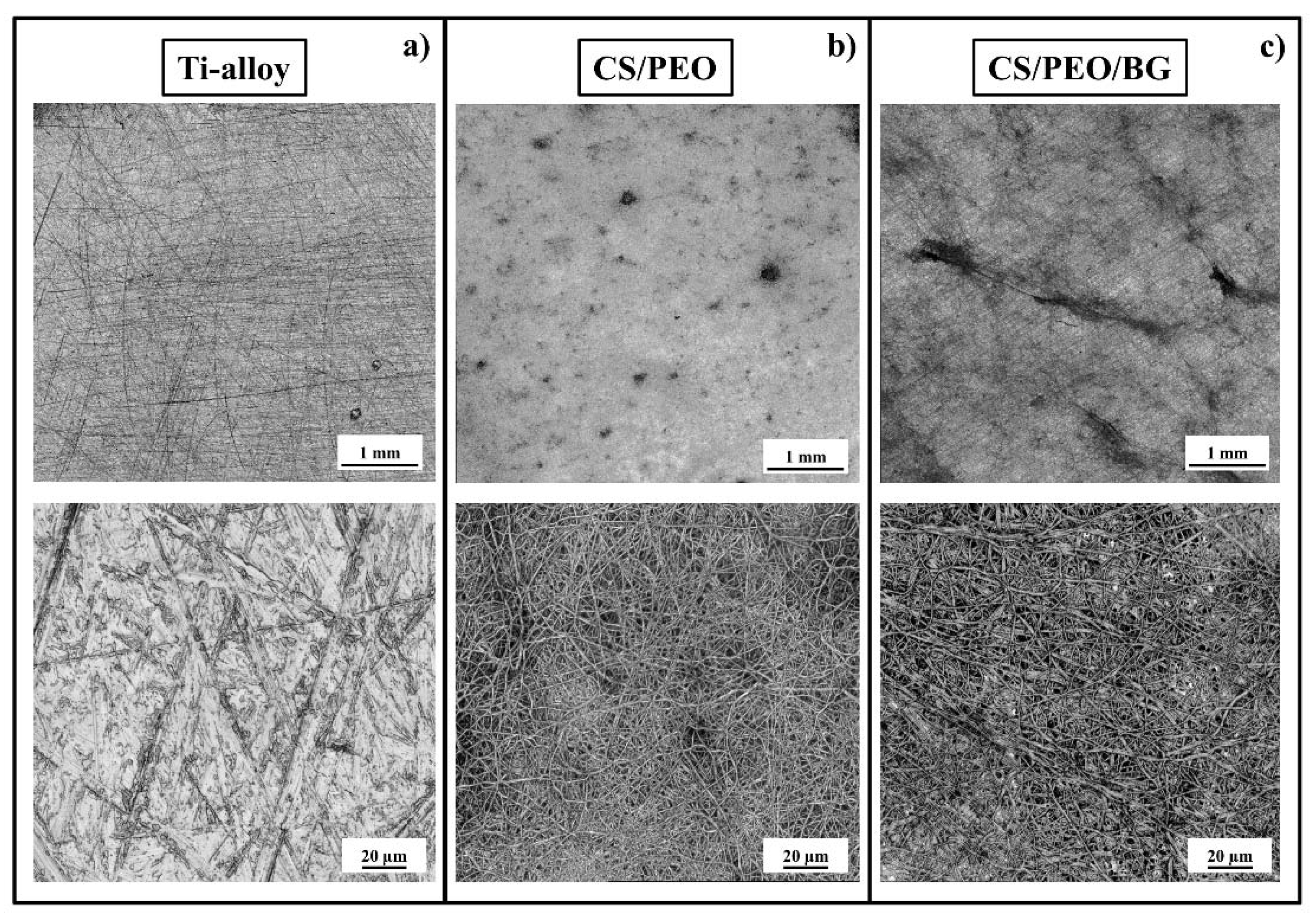
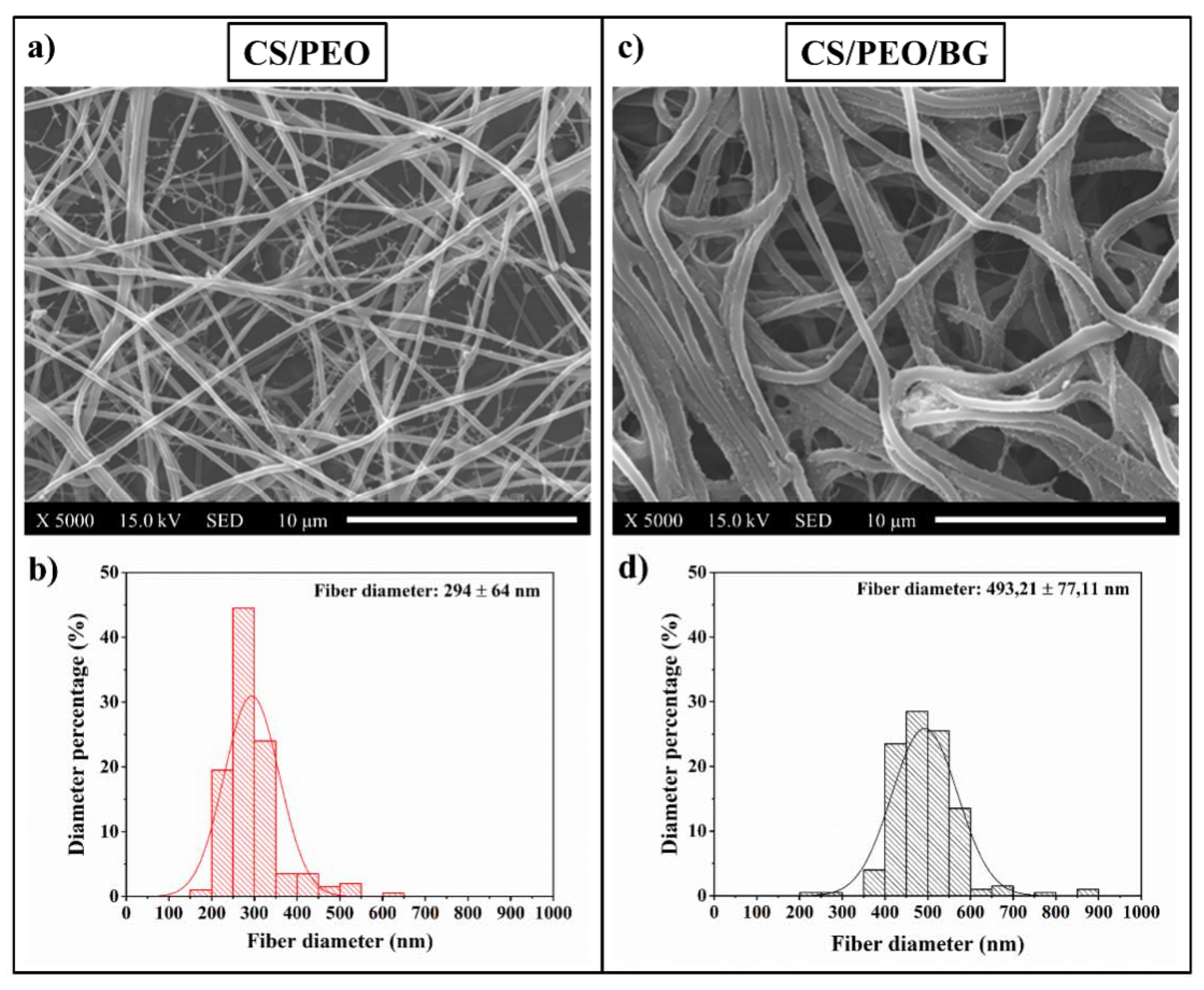
  • By adding bioglass to the polymeric solution, the viscosity increased significantly and this involved changes in the fibers’ morphological and physiochemical properties (diameter of the fibers and wettability);
  • Both coatings showed a more effective action against bacteria over time compared to uncoated Ti-alloy, even if in the case of coating of nanofibers with bioglass there was an initial adhesion and proliferation due to the presence of glass, partly inhibiting the antibacterial effect of chitosan;
  • Cells adhered to all substrates, but the coating incorporated with bioglass provided a better performance regarding the formation of mineralized tissue because some areas related to mineralized organic matrix (osteocalcin and osteopontin) were homogeneously distributed on the entire surface.
In conclusion, applying a composite coating of chitosan fibers, polyethylene oxide and bioglass on Ti-alloy substrates results in the combined action of chitosan and bioglass bringing significant improvements to the surface properties of the substrates, inducing stronger and durable antibacterial resistance and simultaneously implementing the formation of mineralized tissue.

Author Contributions

Conceptualization: F.B. and H.N.D.; methodology: H.N.D., P.P.V.; software: M.Z., P.P.V.; validation: G.P., E.O., and T.A.; formal analysis: F.B., M.Z.; investigation: F.B., H.N.D., P.P.V.; resources: O.M., N.T., W.S.; data curation: F.B., H.N.D.; writing—original draft preparation: F.B.; writing—review and editing: G.P., E.M.; visualization: W.Z.; supervision: G.P., K.K., E.M.; project administration: F.B., E.M. All authors have read and agreed to the published version of the manuscript.

Funding

This research received no external funding.

Conflicts of Interest

The authors declare no conflict of interest.

References

  1. Niinomi, M. Mechanical properties of biomedical titanium alloys. Mater. Sci. Eng. A 1998, 243, 231–236. [Google Scholar] [CrossRef]
  2. Wu, S.; Liu, X.; Yeung, K.W.; Guo, H.; Li, P.; Hu, T.; Chung, C.Y.; Chu, P.K. Surface nano-architectures and their effects on the mechanical properties and corrosion behavior of Ti-based orthopedic implants. Surf. Coat. Technol. 2013, 233, 13–26. [Google Scholar] [CrossRef]
  3. Romanò, C.L.; Scarponi, S.; Gallazzi, E.; Romanò, D.; Drago, L. Antibacterial coating of implants in orthopaedics and trauma: A classification proposal in an evolving panorama. J. Orthop. Surg. Res. 2015, 10, 157. [Google Scholar] [CrossRef] [Green Version]
  4. Kazemzadeh-Narbat, M.; Lai, B.F.; Ding, C.; Kizhakkedathu, J.N.; Hancock, R.E.; Wang, R. Multilayered coating on titanium for controlled release of antimicrobial peptides for the prevention of implant-associated infections. Biomaterials 2013, 34, 5969–5977. [Google Scholar] [CrossRef] [PubMed]
  5. Ji, W.; Sun, Y.; Yang, F.; van den Beucken, J.J.; Fan, M.; Chen, Z.; Jansen, J.A. Bioactive electrospun scaffolds delivering growth factors and genes for tissue engineering applications. Pharm. Res. 2011, 28, 1259–1272. [Google Scholar] [CrossRef] [PubMed] [Green Version]
  6. Galed, G.; Miralles, B.; Paños, I.; Santiago, A.; Heras, Á. N-Deacetylation and depolymerization reactions of chitin/chitosan: Influence of the source of chitin. Carbohydr. Polym. 2005, 62, 316–320. [Google Scholar] [CrossRef]
  7. Rabea, E.I.; Badawy, M.E.T.; Stevens, C.V.; Smagghe, G.; Steurbaut, W. Chitosan as antimicrobial agent: Applications and mode of action. Biomacromolecules 2003, 4, 1457–1465. [Google Scholar] [CrossRef]
  8. Jung, K.H.; Huh, M.W.; Meng, W.; Yuan, J.; Hyun, S.H.; Bae, J.S.; Hudson, S.M.; Kang, I.K. Preparation and antibacterial activity of PET/chitosan nanofibrous mats using an electrospinning technique. J. Appl. Polym. Sci. 2007, 105, 2816–2823. [Google Scholar] [CrossRef]
  9. Spasova, M.; Paneva, D.; Manolova, N.; Radenkov, P.; Rashkov, I. Electrospun chitosan-coated fibers of poly (L-lactide) and poly (L-lactide)/poly (ethylene glycol): Preparation and characterization. Macromol. Biosci. 2008, 8, 153–162. [Google Scholar] [CrossRef]
  10. Son, B.; Yeom, B.Y.; Song, S.H.; Lee, C.S.; Hwang, T.S. Antibacterial electrospun chitosan/poly (vinyl alcohol) nanofibers containing silver nitrate and titanium dioxide. J. Appl. Polym. Sci. 2009, 111, 2892–2899. [Google Scholar] [CrossRef]
  11. Torres-Giner, S.; Ocio, M.J.; Lagaron, J.M. Development of active antimicrobial fiber-based chitosan polysaccharide nanostructures using electrospinning. Eng. Life Sci. 2008, 8, 303–314. [Google Scholar] [CrossRef]
  12. Oudadesse, H.; Bui, X.V.; Le Gal, Y.; Mostafa, A.; Cathelineau, G. Chitosan effects on bioactive glass for application as biocopmosite biomaterial. Int. J. Biol. Biomed. Eng. 2011, 5, 49–56. [Google Scholar]
  13. Zhang, Y.; Venugopal, J.R.; El-Turki, A.; Ramakrishna, S.; Su, B.; Lim, C.T. Electrospun biomimetic nanocomposite nanofibers of hydroxyapatite/chitosan for bone tissue engineering. Biomaterials 2008, 29, 4314–4322. [Google Scholar] [CrossRef]
  14. Xu, J.; Zhang, J.; Gao, W.; Liang, H.; Wang, H.; Li, J. Preparation of chitosan/PLA blend micro/nanofibers by electrospinning. Mater. Lett. 2009, 63, 658–660. [Google Scholar] [CrossRef]
  15. Spasova, M.; Manolova, N.; Paneva, D.; Rashkov, I. Preparation of chitosan-containing nanofibres by electrospinning of chitosan/poly (ethylene oxide) blend solutions. e-Polymers 2004, 4, 1–12. [Google Scholar] [CrossRef]
  16. Pakravan, M.; Heuzey, M.C.; Ajji, A. A fundamental study of chitosan/PEO electrospinning. Polymer 2011, 52, 4813–4824. [Google Scholar] [CrossRef]
  17. Li, L.; Hsieh, Y.L. Chitosan bicomponent nanofibers and nanoporous fibers. Carbohydr. Res. 2006, 341, 374–381. [Google Scholar] [CrossRef]
  18. Duan, B.; Dong, C.; Yuan, X.; Yao, K. Electrospinning of chitosan solutions in acetic acid with poly (ethylene oxide). J. Biomater. Sci. Polym. Ed. 2004, 15, 797–811. [Google Scholar] [CrossRef]
  19. Jones, J.R.; Gentleman, E.; Polak, J. Bioactive glass scaffolds for bone regeneration. Elements 2007, 3, 393–399. [Google Scholar] [CrossRef]
  20. Talebian, S.; Mehrali, M.; Mohan, S.; Balaji raghavendran, H.R.; Mehrali, M.; Khanlou, H.M.; Kamarul, T.; Afifi, A.M.; Abass, A.A. Chitosan (PEO)/bioactive glass hybrid nanofibers for bone tissue engineering. RSC Adv. 2014, 4, 49144–49152. [Google Scholar] [CrossRef]
  21. Liverani, L.; Lacina, J.; Roether, J.A.; Boccardi, E.; Killian, M.S.; Schmuki, P.; Schubert, D.W.; Boccaccini, A.R. Incorporation of bioactive glass nanoparticles in electrospun PCL/chitosan fibers by using benign solvents. Bioact. Mater. 2017, 3, 55–63. [Google Scholar] [CrossRef] [PubMed]
  22. Goh, Y.F.; Akram, M.; Alshemary, A.; Hussain, R. Antibacterial polylactic acid/chitosan nanofibers decorated with bioactive glass. Appl. Surf. Sci. 2016, 387, 1–7. [Google Scholar] [CrossRef]
  23. Aguilar, A.; Zein, N.; Harmouch, E.; Hafdi, B.; Bornert, F.; Offner, D.; Clauss, F.; Fioretti, F.; Hunk, O.; Benkirane-Jessel, N.; et al. Application of chitosan in bone and dental engineering. Molecules 2019, 24, 3009. [Google Scholar] [CrossRef] [PubMed] [Green Version]
  24. Shalumon, K.T.; Sowmya, S.; Sathish, D.; Chennazhi, K.P.; Nair, S.V.; Jayakumar, R. Effect of incorporation of nanoscale bioactive glass and hydroxyapatite in PCL/chitosan nanofibers for bone and periodontal tissue engineering. J. Biomed. Nanotechnol. 2013, 9, 430–440. [Google Scholar] [CrossRef]
  25. Geng, X.; Kwon, O.H.; Jang, J. Electrospinning of chitosan dissolved in concentrated acetic acid solution. Biomaterials 2005, 26, 5427–5432. [Google Scholar] [CrossRef]
  26. Seo, H.; Matsumoto, H.; Hara, S.; Minagawa, M.; Tanioka, A.; Yako, H.; Inoue, K. Preparation of polysaccharide nanofiber fabrics by electrospray deposition: Additive effects of poly (ethylene oxide). Polym. J. 2005, 37, 391–398. [Google Scholar] [CrossRef] [Green Version]
  27. Foroughi, M.R.; Karbasi, S.; Khoroushi, M.; Khademi, A.A. Polyhydroxybutyrate/chitosan/bioglass nanocomposite as a novel electrospun scaffold: Fabrication and characterization. J. Porous Mater 2017, 24, 1447–1460. [Google Scholar] [CrossRef]
  28. Silva, S.M.; Braga, C.R.; Fook, M.V.; Raposo, C.M.; Carvalho, L.H.; Canedo, E.L. Application of infrared spectroscopy to analysis of chitosan/clay nanocomposites. In Infrared Spectroscopy—Materials Science, Engineering and Technology; InTech: Rijeka, Croatia, 2012; pp. 43–62. [Google Scholar]
  29. Wen, S.J.; Richardson, T.J.; Ghantous, D.I.; Striebel, K.A.; Ross, P.N.; Cairns, E.J. FTIR characterization of PEO + LiN(CF3SO2)2 electrolytes. J. Electroanal. Chem. 1996, 408, 113–118. [Google Scholar] [CrossRef]
  30. Fernandes Queiroz, M.; Melo, K.R.T.; Sabry, D.A.; Sassaki, G.L.; Rocha, H.A.O. Does the use of chitosan contribute to oxalate kidney stone formation? Mar. Drugs 2015, 13, 141–158. [Google Scholar] [CrossRef]
  31. Balakumar, S.; Shajan, X.S. Structural and ionic conductivity studies on nanochitosan incorporated polymer electrolytes for rechargeable magnesium batteries. Chem. Sci. Trans. 2012, 1, 311–316. [Google Scholar]
  32. Sim, L.H.; Gan, S.N.; Chan, C.H.; Yahya, R. ATR-FTIR studies on ion interaction of lithium perchlorate in polyacrylate/poly (ethylene oxide) blends. Spectrochim. Acta Part A Mol. Biomol. Spectrosc. 2010, 76, 287–292. [Google Scholar] [CrossRef] [PubMed]
  33. Dahmane, E.M.; Taourirte, M.; Eladlani, N.; Rhazi, M. Extraction and characterization of chitin and chitosan from Parapenaeus longirostris from Moroccan local sources. Int. J. Polym. Anal. Charact. 2014, 19, 342–351. [Google Scholar] [CrossRef]
  34. Kumirska, J.; Czerwicka, M.; Kaczyński, Z.; Bychowska, A.; Brzozowski, K.; Thöming, J.; Stepnowski, P. Application of spectroscopic methods for structural analysis of chitin and chitosan. Mar. Drugs 2010, 8, 1567–1636. [Google Scholar] [CrossRef] [PubMed] [Green Version]
  35. Wang, T.; Turhan, M.; Gunasekaran, S. Selected properties of pH-sensitive, biodegradable chitosan–poly (vinyl alcohol) hydrogel. Polym. Int. 2004, 53, 911–918. [Google Scholar] [CrossRef]
  36. Bui, X.; Oudadesse, H.; Le Gal, Y.; Mostafa, A.; Cathelineau, G. Microspheres of chitosan-bioactive glass for application in orthopedic surgery. In Vitro Experiment, Recent Researches in Modern Medicine; WSEAS: Cambridge, UK, 2011; pp. 359–367. [Google Scholar]
  37. Anilkumar, K.M.; Jinisha, B.; Manoj, M.; Jayalekshmi, S. Poly (ethylene oxide) (PEO)–Poly (vinyl pyrrolidone) (PVP) blend polymer based solid electrolyte membranes for developing solid state magnesium ion cells. Eur. Polym. J. 2017, 89, 249–262. [Google Scholar] [CrossRef]
  38. Theophile, T. Infrared Spectroscopy: Materials Science, Engineering and Technology; InTech: Rijeka, Croatia, 2012. [Google Scholar]
  39. Kim, S.K. Chitin, Chitosan, Oligosaccharides and Their Derivatives: Biological Activities and Applications; CRC Press: Boca Raton, FL, USA, 2010. [Google Scholar]
  40. Ouis, M.A.; Abdelghany, A.M.; ElBatal, H.A. Corrosion mechanism and bioactivity of borate glasses analogue to Hench’s bioglass. Process. Appl. Ceram. 2012, 6, 141–149. [Google Scholar] [CrossRef]
  41. Kouhi, M.; Morshed, M.; Varshosaz, J.; Fathi, M.H. Poly (ε-caprolactone) incorporated bioactive glass nanoparticles and simvastatin nanocomposite nanofibers: Preparation, characterization and in vitro drug release for bone regeneration applications. Chem. Eng. J. 2013, 228, 1057–1065. [Google Scholar] [CrossRef]
  42. Drew, C.; Wang, X.; Samuelson, L.A.; Kumar, J. The effect of viscosity and filler on electrospun fiber morphology. J. Macromol. Sci. Part A 2003, 40, 1415–1422. [Google Scholar] [CrossRef]
  43. Huang, F.L.; Wang, Q.Q.; Wei, Q.F.; Gao, W.D.; Shou, H.Y.; Jiang, S.D. Dynamic wettability and contact angles of poly (vinylidene fluoride) nanofiber membranes grafted with acrylic acid. Express Polym. Lett. 2010, 4, 551–558. [Google Scholar] [CrossRef]
  44. Chen, C.S.; Liau, W.Y.; Tsai, G.J. Antibacterial effects of N-sulfonated and N-sulfobenzoyl chitosan and application to oyster preservation. J. Food Prot. 1998, 61, 1124–1128. [Google Scholar] [CrossRef]
  45. Rinaudo, M.; Pavlov, G.; Desbrieres, J. Influence of acetic acid concentration on the solubilization of chitosan. Polymer 1999, 40, 7029–7032. [Google Scholar] [CrossRef]
  46. Tsai, G.J.; Su, W.H. Antibacterial activity of shrimp chitosan against Escherichia coli. J. Food Prot. 1999, 62, 239–243. [Google Scholar] [CrossRef] [PubMed]
  47. Hadwiger, L.A.; Kendra, D.G.; Fristensky, B.W.; Wagoner, W. Chitosan both activated genes in plants and inhibits RNA synthesis in fungi. In Chitin in Nature and Technology; Muzzarelli, R.A.A., Jeuniaux, C., Gooday, G.W., Eds.; Plenum: New York, NY, USA, 1981. [Google Scholar]
  48. Papineau, A.M.; Hoover, D.G.; Knorr, D.; Farkas, D.F. Antimicrobial effect of water-soluble chitosans with high hydrostatic pressure. Food Biotechnol. 1991, 5, 45–57. [Google Scholar] [CrossRef]
  49. Shahidi, F.; Arachchi, J.K.V.; Jeon, Y.J. Food applications of chitin and chitosans. Trends Food Sci. Technol. 1999, 10, 37–51. [Google Scholar] [CrossRef]
  50. Sudarshan, N.R.; Hoover, D.G.; Knorr, D. Antibacterial action of chitosan. Food Biotechnol. 1992, 6, 257–272. [Google Scholar] [CrossRef]
  51. Devlieghere, F.; Vermeulen, A.; Debevere, J. Chitosan: Antimicrobial activity, interactions with food components and applicability as a coating on fruit and vegetables. Food Microbiol. 2004, 21, 703–714. [Google Scholar] [CrossRef]
  52. Fang, S.W.; Li, C.F.; Shih, D.Y. Antifungal activity of chitosan and its preservative effect on low-sugar candied kumquat. J. Food Prot. 1994, 57, 136–140. [Google Scholar] [CrossRef]
  53. Xynos, I.D.; Hukkanen, M.V.J.; Batten, J.J.; Buttery, L.D.; Hench, L.L.; Polak, J.M. Bioglass® 45S5 stimulates osteoblast turnover and enhances bone formation in vitro: Implications and applications for bone tissue engineering. Calcif. Tissue Int. 2000, 67, 321–329. [Google Scholar] [CrossRef]
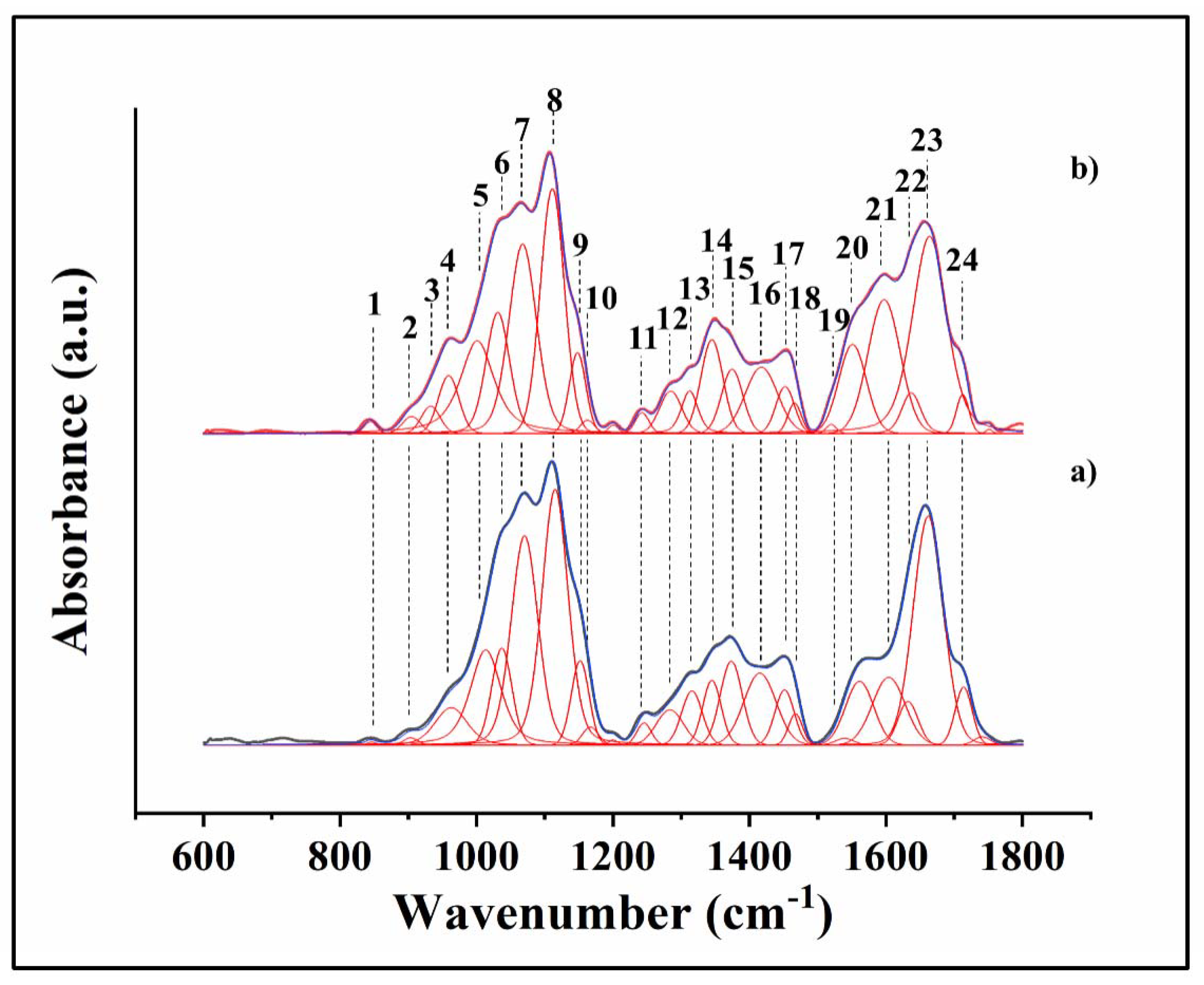
Figure 1. Photograph of the electrospinning system used.
Applsci 10 02360 g001
Figure 2. Water contact angle measurements on Ti-alloy and two Ti-alloy nanofiber-coated substrates (each sample labeled with a different color). Three substrates for each class were tested. CS: chitosan; BG: bioactive glass; PEO: polyethylene oxide.
Applsci 10 02360 g002
Figure 3. FTIR spectra of BG (a), CS (b), PEO (c), CS/PEO (d) and CS/PEO/BG (e) nanofibers. The labels, differently colored, indicate the most represented bands of BG (green), CS (red) and PEO (black).
Applsci 10 02360 g003
Figure 4. FTIR spectra of CS/PEO (a) and CS/PEO/BG (b) nanofibers. The numbers correspond to the positions of bands whose assignments are listed in Table 1.
Applsci 10 02360 g004
Figure 5. 3D laser micrographs of the three different substrates (Ti-alloy (a), CS/PEO (b) and CS/PEO/BG (c)) obtained before bacterial and osteoblast treatments at two different magnifications (10X and 150X).
Applsci 10 02360 g005
Figure 6. Comparison of roughness parameters, Ra and Rz of the substrates samples; the values are obtained calculating the parameter in 25 images collected at 150X on each surface substrates labeled with three different color (ns = non-significant; p < 0.05).
Applsci 10 02360 g006
Figure 7. SEM images (collected at 5000X magnification) and diameter distributions of the electrospun nanofiber coatings (CS/PEO (a,b) and CS/PEO/BG (c,d)). The diameter size distributions were obtained analyzing 200 fiber sizes on each surface.
Applsci 10 02360 g007
Figure 8. Images collected using EDX elemental maps pf CS/PEO (a) and CS/PEO/BG (b) converted in different colors (blue for calcium, green for silicon and red for carbon) and overlaid on the SEM images in order to verify the incorporation of bioglass inside the fibers. EDX maps and SEM images were collected at 5000X magnification.
Applsci 10 02360 g008
Figure 9. Experimental time-lapse results and statistical validation of (a) OD measurement related to Microbial viability assay and (b) CFU counting on the three substrates labeled with three different colors.
Applsci 10 02360 g009
Figure 10. Fluorescence micrographs after PI, CFDA, and DAPI staining of S. epidermidis exposed for 12 h to: (a) Ti-alloy, (b) CS/PEO and (c) CS/PEO/BG. Live and dead cells are labeled with green and red stains, respectively, whereas nuclei display in blue color. Images were obtained at a 4X magnification.
Applsci 10 02360 g010
Figure 11. Fluorescence micrographs after PI, CFDA, and DAPI staining of S. epidermidis exposed for 48 h to: (a) Ti-alloy, (b) CS/PEO and (c) CS/PEO/BG. Live and dead cells are labeled with green and red stains, respectively, whereas nuclei display in blue color. Images were obtained at a 4X magnification.
Applsci 10 02360 g011
Figure 12. SEM images of bone formation on the three substrates and EDX elemental maps labeled calcium (blue), carbon (red) and phosphorous (blue) to identify the presence of the mineral. SEM images were collected at 500X (Ti-alloy (a), CS/PEO (b), CS/PEO/BG (c)), while EDX maps and related SEM images were collected at 5000X.
Applsci 10 02360 g012
Figure 13. Fluorescence microscopy images collected on Ti-alloy (a), CS/PEO (b), and CS/PEO/BG (c) substrates: blue stain (osteoblast nuclei), red stain (osteopontin), and green stain (osteocalcin). Images collected at 4X.
Applsci 10 02360 g013
Table 1. List of FTIR band assignments related to CS/PEO and CS/PEO/BG.
NumberPosition (cm−1)AssignmentsReferences
1843CH2 rocking[38]
2900wagging (C-H)[28]
3934Si-O stretching[28]
4958CH2 rocking of methylene group [38]
5999CO group [39]
61029 (1034)stretching C-O, (Si-O stretching)[28,30,(36)]
71066symmetric and asymmetric stretching (C-O)[28,30]
81110Asymmetric stretching (C-O-C)[29]
91146Symmetric stretching (C-O-C)[28]
101159(carbonyl bands) bridge C-O-C[28,30]
111241Symmetric twisting CH2 [31]
121287Asymmetric twisting CH2[32]
131315C-N stretching, C-H symmetric stretching (CH3) (amide III)[28]
141348CH2 wagging (C-H)[31]
151374CH3 bending[28,30]
161420CH2 bending[28,30]
171456Asymmetric and symmetric CH2 bending[29]
181470Asymmetric CH2 bending[38]
191518N-H deformation and C-N stretching of amide II[34]
201557N-H bending (amide II)[35]
211595N-H bending[33]
221634N-H bending of NH2, C=N stretching (Schiff base)[40]
231663Stretching C=O (amide I)[34]
241713Carboxyl band (C=O) [35]

