Article

Mechanical Integrity Analysis of a Printed Circuit Heat Exchanger with Channel Misalignment

by
Armanto P. Simanjuntak
and
Jae Young Lee
*
Department of Mechanical and Control Engineering, Handong Global University, Pohang 37554, Korea
*
Author to whom correspondence should be addressed.
Appl. Sci. 2020, 10(6), 2169; https://doi.org/10.3390/app10062169
Submission received: 2 March 2020 / Revised: 17 March 2020 / Accepted: 18 March 2020 / Published: 22 March 2020

Abstract

:
Printed circuit heat exchangers (PCHEs), which are used for thermal heat storage and power generation, are often subject to severe pressure and temperature differences between primary and secondary channels, which causes mechanical integrity problems. PCHE operation may result in discontinuity, such as channel misalignment, due to non-uniform thermal fields in the diffusion bonding process. The present paper analyzes the mechanical integrity, including the utilization factors of stress and deformation under various channel misalignment conditions. The pressure difference of the target PCHE is 19.5 MPa due to the high pressure (19.7 MPa) of the steam channel in the Rankine cycle and the low pressure (0.5 MPa) of molten salt or liquid metal in the primary channel. Additionally, the temperature difference between channels is around 25 °C, however the average temperature is around 500 °C. The PCHE has a relatively large primary channel measuring approximately 3 x 3 mm, and a steam channel measuring 2 x 1.5 mm. The finite element method (FEM) is applied to determine the stress by changing the misalignment to below 30% of the primary channel width. It was found that the current PCHE is operable up to 700 °C in terms of the ASME code under these design conditions. Additionally, the change of utilization factor due to the misalignment increases, but is still under the ASME acceptance criteria of 700 °C; however, it violates the criteria at 725 °C, which is the allowable temperature condition. Therefore, the mechanical integrity of the PCHE with low-pressure molten salt or liquid metal and a high-pressure steam channel is acceptable in terms of utilization factor.

1. Introduction

Heat exchangers are devices that facilitate the exchange of heat between two fluids at different temperatures while keeping them from mixing together [1,2]. Heat exchangers are mostly used in processing, power, petroleum, air conditioning, refrigeration, alternate fuels, and other industries. Heat transfer in a heat exchanger usually involves convection in each fluid and conduction through the wall separating the two fluids. In general industry, heat exchangers can be classified according to their construction, transfer process, degree of surface compactness, flow arrangement, pass arrangement, phase of the process fluids, and heat transfer mechanism. The shell–tube type is the most popular heat exchanger for industry. However, printed circuit heat exchangers (PCHE) have shown promise because of their advantages, such as having large area density and good pressure and temperature capabilities [3,4,5].
High-efficiency compact heat exchangers are being widely developed and becoming increasingly important for the nuclear industry. The main target of such development is improvement of the efficiency, economics, and safety. Depending on the intended scale and application, different types are being considered, using fluids such as helium, supercritical carbon dioxide (S CO2), mixed nitrogen and helium nitrogen, liquid metals, and molten salts. All of these reactors are operated at high temperature. For example, sodium fast-cooled reactors (SFRs) and supercritical carbon dioxide (S CO2) reactors are operated at maximum temperatures of 550 °C. The only difference is the working pressures, which are 0.1 and 20 MPa, respectively, for these reactor types [6]. For these reasons, safety is an important feature of PCHEs because some critical issues can occur. Additionally, the development of high-efficiency plate heat exchangers is also important for thermal energy storage in alternative energy. Alternative technologies are being developed in order to save fossil resources and reduce air pollution by capturing and using renewable sources of energy, such as solar, wind, and hydropower, or geothermal heat. Thermal energy storage (TES) is a technology that stocks thermal energy by heating or cooling a storage medium, so that the stored energy can be used at a later time for heating and cooling applications and power generation. One of the issues with this is the thermo-structural fatigue, as observed by Rakesh et al. [7]. The thermal stresses have been found to be more dominant than stresses due to pressure cycles. This is due to the higher temperature gradient. Hence, safety has a strong relationship with high mechanical integrity and long operating life.
Much effort has been given to studying the thermo-hydraulic characteristics of PCHE channels. The thermo-hydraulic performance of PCHEs for SCO2, which contains helium as the fluid, was studied by Mylavarapu et al. [8]. There was a difference in the critical Reynold numbers due to the difference in the shape of the cross-section between the circular and semi-circular ducts. The thermo-hydraulic performance of a newly developed PCHE, which had a longitudinal corrugation flow channel, was studied by Kim et al. [9]. The friction factors tended to be greater when the PCHE had a smaller hydraulic diameter and a larger angle of inclination. Sung et al. conducted a study on heat exchangers for thermoelectric power generation. The shape of the cross-section was a combined rectangular and circular shape, with a developed tangled channel. The obtained result showed the increase of the heat transfer at a relatively lower Reynold number [10]. Yoon et al. conducted an assessment study of straight, zigzag, s-shape, and airfoil PCHEs for intermediate heat exchanger (IHX) of high temperature gas reactors (HTGR) and sodium-cooled fast reactors (SFR). The study suggests a best option named the Kalimer-600 IHX, which is a straight PCHE [11]. For this reason, improvement of the cross-section shape may enhance the thermo-hydraulic performance. Therefore, the mechanical integrity of the channel shape effect needs to be studied. A preliminary study on the mechanical integrity of the proposed design is needed and is the main purpose of this paper. Some studies on the structural integrity of PCHEs have also been conducted. Lee et al. studied the structural integrity of an intermediate printed circuit heat exchanger for a SFR attached to supercritical carbondioxide. It was found that the mechanical stress concentration occurred at the PCHE channel tip [12]. Song et al. also conducted a study on the structural integrity evaluation of a lab-scale intermediate PCHE in a very-high-temperature reactor (VHTR). Under the test conditions, the maximum Tresca stress was far below the allowable stress limit [13]. Mizokami et al. conducted a structural design study of a plate–fin heat exchanger for HTGRs. In this study, we present a high-temperature structural design procedure for a plate–fin heat exchanger, which includes strength evaluation for primary stress and evaluation of creep–fatigue life [14]. Mochizuki and Takano conducted a study on heat transfer in heat exchangers in sodium fast-cooled reactor systems. The practical Nusselt numbers of a heat exchanger were derived in the MONJU fast breeder reactor which was a Japanese sodium-cooled fast reactor [15].
The present study examined the stress distribution in a newly designed printed circuit heat exchanger model. This model is different to the common designs, which mainly use a semicircle channel shape. This shape is a combination of rectangular and ellipsoidal shapes, as shown in Figure 1. This PCHE design is planned to be manufactured through chemical etching and diffusion bonding processes. First, the canals that become the channel will be manufactured by chemical etching. Then, all layers will be stacked through diffusion bonding. In this case, the successful incorporation of a heat exchanger in a high-temperature nuclear service requires the manufacturer to be able to reliably produce high-quality diffusion welds. Because inspecting each weld in the core stack is impractical, the quality depends on a good understanding of the essential welding variables and strict control during the welding process [16,17]. In the diffusion bonding process, misalignment may occur due to improper process control related to the temperature or pressure. Even though this misalignment can be controlled by strict variable controls during the bonding process, it is also essential to observe the effects of misalignment at the microscale, so that the limit corresponding to the safety factor can be set. In this paper, the misalignment phenomena that may occur in PCHE channels are modeled and simulated. A two-dimensional simulation using COMSOL Multiphysics is conducted to observe the effect of channel misalignment on the mechanical integrity of PCHE. Different misalignment conditions are modeled to compare the stress intensities.
In addition to the structural integrity study, several previous studies have examined this misalignment problem. Weld misalignment influences the structural integrity of a cylindrical pressure vessel; in the most dangerous analysis case, a crack depth of 7 mm and allowable centerline offset of 8 mm resulted in a pressure limit of 3.15 MPa, which is still 0.65 MPa greater than the hydro test pressure [18]. Finite element analysis was conducted on cylindrical pressure vessels with a misalignment in a circumferential joint by Brabin et al. [19]. The results showed good agreement with [20]. The structural integrity of a steam generator tube sheet with an incorrectly drilled hole was evaluated according to ASME Section III construction code. The presence of incorrectly drilled holes or locally thin ligaments was found to not affect the primary stress margin in the tube sheet or reduce its overall structural integrity [21]. The finite element method (FEM) was used to investigate local stress concentrations due to the misalignment of welded structures and determine the effect of geometric variables. The existence of a cope hole was found to influence the peak stress surrounding the transition zone [22]. From all the previous research mentioned above, there has not been a study on the misalignment effect in PCHEs under high-temperature conditions. For this reason, this study investigates the structural integrity of the proposed geometry and the effect of the misalignment condition along the diffusion bonding line on the structural integrity of the PCHE. The structural integrity is represented by the utilization factor, which is the ratio of stress intensity to the maximum allowable stress for design conditions. Besides the utilization factor, displacement is also a main observed variable, which further includes the displacement value and displacement behavior under the applied load.
ASME Section III is taken as the reference construction code. The obtained stress distributions are used to evaluate the compliance with design criteria by using ASME Boiler and Pressure Vessel Code (BPVC), Section III. This code contains specific rules for construction of nuclear facility components. ASME Section III, Division 5 [23] is taken as the reference construction code, specifically Subsection HB, which covers metallic pressure boundary components. Subsection HB consists of Subpart A (HBA) for low-temperature service components and Subpart B (HBB) for elevated-temperature service components. Table 1 shows the values of maximum temperature for various classes of permitted materials. Subpart HBB is applicable for materials that is used at temperatures above Tmax. The maximum temperature of liquid sodium in SFR applications is 528 °C. Hence, subpart HBB is chosen as the construction code for this application. These rules are applicable to class A components, regardless of the type of contained fluid, such as water, steam, sodium, helium, or any other process fluids. The obtained stress distribution will be compared to the design loading parameters.

2. Numerical Simulation

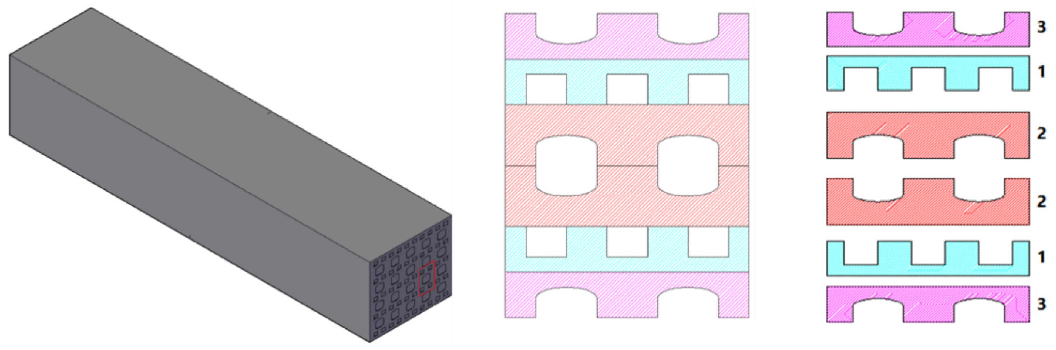
2.1. Approach and PCHE Design

The nuclear industry uses PCHEs as reactor components. PCHEs are used in advanced nuclear reactors because they offer a high surface-area-to-volume ratio, high thermal effectiveness, and low overall pressure drop, as mentioned in [24].
A PCHE is a steam generator and an important component of a sodium-cooled fast reactor. In a steam generator system, a countercurrent flow is formed by the sodium and steam flow. Steam is produced at inlet and outlet temperatures of around 230 and 503 °C, respectively, with inlet and outlet pressures of 18 and 16.7 MPa, respectively. Sodium flows at inlet and outlet temperatures of around 528 and 322 °C, respectively, with a pressure of 0.5 MPa [25].
Here, a new design for the printed circuit steam generator is proposed. Figure 1 shows a schematic drawing of the geometry, which consists of water and sodium channels. The sodium channel is surrounded by the water channel. The water channel is rectangular with 0.1 mm fillets. The sodium channel is semi-rectangular with an ellipsoidal diameter ratio of 0.5 mm to 3 mm.

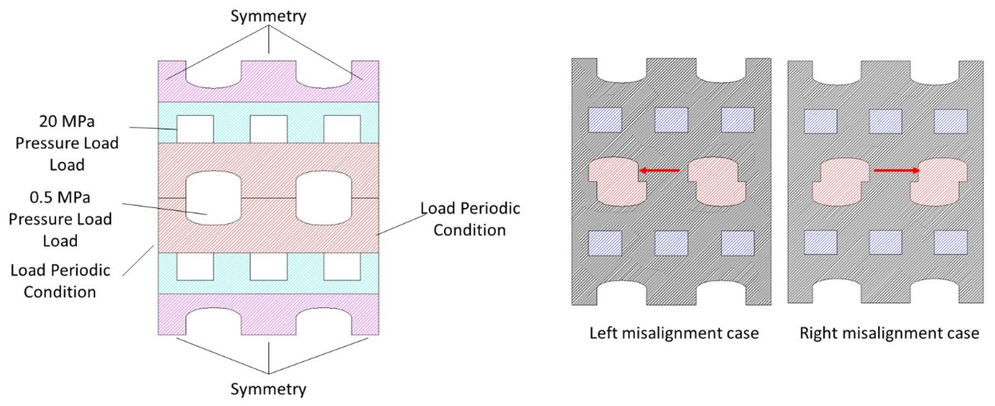
2.2. Boundary Conditions

A two-dimensional simulation using COMSOL Multiphysics was conducted with the proposed geometry. Table 2 lists the five different cases that were simulated to represent the possible misalignments due to a diffusion bonding discontinuity. The largest simulated misalignment was 1 mm, while the smallest was 0 mm, representing a perfect bond.
Figure 2 shows the applied boundary conditions for the numerical simulation. The boundary pressure load was used as the boundary condition. The load-controlled stress limit was analyzed. For comparison to the construction code, only the primary stress produced by a mechanical load was considered. Boundary loads of 20 and 0.5 MPa were applied to the water and sodium channels, respectively.

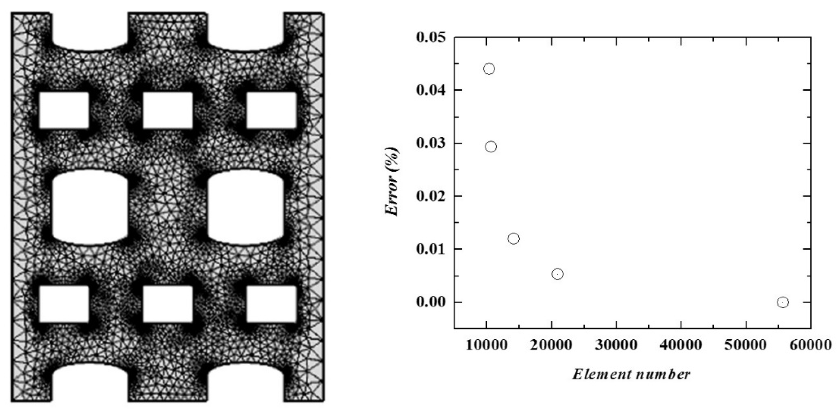
2.3. Mesh Independent Test

A mesh independent test was conducted to validate the geometry and mesh construction. Figure 3 shows the test and results. The number of elements was varied, and the surface average stress intensity was measured. The error was determined by subtracting the stress intensity from the highest stress intensity. The mesh sensitivity showed that the results converged for different numbers of elements.
A mesh independent test was conducted to validate the geometry and mesh construction. Figure 3 shows the test and results. The number of elements was varied and the surface average stress intensity was measured. The error was determined by subtracting the stress intensity from the highest stress intensity. The mesh sensitivity showed that the results converged for different numbers of elements. Here, 10,705 mesh elements were used in this simulation, with an average element quality of 79.9%. The elements were triangular elements, with a minimum element size of 0.0045 mm.

3. Results and Discussion

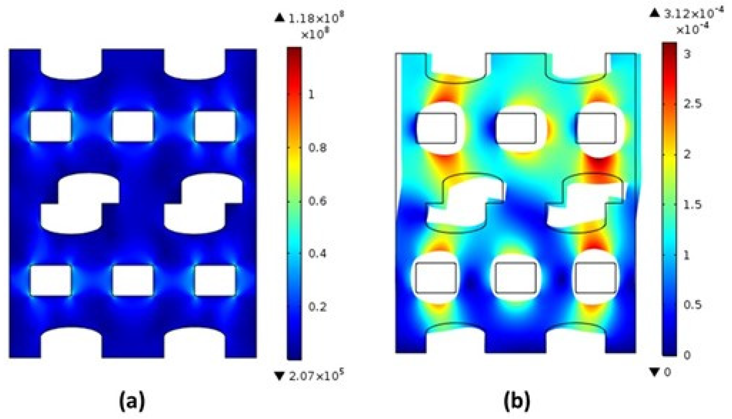
3.1. Stress Distribution at the Surface

2D stress distribution resulted by FEA simulation in the misalignment case of 0.85 mm is shown in Figure 4. The simulation result indicates that the highest stress intensity occurs at the tip area of the water channel. In the ten cases, the highest stress was in the tip area of the water channel. This was due to the higher pressure load in the water channel area. The maximum equivalent surface von Mises stress is shown in Figure 5. The highest maximum stress intensity was observed under the misalignment condition of 0.85 mm, while the lowest intensity was observed under the misalignment condition of 0 mm. This result indicates that the maximum stress distribution increases with the misalignment. The maximum stress intensity in the case of 0.85 mm misalignment is 10% higher compared to the 0 mm misalignment condition.

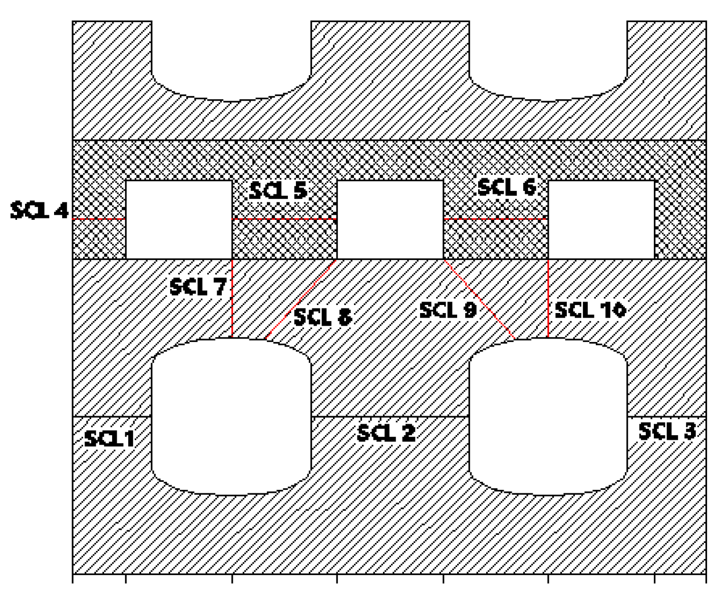
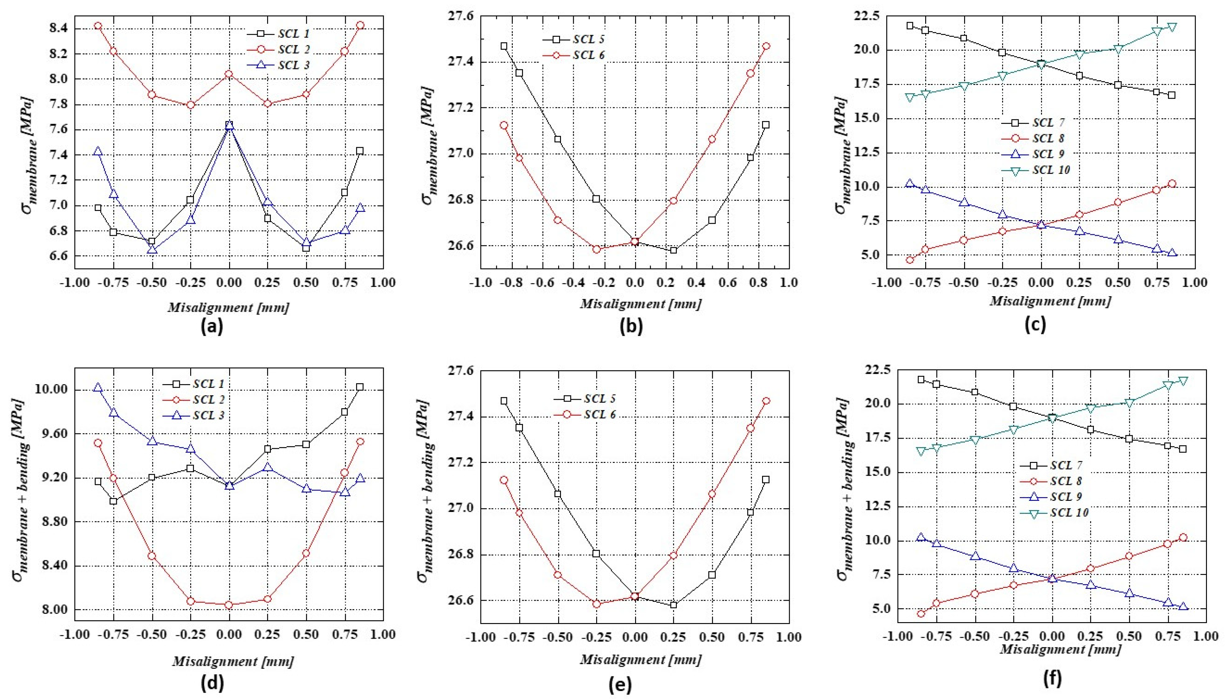
3.2. Stress at Stress Classification Line (SCL)

The main standard for the design of nuclear equipment is American Society of Mechanical Engineers (ASME) Boiler and Pressure Vessel (BPVC) section III. ASME code section III has specific requirements on how to assess the result from the stress analysis to make the necessary verifications to avoid failure. In this work, PCHE is classified as “safety-related” components associated with metallic components used in the construction of high-temperature reactor systems. For this problem, ASME Section III, Division 5, Subsection HB, Subpart B, which covers elevated temperature service components, is considered as the construction code.
In this study, finite element analysis is utilized to analyze and obtain the stress intensities. In order to comply with design codes stated in ASME section III, the stress linearization method is needed. Stress linearization is a technique used to decompose actual stress distribution across thickness into membrane and bending stress. This technique is stated in ASME Section VIII, Division 2 [26]. The stress linearization method is done by following the statement given by ASME VIII below.
The membrane stress tensor is the tensor comprised of the average of each stress component along the stress classification line, or:
σ ( i j , m ) = 1 t 0 t σ i j   d x
The bending stress tensor is the tensor comprised of the linear varying portion of each stress component along
σ ( i j , b ) = 6 t 2 0 t σ i j   ( t 2 x )   d x
The equivalent stress can be calculated by
σ e = [ σ x 2 + σ y 2 + σ x σ y + 3 τ x y 2 ] 1 / 2
To obtain the linearization result, stress classification lines (SCLs) are necessarily needed. Stress classification lines should represent the areas of interest of the proposed geometry, such as the sodium-to-sodium area, steam-to-steam area, and sodium-to-steam area. For this purpose, 10 SCLs have been taken throughout the geometry as shown in Figure 6 below.
Numerical simulation using COMSOL Multiphysics 5.3 resulted in 10 linearized stress values as shown in Figure 6. Linearized stress values between sodium channels are represented by SCL 1, SCL 2, and SCL 3. The interest areas between steam channel stress values are represented by SCL 4, SCL 5, and SCL 6. SCL 7–10 represent areas between steam and sodium channels. The linearization results are shown in Figure 7.
The linearization results are compared with the ASME Section III stress value requirements for design load conditions. For design load conditions, a variable named So is needed. So is the maximum allowable value of the general primary membrane stress intensity for use as a reference for stress calculation under design loading. For the load-controlled stress limit under the design limit, two equations are used for compliance
PmSo
PL + Pb ≤ 1.5So
where Pm is the general primary membrane stress intensity resulted by linearization along the SCLs and PL + Pb is the combined primary membrane stress intensity and bending stress intensity. Therefore, values decrease with the increase of working temperature, as shown in Figure 8. The proposed system aims to be used in sodium fast-cooled reactor wherethe maximum working temperature of a steam generator heat exchanger is 550 °C. Therefore, for this purpose the maximum allowable stress (So) should be set at 88 MPa. Hence, the 1.5So will be 132 MPa. The maximum resulting value using the linearization method is 27.5 MPa for the primary membrane stress intensity and 32.8 MPa for the combined primary membrane and bending stress intensity. These values are obtained from linearization along SCL 6. Both conditions are found in the 0.85 mm misalignment condition. The condition without any misalignment resulted in the highest stress intensity values of 26.6 MPa and 31.5 MPa for primary membrane stress and combined primary and bending stress, respectively. Compared to the requirements of the design condition, all misalignment conditions for the sodium channel still comply with the acceptance criteria. This means the misalignment condition for the sodium channel does not have too much of an impact on the acceptance criteria. However, deeper analysis of the utilization factor is performed to observe the effects of this misalignment condition.

3.3. The Utilization Factor Increases as the Misalignment Increases

The linearization method stress intensity values along the SCLs are still acceptable compared to the requirements of ASME III design conditions. However, deeper analysis should be done to observe the real effects of this misalignment condition. One of important factors in design and manufacturing is the utilization factor. Utilization factor is defined as the ratio of the worst condition to the acceptable condition. In this case, the ratio of the highest stress intensity resulting from the linearization method along SCLs and the So value are considered. The utilization factor is the ratio of the stress intensity resulting from linearization method along SCLs to the So as the minimum acceptable conditions.
Uf = σ/So
The graphs shown in Figure 9 below indicate that the utilization factor increased with the increase of misalignment of sodium channel conditions. The maximum utilization factor is shown with 0.85 mm misalignment with both negative and positive shifting. The conditions still maintain the utilization factor at 30% of the allowable value, which is the safe condition for design load application.
Since this proposed design is newly considered, the elevated temperature for other purposes should be considered. The utilization factor under elevated temperature (those exceeding 500 °C) is obtained, as shown in Figure 10. The figure shows that the condition of misalignment will be acceptable up to 725 °C. This means the application conditions above 725 °C cannot comply with the misalignment condition of 0.85 mm. This suggests that this proposed design can comply with the requirements of the ASME code for system applications under 725 °C.

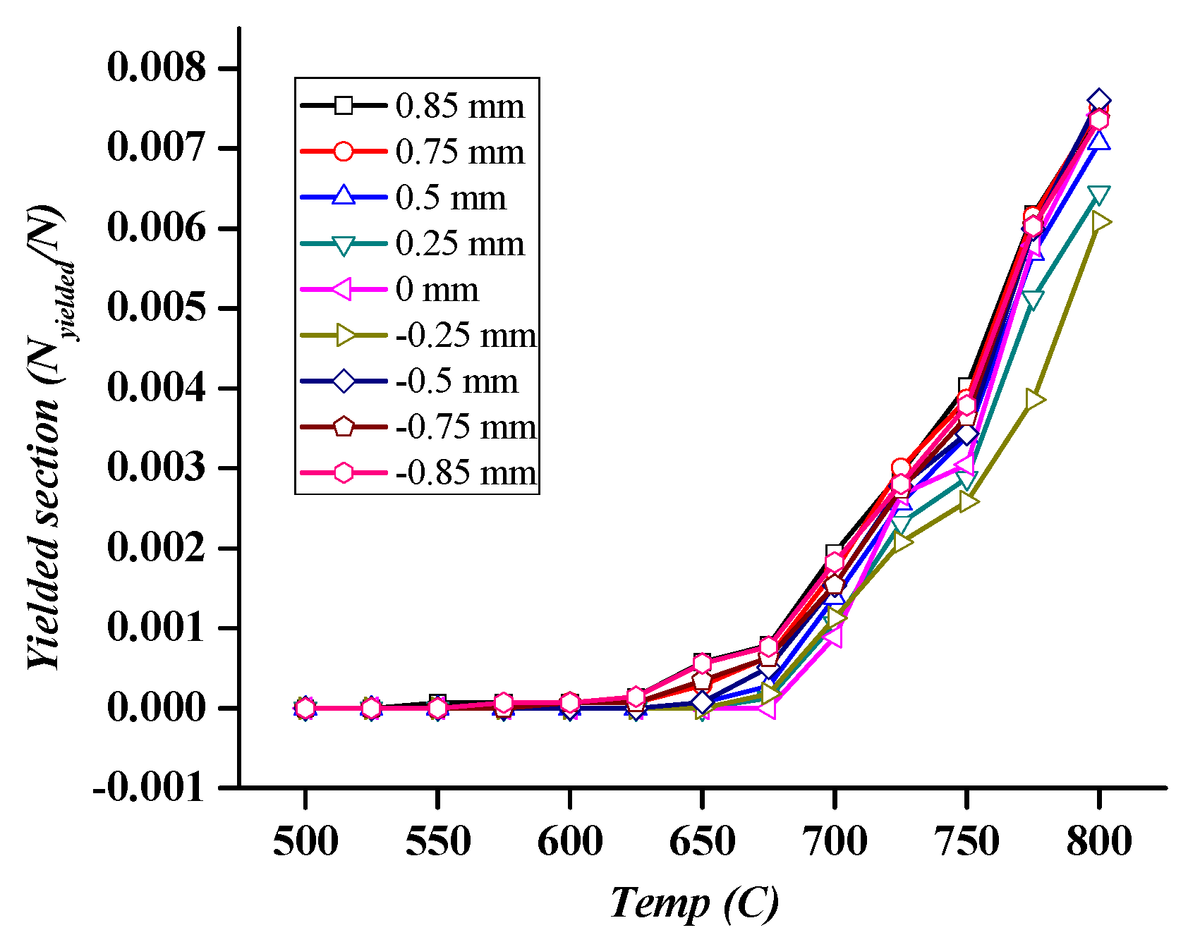
3.4. Yielding Section under Design Loading

The yield strength or yield stress is a certain stress magnitude at which the material begins to deform plastically. Below the yield stress, the material deforms elastically and returns to its original shape when the applied stress is removed. Once the stress magnitude passes the yield stress, the material deforms permanently, which cannot be reversed. In this model, stainless steel 316 (SS31600) was set as the material. In this case, it is assumed that diffusion welds have the same material properties as the base metals. At a temperature of 550 °C, the yield stress (Sy) of SS31600 is 116 MPa as shown in Figure 11 [27]. This indicates that no section in the simulated cases yielded due to the applied pressure load under a working temperature of 550 °C. However, if a higher temperature condition is considered for application, yielding may occur on the surface. As shown in Figure 12, yielded section increases above 625 °C.

4. Conclusions

In this study, two-dimensional FEM simulations were performed to observe the effects of primary channel misalignment in the PCHE under five different misalignment conditions.
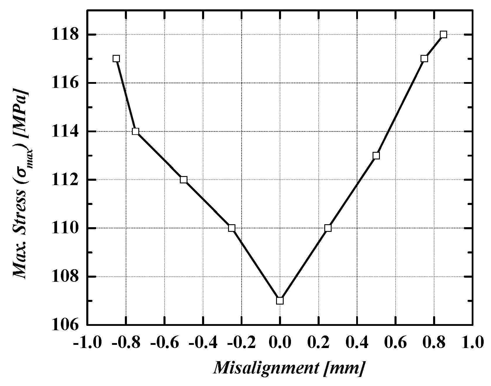
  • The highest stress intensity was located at the tip edge of the water channel for the higher-pressure intensity compared to that in the sodium channel;
  • The stress intensity increases as the misalignment increases, causing the utilization factor to increase, which is less safe compared to the condition without misalignment;
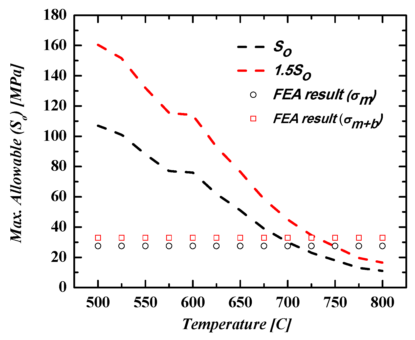
  • The proposed geometry design can comply with the design limit condition up to 700° C in terms of the ASME code. This means the for the SFR application, which has an average temperature of 550° C, the geometry design can comply with the design limit conditions. However, the design can comply with the acceptance criteria up to 725° C under 30% misalignment condition;
  • The study shows that the design of PCHEs needs to be more precise regarding welding and assembly processes, due to decreasing utilization factor. More strict construction and assembly process monitoring, especially during stacking and welding processes, is needed to avoid this utilization factor degradation due to misalignment conditions.

Author Contributions

Conceptualization, A.P.S. and J.Y.L.; methodology, A.P.S.; software, A.P.S.; validation, A.P.S. and J.Y.L.; formal analysis, data curation, A.P.S.; writing—original draft preparation, A.P.S.; writing—review and editing, A.P.S. and J.Y.L.; visualization, A.P.S.; supervision, J.Y.L. All authors have read and agreed to the published version of the manuscript.

Funding

This work was supported by the National Research Foundation of Korea (NRF) grant, funded by the Korea government (MSIP) (No. 2017M2A8A4018624).

Conflicts of Interest

The authors declare no conflict of interest.

Nomenclature

Abbreviations
ASMEAmerican Society of Mechanical Engineers
PCHEPrinted Circuit Heat Exchanger
FEMFinite Element Method
SCO2Supercritical Carbon dioxide
SFRSodium Fast-cooled reactor
TESThermal Energy Storage
IHXIntermediate Heat Exchanger
HTGRHigh-Temperature Gas Reactor
SCLStress Classification Line
Symbol
SmThe Lowest Stress Intensity value at a given temperature
KFactor K
SoMaximum allowable stress intensity
SmtMaximum allowable stress intensity value time dependent
PmPrimary membrane stress intensity [MPa]
PLPrimary membrane stress local [MPa]
PbPrimary bending stress [MPa]
UfUtilization factor as the ratio of stress intensity to the maximum allowable stress
mMisalignment case (mm)
σij,mMembrane Stress
σij,bBending Stress
σeEquivalent Stress
σxStress tensor in x direction
σyStress tensor in y direction
σzStress tensor in z direction
SyYield Stress

References

  1. Ҫengel, Y.A. Heat Exchanger. In Heat Transfer a Practical Approach, 2nd ed.; McGraw Hill: New York, NY, USA, 2004; pp. 667–704. [Google Scholar]
  2. Thulukkanam, K. Heat Exchangers Introduction, Classification, and Selection. In Heat Exchanger Design Handbook, 2nd ed.; CRC Press: New York, NY, USA, 2013; pp. 1–34. [Google Scholar]
  3. Asadi, M.; Xie, G.; Sunden, B. A review of heat transfer and pressure drop characteristics of single and two phases microchannel. Int. J Heat Mass Transf. 2014, 79, 34–53. [Google Scholar] [CrossRef]
  4. Chen, M.; Sun, X.; Christensen, R.N.; Shi, S.; Skavdahl, I.; Utgikar, V.; Sabharwall, P. Experimental and numerical study of a printed circuit heat exchanger. Ann. Nucl. Energy 2016, 97, 221–231. [Google Scholar] [CrossRef] [Green Version]
  5. Chen, M.; Sun, X.; Christensen, R.N.; Shi, S.; Skavdahl, I.; Utgikar, V.; Sabharwall, P. Pressure drop and heat transfer characteristic of a high-temperature printed circuit heat exchanger. Appl. Therm. Eng. 2016, 108, 1409–1417. [Google Scholar] [CrossRef] [Green Version]
  6. Li, X.; Le Pierres, R.; Dewson, S.J. Heat Exchanger for the next generation of Nuclear reactors. In Proceedings of the International Congress on Advances in Nuclear Power Plants, Reno, NV, USA, 4–8 June 2006; pp. 201–209. [Google Scholar]
  7. Patil, R.; Anand, S. Thermo- structural fatigue analysis of shell and tube type heat exchanger. Int. J. Press. Vessel. Pip. 2017, 155, 35–42. [Google Scholar] [CrossRef]
  8. Mylavarapu, S.K.; Sun, X.; Glosup, R.E.; Christensen, R.N.; Patterson, M.W. Thermal Hydraulic Performance testing of Printed Circuit heat exchangers in a high-temperature helium test facility. Appl. Therm. Eng. 2014, 65, 605–614. [Google Scholar] [CrossRef]
  9. Kim, J.H.; Baek, S.; Jeong, S.; Jung, J. Hydraulic Performance of a microchannel PCHE. Appl. Therm. Eng. 2010, 30, 2157–2162. [Google Scholar] [CrossRef]
  10. Sung, J.; Lee, J.Y. Effect of tangled channels on the heat transfer in a printed circuit heat exchanger. Int. J. Heat Mass Transf. 2017, 115, 647–656. [Google Scholar] [CrossRef]
  11. Yoon, S.H.; No, H.C.; Kang, G.B. Assessment of straight, zigzag, S-shape, and airfoil PCHEs for intermediate heat exchangers of HTGRs and SFRs. Nucl. Eng. Des. 2014, 270, 334–343. [Google Scholar] [CrossRef]
  12. Lee, Y.; Lee, J.I. Structural assessment of intermediate printed circuit heat exchanger for sodium-cooled fast reactor with supercritical CO2 cycle. Ann. Nucl. Energy 2014, 73, 84–95. [Google Scholar] [CrossRef]
  13. Song, K.N.; Hong, S.D. Structural Integrity Evaluation of a Lab-Scale PCHE Proto-type under the Test Conditions of HELP. Sci. Tech. Nucl. Install. 2013, 2013, 520145. [Google Scholar] [CrossRef] [Green Version]
  14. Mizokami, Y.; Igari, T.; Kawashima, F.; Sakakibara, N.; Tanihira, M.; Yuhara, T.; Hiroe, T. Development of structural design procedure of plate-fin heat exchanger for HTGR. Nucl. Eng. Des. 2012, 255, 248–262. [Google Scholar] [CrossRef]
  15. Mochizuki, H.; Takano, M. Heat transfer in heat exchangers of sodium cooled fast reactor systems. Nucl. Eng. Des. 2008, 239, 295–307. [Google Scholar] [CrossRef]
  16. Nestell, J.; (MPR Associates, Inc., Washington DC, USA); Sham, T.L.; (Oak Ridge National Laboratory, Tennessee, USA). ASME Code Considerations for the Compact Heat Exchanger. Personal Communication. 2015. [Google Scholar]
  17. Miwa, Y.; Noishiki, K.; Suzuki, T.; Takatsuki, K. Manufacturing technology of Diffusion-bonded Compact Heat Exchanger (DCHE). Kobelco Tech. Rev. 2013, 32, 51–56. [Google Scholar]
  18. Kozak, D.; Konjatić, P.; Matejiček, F.; Damjanović, D. Weld Misalignment influence on the structural integrity of cylindrical pressure vessel. Struct. Integr. Life 2009, 10, 153–159. [Google Scholar]
  19. Brabin, T.A.; Christoper, T.; Rao, B.N. Finite Element analysis of cylindrical pressure vessels having a misalignment in a circumferential joint. Int. J. Press. Vessel. Pip. 2010, 87, 197–201. [Google Scholar] [CrossRef]
  20. Morgan, W.C.; Bizon, P.T. Comparison of Experimental and Theoretical Stresses at a Mismatch in a Circumferential Joint in a Cylindrical Pressure Vessel; Technical Note; Lewis Research Center: Cleveland, OH, USA, 1966. [Google Scholar]
  21. Gomez, E. ASME Section III Stress Analysis of a Heat Exchanger Tube Sheet with a misdrilled Hole and Irregular or Thin Ligaments. In Proceedings of the ASME 2013 Pressure Vessel and Piping Conference, Paris, France, 14–18 July 2013; pp. 1–8. [Google Scholar]
  22. Liu, X.; Song, W.; Yan, Z.; Qiang, W.; Pan, H. Misalignment effect on stress concentration of thickness mismatched plate structures. Proc. Str. Integr. 2016, 2, 2038–2045. [Google Scholar] [CrossRef] [Green Version]
  23. ASME. An International Code 2015 ASME Boiler & Pressure Vessel Code Section III. Rules for Construction of Nuclear Facility Components Division 5 High Temperature Reactors; The American Society of Mechanical Engineer: New York, NY, USA, 2015. [Google Scholar]
  24. Bartel, N.; Chen, M.; Utgikar, V.P.; Sun, X.; Kim, I.H.; Christensen, R.; Sabharwall, P. Comparative analysis of compact heat exchangers for application as the intermediate heat exchanger for advanced nuclear reactors. Ann. Nucl. Energy 2015, 81, 143–149. [Google Scholar] [CrossRef] [Green Version]
  25. Yoo, J.; Chang, J.; Lim, J.Y.; Cheon, J.S.; Lee, T.H.; Kim, S.K.; Lee, K.L.; Joo, H.K. Overall System Description and Safety Characteristics of Prototype Gen IV Sodium Cooled Fast Reactor in Korea. Nucl. Eng. Tech. 2016, 48, 1059–1070. [Google Scholar] [CrossRef] [Green Version]
  26. ASME. An International Code 2015 ASME Boiler & Pressure Vessel Code Section VIII. Rules for Construction of Pressure Vessel Division 2; The American Society of Mechanical Engineer: New York, NY, USA, 2015. [Google Scholar]
  27. ASME. An International Code 2015 ASME Boiler & Pressure Vessel Code Section II Part D. Materials; The American Society of Mechanical Engineer: New York, NY, USA, 2015. [Google Scholar]
Figure 1. The schematic illustration of the printed circuit heat exchanger (PCHE).
Applsci 10 02169 g001
Figure 2. Applied boundary conditions for numerical simulation.
Applsci 10 02169 g002
Figure 3. Mesh sensitivity test.
Applsci 10 02169 g003
Figure 4. Huber–von Mises stress (a) and total displacement (b) distribution due to pressure load (at misalignment of 0.85 mm).
Applsci 10 02169 g004
Figure 5. Maximum stress intensity for each misalignment condition.
Applsci 10 02169 g005
Figure 6. Stress classification lines (SCLs) for stress linearization method.
Applsci 10 02169 g006
Figure 7. Primary membrane stress for various misalignment conditions: (a) sodium to sodium channel; (b) steam to steam channel; (c) between steam and sodium channels; And combined membrane and bending stress: (d) between sodium channel; (e) between steam channel; (f) between steam and sodium channels.
Applsci 10 02169 g007
Figure 8. Stress classification line for stress linearization method.
Applsci 10 02169 g008
Figure 9. Increase of utilization factor as the increase of the misalignment condition: (a) compared to So; (b) compared to 1.5So.
Applsci 10 02169 g009
Figure 10. Maximum allowable misalignment (% of initial channel’s width) under various temperature conditions.
Applsci 10 02169 g010
Figure 11. Maximum stress for each misalignment condition compared to yield stress of material SS316.
Applsci 10 02169 g011
Figure 12. Yielded section under pressure loading for various temperature conditions.
Applsci 10 02169 g012
Table 1. Maximum temperature for various classes of permitted materials.
NoMaterialsTmax (°C)
1Carbon steel370
2Low alloy steel370
3Martensitic stainless steel370
4Austenitic stainless steel425
5Nickel–chromium–iron425
6Nickel–copper425
Table 2. Five Simulated misalignment cases. Misalignment is measured as the center-to-center distance along the x direction.
Case #Misalignment (m)
Right directionLeft direction
Case 10 mm-
Case 20.25 mm0.25 mm
Case 30.5 mm0.5 mm
Case 40.75 mm0.75 mm
Case 50.85 mm0.85 mm

