Article

A Design for SDN-Based Identifier–Locator Separation Architecture on IoT Networks

1
Division of General Studies, College of Liberal Arts and Interdisciplinary Studies, Kyonggi University, 154-42, Gwanggyosan-ro, Yeongtong-gu, Suwon-si 16227, Gyeonggi-do, Korea
2
Department of Computer Science and Engineering, Jeonju University, 303 Cheonjam-ro, Wansan-gu, Jeonju-si 55069, Jeollabuk-do, Korea
*
Author to whom correspondence should be addressed.
Appl. Sci. 2020, 10(6), 2144; https://doi.org/10.3390/app10062144
Submission received: 1 February 2020 / Revised: 13 March 2020 / Accepted: 16 March 2020 / Published: 21 March 2020
(This article belongs to the Special Issue Green Communications in Smart City)

Abstract

:

Featured Application

Green Communication in Smart City.

Abstract

In upcoming smart urban environments, various things can be interconnected, and the Internet of Things (IoT) can be used to construct a safer and more convenient urban environment. Things in the IoT need an addressing system that can uniquely identify each one; internet protocol (IP) addresses can be used for this purpose. The IP address the two roles of an identifier and a locator. However, this binding has problems related to mobility and multihoming, and it is hard to deploy on a legacy IP system because of some limitations of sensor devices. To solve the problem, we propose a design for software-defined networking (SDN)-based identifier–locator separation architecture on IoT networks. In the proposed scheme, Internet Protocol version 6(IPv6)-based addresses are used for the identifiers and locators. The network is partitioned into a host identity domain for local routing and an IP domain for global routing. The host identity domain operates as an overlaid network over the IP domain, and it makes the unrouteable identifiers routable with a distributed hash table (DHT)-based routing strategy. For the evaluation of the proposed scheme, a packet forwarding cost and signaling cost model is calculated, and the results show that the proposed scheme is conjugable to an IoT network environment.

1. Introduction

Network environments are rapidly changing from wired access to wireless and mobile access network environments. As the number of mobile devices are increasing and the mobile market is growing explosively, mobility becomes one of the essential factors in mobile environments. Especially in the Internet of Things (IoT), one of the major technologies of the fourth industrial revolution, these mobile and sensor devices equipped with network functions are mainly used to collect data and extract valuable information such as temperature change, fire detection, and motion sensing from the data.
The IoT is generally referred to the technology for connecting various objects to the internet and networks. IoT devices can communicate with others and transmit data via embedded communication and sensing devices to those objects. The Internet of Things is used not only to connect things to a network but also to control things through sensors and to analyze data collected from things. In particular, in upcoming smart urban environments, such as smart cities and smart factories, various things can be interconnected to send and receive a lot of information, and the IoT can be used to construct a safer and more convenient urban environment based on the collected and abstracted data [1,2,3,4].
Things connected to the IoT need an address system that can uniquely identify each one in the network; therefore, devices are able to use internet protocol (IP) addresses as their identifiers (IDs) and locators (LOCs) to communicate with others and to bind a host and an application in the network. This binding provides some advantages for a wired and fixed network environment because the internet was originally designed for a fixed environment. Although it is important to consider the mobility function in today’s network environment, this binding still has several drawbacks such as mobility, multi-homing, and extensibility problems.
The exponential increase of mobile devices especially causes the difficulties of deployment and addressing in networks. Additionally, it is hard to maintain the routing table size of a default free zone (DFZ). Therefore, binding is not suitable for current mobile-oriented network environments. To provide a mobility function with scalable routing and addressing, the ID and LOC roles of IP addresses need to be separated for the future internet.
Thus, ID–LOC separation protocols have been proposed [5,6,7,8,9,10]. These proposed protocols use two namespaces as ID and LOC, and they are classified into two types: host-based protocols and network-based protocols. Host-based protocols, such as host identity protocol (HIP) and Shim6, require the modification of a protocol stack within the hosts and a rendezvous server for maintaining ID and LOC mapping information. Additionally, it has the problem of initial deployment in a network. In contrast, network-based schemes do not modify hosts’ protocol stack [8,9]. The end nodes do not participate in any signaling procedure. The ID–LOC mapping is processed by other network components such as routers, and they forward packets using tunneling according to the mapping information. The problems are bandwidth waste and processing overhead on the network caused by tunneling. Host-based and network-based protocols also require a centralized ID–LOC mapping system such as a rendezvous server and a map server. These problems cause the scalability problem.
In this paper, we propose a software-defined networking (SDN)-based identifier–locator separation architecture for IoT networks. In the proposed scheme, a distributed hash table (DHT)-based ID–LOC mapping management scheme is adopted [9,11]. The DHT is a kind of decentralized distributed system in which each node in the system holds key set such as <key, value > pairs. It is similar to a general hash table. The key sets are stored in a DHT, so the participating node can retrieve the value by using a given key. The basic features of a DHT are that it is decentralized, scalable, reliable, and fault resilient. Because of these characteristics, DHTs are generally used in peer-to-peer (P2P) and content distribution systems such as a BitTorrent.
SDN is defined as a conceptual architecture that encompasses various kinds of network technologies that are designed to make networks more flexible and agile [12,13]. SDN decouples the control plane and data forwarding plane from the network for enabling the network partitioning and immediate control. Also, it is able to be abstracted the underlying infrastructure for applications and network services. In SDN, it is possible to operate different routing mechanisms on physical and virtual networks, which makes networks more flexible. We focused on this feature to apply a DHT-based routing algorithm for a virtual network and an existing IP routing algorithm for a physical network. We adopted the routing algorithm and structure of a Content Addressable Network (CAN), which is one of the DHT-based routing algorithms, to route the endpoint identifier (EID).
In the proposed scheme, mobile or sensor nodes only send packets including an EID as their address to the network and do not participate in the ID–LOC converting procedure. The controllers maintain the EID–LOC mapping information to forward to the destination. Additionally, the controllers send a command to their OpenFlow-enabled switches to configure their flow table entries for the packets. To manage the IDs and LOCs, we made up an overlaid network by borrowing a concept from the CAN in SDN [9,10,12,13]. In the proposed scheme, we used a field replacement function in the OpenFlow-enabled switches (OFSs) to reduce tunneling overheads.
This paper is organized as follows. Section 2 presents existing research, schemes, and practical examples. Section 3 introduces the proposed scheme with each operation process. In Section 4, we illustrate the cost model and calculate the packet forwarding and signaling cost. Section 5 provides results and discussions, and, finally, Section 6 illustrates the conclusion and future works.

2. Related Work

2.1. Existing Project in the Field

In recent years, various studies have been conducted to attempt to change network systems by using SDN. For example, Cisco has been conducting research on location and identifier separation and research on SDN in line with the paradigm shift of the network for several years [14]. Recently, with the increase of IoT devices, Cisco is having been preparing for processing rapidly increasing network traffic. In addition, Cisco has been developing a network solution with SDN that can be applied to various places and industries where IoT devices are used, such as enterprises, factories, warehouses, and healthcare areas. Another company, Spirent communication, has also been developing an SDN network solution [15]. For the development of the SDN network solution, Spirent has been working to provide a more stable and efficient network solution by conducting various studies and tests through the development of network function virtualization (NFV), OpenFlow switched network and path computation element protocol.

2.2. Host-Based Identifier–Locator Separation Schemes

For separating the ID and LOC roles of an IP address, several protocols have been proposed. These protocols are divided into host-based protocols such as Host Identity Protocol (HIP), shim6, and Mobile Oriented Future Internet (MOFI), and network-based protocols such as the Locator Identifier Separation Protocol (LISP) and DHT-based scheme [5,6,8,16,17,18].
HIP, a representative host-based ID–LOC separation protocol, introduced new namespaces for separating the ID and LOC of a host. It suggests to add a host identity layer between the IP layer and the transport layer. The host identity layer communicates with the upper layer using a host ID as an identifier and a lower layer using an IP address for the locator. This layer maintains the mapping information between identifiers and locators [5]. Shim6 provides site multihoming by Internet Protocol version 6 (IPv6) intermediation. It suggested a multihoming shim layer called l3shim within the IP layer for the local agility with failover capabilities. The basic concept of Shim6 is similar to HIP, but it does not use a special namespace such as a host ID and locator in HIP. A host of Shim6 allows for multiple IPv6 address prefixes to continue existing communication [6]. MOFI also uses a host ID (HID) for ID and an LOC for a locator. However, MOFI uses two kinds of LOCs as a locally routable LOC that must only be locally unique in an access network (A-LOC) and an LOC that is used in the backbone network (B-LOC). Each access router (AR) within MOFI operates the LOC translation between the A-LOC and B-LOC. For the maintenance of HID–LOC mapping, the AR includes a local mapping controller (LMC) with a hash table and HID–LOC register (HLR). The HID–LOC mapping information are managed in ARs in a distributed manner [16,17].
The weakness of host-based protocols is that every host has to modify its protocol stack. It makes the deployment of hosts difficult in a network. Additionally, they need a centralized mapping server to the ID–LOC mapping, so it may cause a single point of failure [9].

2.3. Network-Based Identifier–Locator Separation Schemes

In contrast, an LISP is a representative network-based ID–LOC separation protocol. An LISP enables the separation of IP addresses into two new numbering spaces. One is the endpoint identifiers (EIDs) that are not globally routable, and the other is routing locators (RLOCs) that are globally routable. Also, LISP defines an encapsulating mechanism for the LISP routers to transmit packets using EIDs across a network infrastructure that uses RLOCs. The routers are responsible to lookup the mapping between EIDs and RLOCs. In an LISP, packets to the destination through Ingress Tunnel Routers (ITRs) and Egress Tunnel Routers (ETRs). ITRs and ETRs are used as tunnel start and end points [8].
A DHT-based identifier–locator mapping scheme (DHT–MAP) was proposed to resolve an LOC for a flat ID [16]. The authors used a DHT-based system, which is a modified version of the CAN system. The CAN is a DHT-based network that uses to map “keys” onto “values.” The network consists of a customer network for forwarding packets and an overlay network using CAN for maintaining ID–LOC mapping. In this scheme, every autonomous system (AS) maintains one or more resolvers to store EID–LOC mapping. Network-based protocols, however, require the tunneling for forwarding packets. Because the use of tunneling needs an encapsulation and a decapsulation mechanism for processing the packets, it consumes more bandwidth and processing overhead.

2.4. SDN and OpenFlow

OpenFlow specification is generally introduced as the first standard protocol that is defined between control planes and forwarding planes of SDN architecture. The Open Networking Foundation (ONF) defines the SDN and OpenFlow specification [12,13]. OpenFlow enables a network to be programmable by decoupling the control plane and forwarding plane. OpenFlow is designed to directly manage and transfer traffic, so it enables an SDN controller to directly interact with the forwarding plane of network devices. By using OpenFlow, controllers can provide remote administration for switches by controlling flow tables. By controlling the flow table, OpenFlow can enable a network to respond to real-time changes. OpenFlow specification introduces the packet format and actions based on the rules [19].
Recently, a study was introduced to provide effective flow table management in SDN networks [20]. SDN technology is used in many areas for the flexibility and scalability of networks. Therefore, the size of the flow table to be handled by the OpenFlow switch and controller can be gradually increased. In [20], the authors proposed a hash-indexed wildcard scheme. The proposed scheme only keeps the index value of the matched flow of the wildcard-based flow table. It does not store entire flow information in a hash-based flow table; instead, it stores the location of the flow entry that exists in the wildcard-based table. However, the authors only focused on flow table management in SDN-based cloud networks. They did not consider IoT network environments.

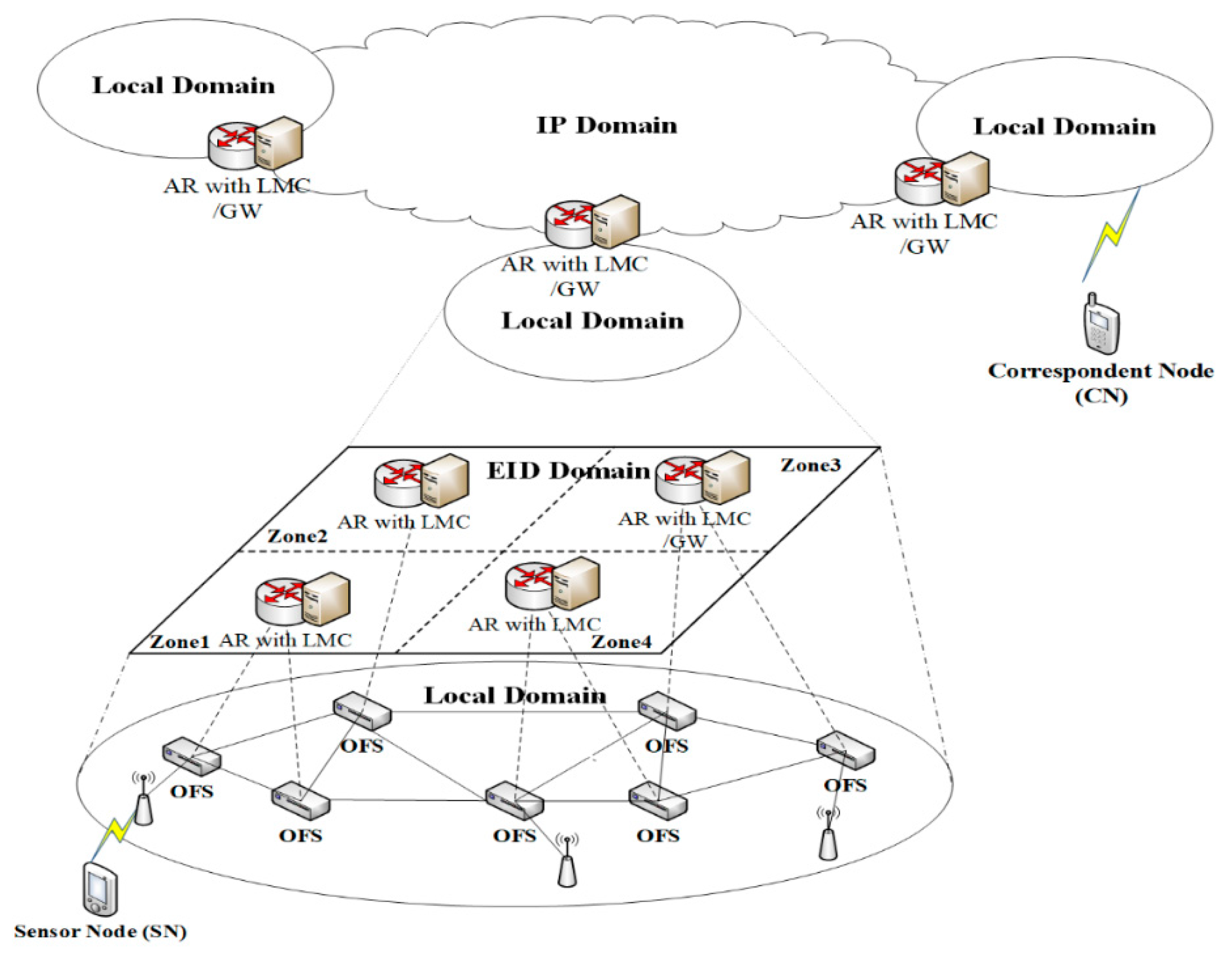
3. Proposed SDN-Based Identifier–Locator Separation Architecture for IoT Networks

In this section, we introduce the architecture and the namespaces that are used in this paper. Each procedure for registration, packet forwarding, and route optimization are described with some examples. From now on, we use the term MN to indicate mobile nodes, sensor nodes, and endpoint nodes. In the proposed scheme, it is assumed that an MN can send and receive data using an IPv6 over low power wireless personal area network (6LoWPAN) protocol [21,22].

3.1. EID and LOC

We use two namespaces for the roles of identifier and locator: EID and LOC, respectively. The EID is an unrouteable IPv6 address in an IP-based network, and it is generated by using the EID generating mechanism based on the work of [5,23,24,25]. According to [5,23], the EID is generated with the public key of an asymmetric key pair of the node. The EID, which is used in protocols to represent the sensor node’s identity, is a hashed encoding value of the identifier of a sensor node. In the proposed scheme, an MN’s network access identifier (NAI) is used for generating an EID instead of using the public key of an MN. The LOC is a routable IPv6 address that is used as a general IP address in IP-based networks and is generated by using the current network prefix with an MN’s media access control (MAC) address based on the address autoconfiguration mechanism to indicates the current location of the MN to which it is attached.

3.2. Proposed Architecture

In the proposed scheme, the underlying network is partitioned into a local EID domain and a global IP domain, and the network consists of OpenFlow-enabled switches (OFSs) and access routers (ARs) that are equipped with the functions of SDN controllers. The network resource is virtualized to accommodate the local EID domain and global IP domain. Figure 1 shows the proposed network architecture in which the local domain is overlaid onto the IP domain.
LOCs, the global addresses, are transmitted via the IP domain by using common IP routing, through ARs with a local mapping controller (LMC) [26,27]. The general IPv6 address packets are forwarded to a destination as in SDN environments. In contrast, the local EID domain is used to deliver packets that have the address field with an EID. The local EID domain is a virtual d-dimensional Cartesian coordinate space as shown in a DHT-based CAN network [11]. The EID domain is logically overlaid over the IP network and bears no relation to any physical coordinate system.
In the EID domain, the virtual coordinate space is used to store and maintain the < EID, LOC > pairs on the controller. The entire virtual coordinate space is dynamically divided into the number of controllers in the system. All EIDs are distributed to EID blocks consisting of blocks, the number of which is equal to the number of zones, and each EID block is assigned to each zone. An AR with an LMC is located in each zone, and each AR is responsible of taking care of the allocated EID block and MNs that have EIDs. Also, these ARs are responsible to register EID–LOC mapping information. All ARs of the local EID domain own their individual, distinct zone within the space, and they manage the <EID, LOC> pairs using the DHT mechanism. The ARs have the following functions: first, network attachment detection; second, mapping the LOC to the EID of the MNs and updating the EID–LOC mapping; third, mapping information maintenance and management; and last, flow table configuration for EID routing.
PMIPv6 assumes that a link layer protocol notifies the mobile access gateways (MAGs) about the MN’s identifier to detect the MN’s attachment and to acquire the MN’s identifier when the L2 authentication process is finished. The same assumption of the detecting an MN in the PMIPv6 is utilized in the proposed scheme. After the detecting process, the generation of the MN’s EID and LOC is possible at ARs.
For the maintenance and updating of EID–LOC mapping information, the local EID domain utilizes key registration, lookup, and routing mechanisms from the CAN [11]. When an AR detects an MN’s attachment, the AR is able to generate an MN’s EID and LOC, and < E I D M N , L O C M N > pair. The AR stores the < E I D M N , L O C M N > pair to its binding cache only if the E I D M N is included in the range of an EID block that is maintained by itself. In this case, the EID has a responsibility for maintaining this MN and replying to the corresponding LOC when the other ARs request the LOC of the MN. If the E I D M N is located outside the range of the attached AR’s EID block, the AR stores the binding information in its binding update list. After that, the AR registers the < EID, LOC > pair to the AR that is responsible to maintain that pair. The updating procedure is also similar.
All the ARs in the system have to preconfigure the flow table of their OFSs. Through this pre-configuration, the ARs can obtain the route for the EID packets to the nearest zone to get the destination of the packet, and OFSs are able to forward EID packets to OFSs of the nearest zone.

3.3. Operations of ARs and OFSs

The ARs are classified by three roles. The first role is a home AR (h_AR) for an MN. If an MN’s EID is included in an AR’s EID block, this AR becomes an h_AR of the MN. The h_AR has to manage the EID–LOC mapping information, and it has the responsibility to send the corresponding LOCs for the EID queries. Second, it manages a zone in which an MN is physically located. In this case, the role of the AR becomes the serving AR (s_AR). When the s_AR detects the attachment of a new MN, it assigns an LOC for the EID of this MN and maintains the mapping information. It also announces and updates this EID–LOC binding information to the MN’s h_AR. If an MN with an EID tries to send a packet to a corresponding node (CN) having EID, the s_AR sends a query that gets the LOC of a CN to prepare IP routing. Once the s_AR obtains the MN and the CN’s LOC, it sets the flow tables of its OFSs. The last role of an AR is to act as a neighbor EID controller (n_AR). The ARs between the h_AR and the s_AR are regarded as n_ARs. The n_ARs just forward received packets to the nearest zone of the destination according to the preconfigured flow table for EID routing. Generally, OFSs forward the received packets based on the matching rules of its flow table. If there is no matching from the received packet, the OFS sends this packet to its AR. Otherwise, it performs proper process according to the rule.
In the proposed scheme, the OFS connected to an MN has a function that converts LOCs to EIDs for the destination address and vice versa. The physical paths of the local EID domain that overlap with the IP domain may not be optimized. The address field conversion of OFSs makes it possible to find the optimal paths over the IP domain and forwards the packet through the paths. The OFSs that are located between the OFSs connected to the MN and the CN are considered to be intermediate OFSs (iOFSs), and their basic role is forwarding the received packets to the OFSs of the nearest zone toward the destination.
Figure 1 describes the system architecture of the proposed scheme and packet flows using IP and EID routing. In Figure 1, the local EID domain is divided into four EID zones. Each zone is managed by an AR. The local EID domain is overlaid over the IP domain. The packets are practically forwarded on the IP domain. An example of packet forwarding on the architecture is also described in Figure 1. When an MN sends a packet to a CN, the addresses of the MN and the CN may be EID addresses or normal IP addresses. Assume that the MN and the CN use EID addresses. Then, the source and destination address in the packets become E I D M N and E I D C N , respectively. The packets from the MN are delivered from the OFS of the s_AR to the OFS of the h_AR. Since the s_AR’s OFS does not know the CN’s LOC, it sends the packets to the s_AR for EID routing.
The EID routing path, however, differs from the physical path of the physical zone because each AR manages more than the two OFSs within the zone. As we mentioned before, ARs preconfigure the EID routing path in their OFSs, and the EID packets are able to be forwarded by using the preconfigured EID routing path on an IP domain, even if the packets with EIDs are unrouteable on an IP domain. Therefore, the packets from the OFSs of the s_AR are forwarded to the OFS of the CN’s h_AR using EID routing via the iOFSs. Since the OFS of the CN’s h_AR already knows the mapping between the EID and the LOC of the CN, it replaces the destination filed from E I D C N to L O C C N immediately, and it sends the packet to the IP domain. When the OFS of the CN’s s_AR receives the packet, it can convert L O C C N to E I D C N and directly forward the packet to the CN.
In the case that the OFS of the MN’s s_AR already knows the CN’s LOC, it can directly convert the CN’s EID to the CN’s LOC and forward the packets via an optimal path for the IP domain without EID routing. The receiver, the OFS of the CN’s s_AR, is also able to convert the CN’s LOC to the CN’s EID for delivering the packets to the CN.

3.4. Main Procedure

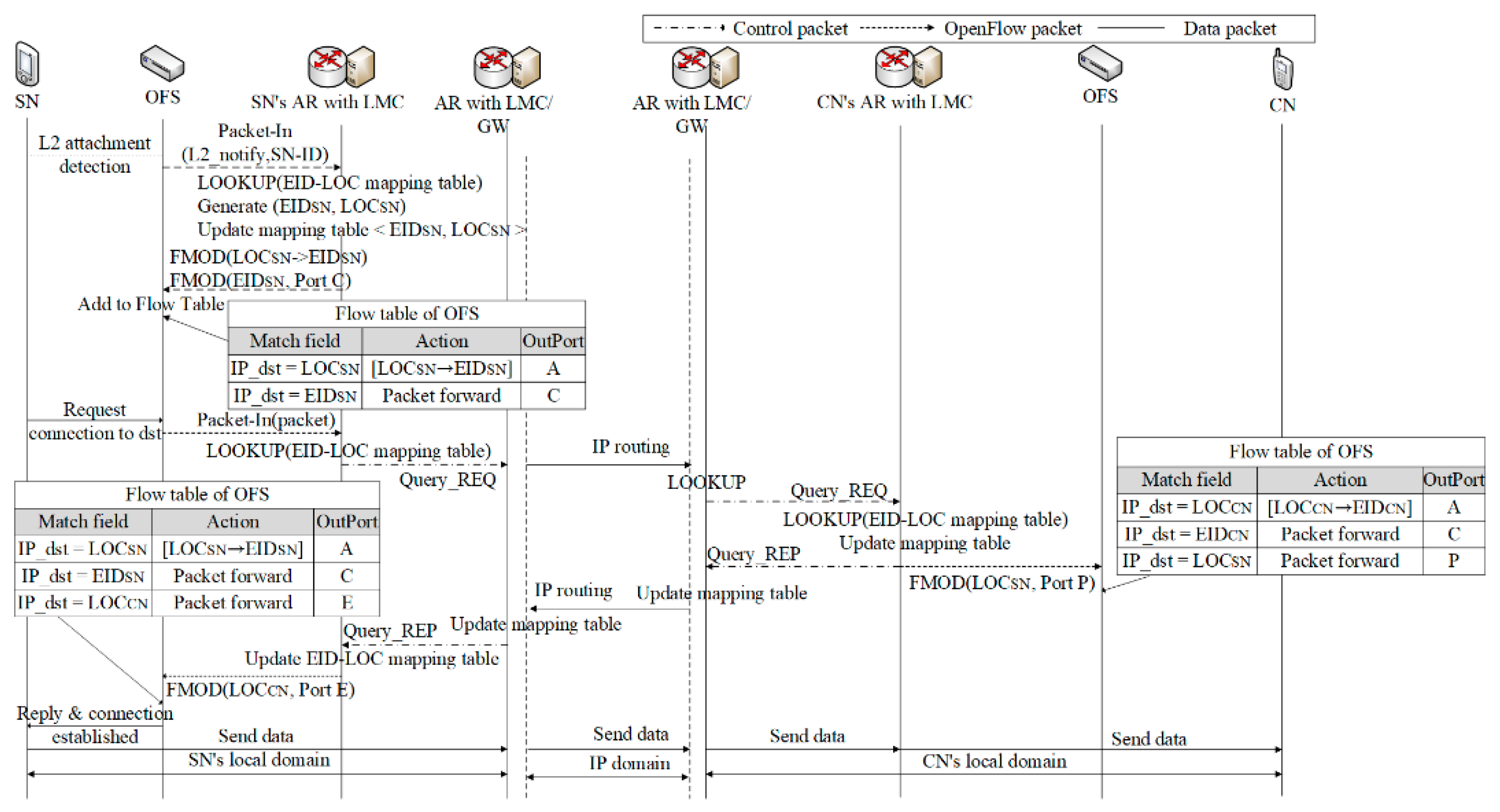
3.4.1. Registration and Packet Forwarding Process

The ARs of the proposed scheme are operated by an AR processing algorithm. The algorithm consists of three procedures according to the AR’s role, and the algorithms for ARs are illustrated in Algorithm 1.
If a new MN tries to connect to the network, it has to register itself to obtain necessary services. When the MN attaches to the network, the nearest OFS detects the attachment. If the OFS does not have any information about the MN in its flow table, it notifies the attachment of the MN to its AR. This AR becomes the s_AR of the MN, and it also detects the L2 attachment. From the L2 attachment, the s_AR can acquire the MN’s ID and then can generate the EID and the LOC of the MN. The s_AR first looks up the EID routing table to find a dedicated next hop port for the EID. After that, the s_AR sends a registration request to the h_AR of the MN with its EID or LOC address, and it also sends a command to add a flow table entry to its OFS. This flow table entry is used for the ingressive packets using LOC to exchange an LOC for the EID of the MN. As the ARs are able to know their neighbor ARs using neighbor a detection mechanism like that in [18], the paths between ARs are already pre-configured. Therefore, the s_AR can find the next hop port for the EID. Lines 2–15 of Algorithm 1 illustrates the procedure.
Algorithm 1. Registration and Packet forwarding
1: receive a packet pkt from the OFS
2:   if destination is MY ADDRESS (EID or LOC of this AR) then
3:     if pkt:type is L2 ATTACHMENT NOTIFY then
4:       save MN-ID from pkt; generate E I D M N using N A I M N ; generate L O C M N using M A C M N
5:       LOOKUP EIDRoutingTable for the next hop port(D)
6:       send EID REG REQ( E I D M N , L O C M N ) to h_AR( E I D M N )
7:       add ( E I D M N , L O C M N ) to BindingUpdateList; add flow table entry ( L O C M N E I D M N )
8:     else if pkt:type is EID registration reply then
9:       done
10:     end if
11:   else if pkt:dst is in MY EID address block then
12:     if pkt:type is EID registration request then
13:       add <EID,LOC> to BindingCache; add a flow table entry(pkt:EID → pkt:LOC)
14:       send EID registration reply to pkt’s src
15:     end if
16:   else if pkt:dst is not in MY EID address block then
17:     LOOKUP EID routing table(dst) for next hop port(D); add a flow table entry ( E I D M N , D); Packet-Out(pkt)
18:   else
19:     drop packet
20: end if
For the first received query request, the iOFSs do not have any entries related to the query. They send the query to their ARs for obtaining suitable flow table entries. After receiving the query, the n_AR checks whether the EID is included within its EID block. If not, the n_AR looks up its EID routing table for the next hop port. Then, it adds a flow table entry for the query to its OFSs, and the OFSs forward the query to the port toward to the MN’s AR according to the flow table.
When the query request arrives to the OFS of the MN’s AR, it forwards the query to its controller, the h_AR. The h_AR also checks the EID according to Algorithm 1, and then it adds the EID–LOC mapping information to its binding cache. The MN’s AR sends a command to its OFSs to add a flow table entry with the action that replaces the destination address from the EID to the LOC and that forwards the replaced packet to the IP domain. After sending the command to its OFS, it replies to the s_AR of the MN. The registration processes are terminated after the MN’s s_AR receives the reply.
For the packet forwarding, an MN may send a packet with EIDs as the source and destination address. If the OFS of the AR which the MN is attached to has no flow table entries for E I D C N , it forwards the MN’s packet to the AR. The AR looks up its EID routing table to handle the received packet. After finding the next hop port to forward the packet toward the destination, the AR sends a command to add a flow table entry to its OFSs according to Algorithm 1. Then, the packet is forwarded to the OFS of the h_AR via the n_ARs and their OFSs. The OFS of the CN’s AR already has the flow table entry for the destination EID via the registration process, the OFS of the CN’s AR performs the action in the flow table that replaces the E I D C N in the destination address field to L O C C N . After the field replacement, the OFS sends the packet to the output port of the IP domain for normal IP routing. The packet arrives at the OFS of the CN’s s_AR via the IP domain, and the field replacement occurs again from L O C C N to E I D C N at the OFS of the CN’s h_AR. After that, the OFS of the CN’s AR forwards the packet to its destination. The routes for the packet from the MN to the CN are established after the first packet arrives, and subsequent packets follow the configured routes. Figure 2 illustrates the registration and packet forwarding process.

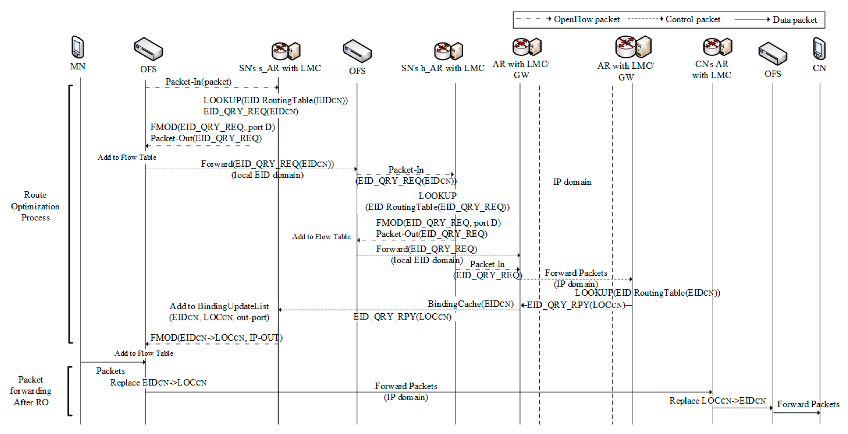
3.4.2. Route Optimization Process

When the packets are forwarded with the established routes, the packets are always passed to the OFSs of the CN’s AR through the routes which include several intermediate OFSs that are located in the MN’s AR and the CN’s h_AR. The routes established via the IP domain are optimized by IP routing, but all of the routes from the MN to the CN may not be. If the interconnected OFSs between the MN and the CN have the appropriate flow table entries for forwarding packets through the IP domain, it is clear that the entire route from the MN to the CN will be optimized.
During the packet forwarding process, the MN’s s_AR does not have information about the CN, so it sets a flow table entry to its OFSs and forwards the packet to the n_AR that is adjacent to the CN. At this stage, the MN’s s_AR also sends a query request to the CN’s AR by using its EID as the source address and the CN’s EID as the destination address to get the CN’s LOC. If the destination CN is in the local domain, similar to the registration process, then the n_ARs transmit the query request to the CN’s AR. After the CN’s AR receives the query request, it verifies the validity and sends a reply to the s_AR with the LOC. After the s_AR receives the reply, the AR is able to save the CN’s <EID, LOC> mapping information. It gives orders to the OFS that is connected to the CN for adding or modifying the flow table entries. The orders include an action set that converts the destination address field from the CN’s EID to the CN’s LOC and changes the out port of the packets.
If the CN’s EID does not exist on EID blocks in the local domain, then the CN is located in the other domain. The s_AR verifies the validity of the EID, and, if the EID is not invalid, it requests query to the other domain through the IP domain. In this case, the CN’s EID cannot be used for the destination address field within the SN’s local domain because the CN’s EID is only allowed to be used within the CN’s local domain. After receiving the reply, the LMC of the AR which has a role of the gateway (GW) updates its flow table entries, and it sends the reply to the s_AR. Then, the s_AR gives an order to its OFS to update its flow table entries.
When the route optimization (RO) process ends, the packets toward to the CN can be directly forwarded between the OFSs of the MN and the CN via the IP domain. Algorithm 2 describes the RO processes between the MN and the CN, and Figure 3 shows the packet forwarding after RO. In order to provide an optimized path between the MN and the CN, a route optimization algorithm for the AR was designed, as shown in Algorithm 2, and it should be inserted at the end of the AR in Algorithm 1.
Algorithm 2. Route Optimization
1: Require: the AR acts as s_AR
2:   if pkt:src is in BindingUpdateList then
3:     send EID query request to pkt:dst
4:   else if pkt:dst is MY EID ADDRESS(EID of s_AR) then
5:     if pkt:type is EID query reply then
6:       add a flow table entry (pkt:dst → pkt:loc)
7:     else
8:       drop packet
9:     end if
10:   else
11:     if pkt:dst is in MY EID address block then
12:       if pkt:type is EID registration request then
13:         add <EID,LOC> to BindingCache; add a flow table entry(pkt:EID → pkt:LOC)
14:         send EID registration reply to pkt’s src
15:     end if
16:   end if
17: Require: the AR acts as h_AR
18:   if pkt:dst is in MY EID ADDRESS BLOCK then
19:     if pkt:type is EID query request then
20:       lookup BindingCache(pkt:dst); send EID query reply with ( L O C M N ) to pkt.src
21:     else
22:       drop packet
23:     end if
24:   else
25:     if pkt:dst is not in MY EID address block then
26:       LOOKUP EID routing table(dst) for next hop port(D); add a flow table 27: entry ( E I D M N , D)
28:       Packet-Out(pkt)
29:     else
30:       drop packet
31:     end if
32:   end if

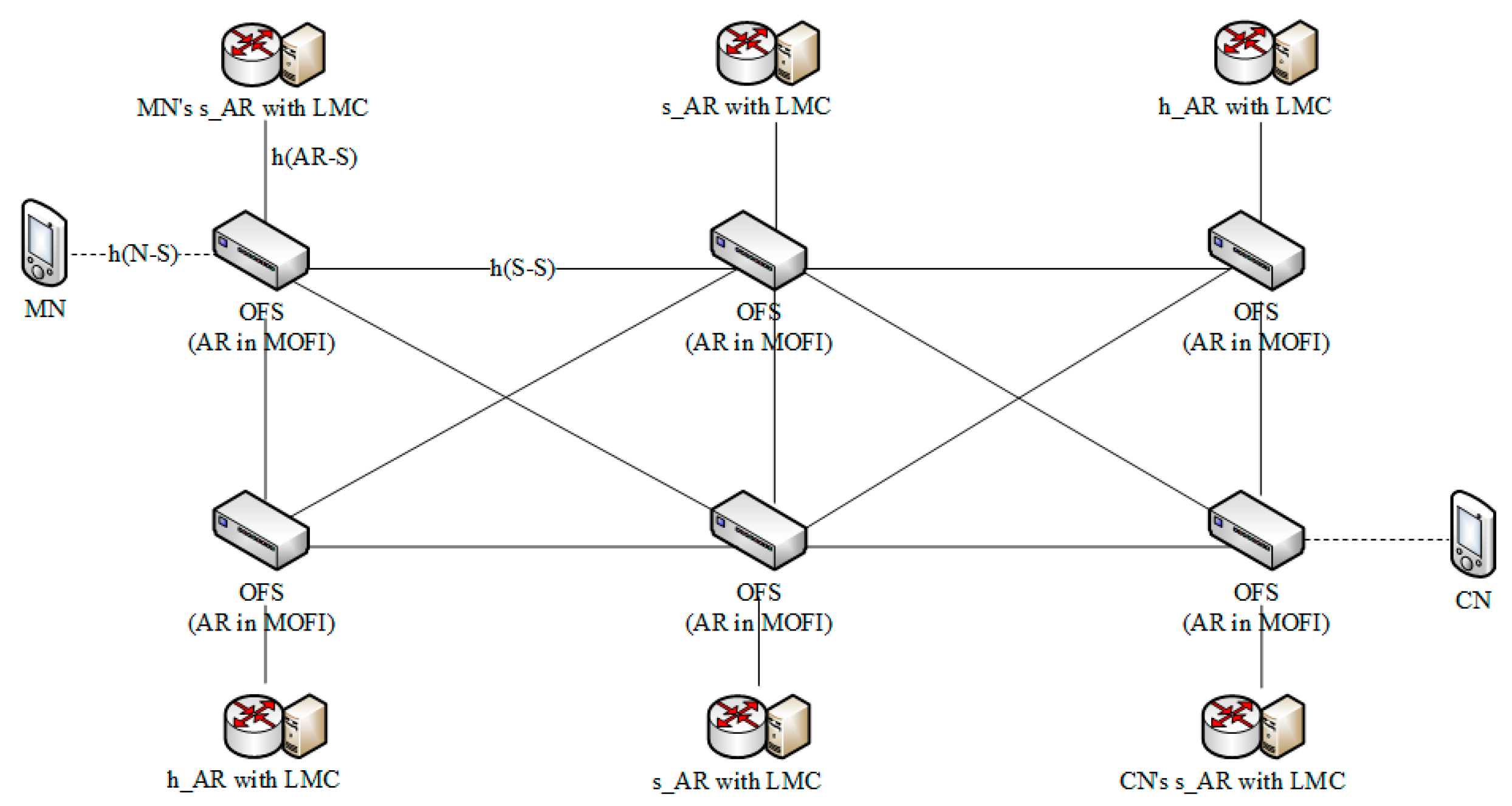
4. Cost Model Analysis

For calculating costs for signaling and packet forwarding, we configured the network topology, as shown in Figure 4, based on [28]. The network consists of six ARs and six OFSs with two MNs. Each OFS is connected to each other and each AR. The OFS has a wireless access point to connect to the mobile devices such as an MN or a CN.
For the comparison of the signaling and packet forwarding costs, MOFI was selected because it is similar to the proposed scheme. However, because MOFI and the proposed scheme require different entities, it was assumed that some functions of the network entities could be substituted according to the protocols. When the MN communicates with the CN in MOFI, each AR includes an LMC with a hash table and an HLR. Additionally, the EID–LOC mapping information is managed by the ARs in distributed manner, and they do not participate in packet forwarding. For more details of the operations such as the EID–LOC binding and data delivery, refer to [17].
In contrast, each AR in the proposed scheme is capable of including all the facilities of the OpenFlow switch. In Figure 4, h ( X Y ) indicates the average number of hops between X and Y, as follows:
  • h ( N S ) : The average number of hops between the node and the OFS
  • h ( A R S ) : The average number of hops between the AR and the OFS
  • h ( S S ) : The average number of hops between the OFSs
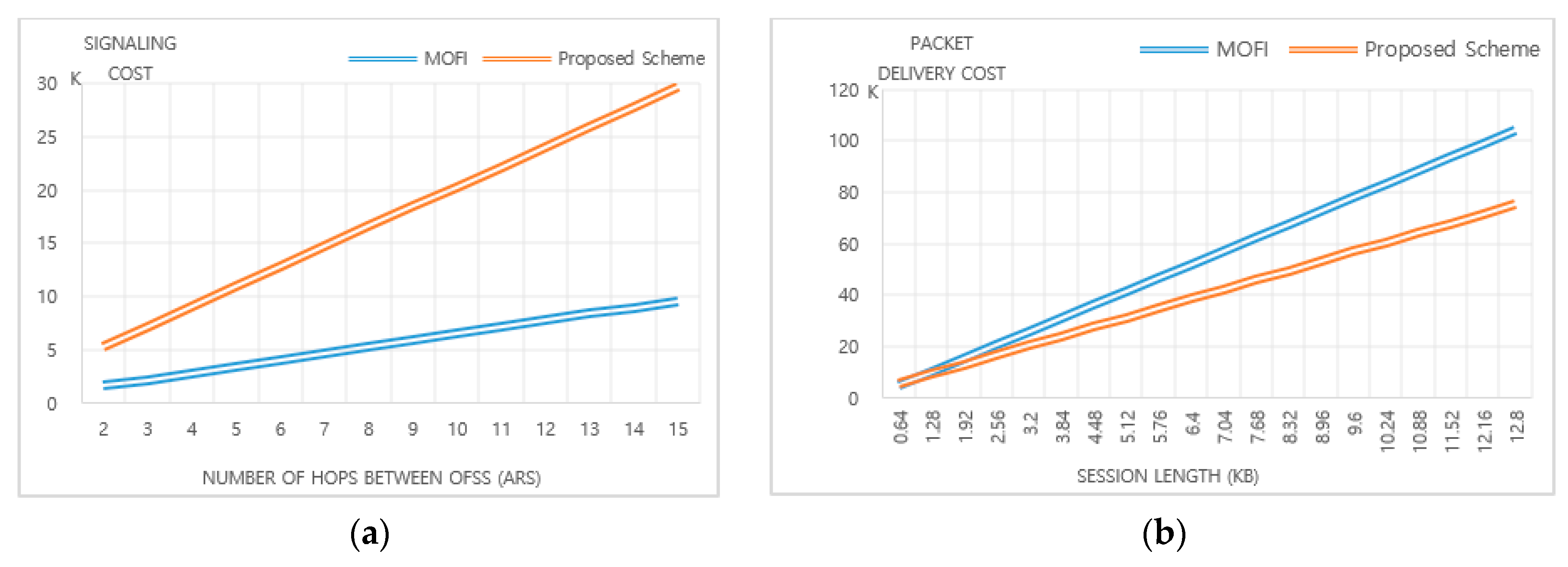
For the comparison between MOFI and the proposed scheme, we formulated the signaling and packet forwarding cost. The signaling cost ( C S ) and delivery costs ( C P D ) can be represented as the message sizes in bytes, and they can be calculated as the multiplication of the lengths of the path in the hop count via the route for the transmission. The total cost is calculated the sum of C S and C P D . For simplicity, we denote the cost of MOFI as C S M and the cost of the proposed scheme as C S N e w .

4.1. Signaling Cost

4.1.1. MOFI

In MOFI, the EID–LOC binding and LOC query procedures have to be preceded before forwarding the data packets. As such, signaling cost C S M can expressed by:
C S M = C B I M + C L Q M ,
where C B I M and C L Q M represent the cost of EID–LOC binding and the cost of LOC query in MOFI, respectively. After the L2 attachment, the MN sends a binding request (BR) message of the EID to the attached AR ( L M C ( A R M N ) ). Then, the L M C ( A R M N ) forwards the BR to the LMC ( L M C M N ), which maintains and manages the MN. After the processing of the BR, the L M C M N sends a binding acknowledgement (BA) message to the MN. It was assumed that the EID–LOC binding cost of an MN is the same as the cost of an CN, so the binding cost can be calculated as:
C B I M = 2 ( L B R + L B A ) ( h ( N S ) + h ( S S ) ) ,
where L B R and L B A represent the lengths of the BR and the BA, respectively. When the LMCAR−MN receives the first data packet from the MN to the CN, it starts the LOC query procedure to get the suitable LOC of the CN. Thus, the LOC query request (LQR) message is delivered to the L M C A R C N via the L M C C N . In case of the LOC query reply (LQP) message, it is delivered from L M C A R C N to L M C A R M N . Therefore, the cost of the LOC query is calculated as:
C L Q M = 2 h ( S S ) L L Q R + h ( S S ) L L Q A ,

4.1.2. Proposed Scheme

For communication between the MN and the CN, both nodes should be registered to their own h_ARs at first. After the L2 attachment, the MN’s s_AR sends a registration request (RR) to the h_AR, according to Algorithm 1. Additionally, the MN’s s_AR can send a query request for route optimization. It is also assumed that the average registration cost of the MN and the CN is the same. Thus, the signaling cost of the proposed scheme is calculated as:
C S N e w = 2 ( C R R Q N e w + C R O N e w ) ,
where C R R Q N e w and C R O N e w indicate the costs of registration and RO, respectively. Here, C R R Q N e w is calculated as the aggregate of the registration request cost C R R N e w and the registration reply cost C R P N e w . Thus, the C R R Q N e w is calculated as:
C R R Q N e w = C R R N e w + C R P N e w .
The C R R N e w includes the cost for delivering the RR message (DRR) and OpenFlow signaling cost (ORR). Thus, the C R R N e w is calculated as:
C R R N e w = C D R R N e w + C O R R N e w .
The RR message is forwarded from the s_AR to the h_AR of the MN, so C D R R N e w is expressed as:
C D R R N e w = h ( S S ) L R R ,
where L R R indicates the length of the RR message. The C O R R N e w is classified according to the role of the AR. Each AR’s OpenFlow signaling cost is expressed as C R R s _ A R , C R R h _ A R , and C R R n _ A R to process the RR message. Therefore, the total cost of OpenFlow for processing the RR message is calculated as:
C O R R N e w = C R R s _ A R + C R R h _ A R + C R R n _ A R .
The cost of sending the RR of each AR is calculated differently. In case of the s_AR, it creates flow table entries in its OFS by sending flow modification (FMOD) control messages with the “add” action. FMOD messages consist of two types: one for forwarding the RR message to the next hop and another for replacing the MN’s LOC into the EID. Therefore, the cost of the RR in the s_AR is calculated as:
C R R s _ A R = h ( h _ A R S ) ( 2 L F M O D + L R P O U T ) .
In Equation (9), L F M O D indicates the length of the FMOD message and L R P O U T represents the length of the packet-out (POUT) message containing the RR message.
In the case of the n_AR, it receives a packet-in (PIN) message from its OFS and responds with an FMOD to add a flow table entry to forward the RR message. In addition, the n_AR sends one more FMOD message to set the reverse path of the registration reply message (RP). Thus, we can calculate the cost of the RR at the n_AR as:
C R R n _ A R = ( h ( S S ) 1 ) ( L R P I N + 2 L F M O D + L R P O U T ) h ( A R S ) ,
where L R P I N indicates the length of a PIN including the RR message.
In case of the h_AR, it receives the PIN including the RR message from its OFS and sends FMOD messages to its OFS. The FMOD messages that are sent to the OFS include the actions for replacing the MN’s EID into the LOC and for forwarding the RP. Thus, we can calculate the cost of the RR at the h_AR as:
C R R h _ A R = h ( A R S ) ( L R P I N + 2 L F M O D ) .
By using these calculating processes, the cost of RP can be calculated as:
C R P N e w = C D R P N e w + C O R P N e w .
In Equation (12), C D R P N e w indicates the RP delivery cost and C O R P N e w represents the OpenFlow signaling cost. We can express the RP delivery cost as:
C D R P N e w = h ( S S ) L R P .
In Equation (13,) LRP indicates the RP message length. As the flow table entries for forwarding packets and replacing the LOC for the EID are already inserted in the OFSs, OpenFlow signaling cost is calculated as:
C O R P N e w = h ( A R S ) ( L R P P I N + L R P P O U T ) .
In Equation (14), L R P P I N and L R P P O U T indicate the length of the PIN and the POUT, respectively, including the RP. The cost for RO is also divided into the cost of query itself and the cost of the reply. The RO query (ROQ) cost is expressed as C R O Q N e w , and the RO reply (ROR) cost is expressed as C R O R N e w . Therefore, the cost for RO ( C R O N e w ) is calculated as:
C R O N e w = C R O Q N e w + C R O R N e w .
In Equation (15), the ROQ cost is consisted of the ROQ delivery cost (ROQD) and the OpenFlow signaling cost (ROQO), so the ROQ cost is expressed as:
C R O Q N e w = C R O Q D N e w + C R O Q O N e w .
The ROQ message is delivered from the MN’s s_AR to the CN’s h_AR, so the cost of the ROQ delivery is calculated as:
C R O Q D N e w = h ( S S ) L R O Q .
Flow tables for forwarding the ROQ are already created when the first packet is delivered. Therefore, the OpenFlow cost for forwarding the ROQ is the same as the sum of the PIN and the POUT containing the ROQ. We can express this cost for ROQO as:
C R O Q O N e w = h ( A R S ) ( L R Q P I N + L R Q P O U T ) .
In Equation (18), L R Q P I N and L R Q P O U T represent the length of the PIN and the POUT containing the ROQ, respectively. C R O R N e w is calculated as the sum of the ROR delivery cost ( C R O R D N e w ) and the OpenFlow signaling cost ( C R O R O N e w ). C R O R D N e w is calculated by multiplying h ( S S ) by L R O R . Thus, the ROR cost is expressed as:
C R O R N e w = h ( S S ) L R O R + C R O R O N e w .
Each AR has to configure flow table entries for forwarding the ROR message. The ROR message may be delivered from the CN’s h_AR to the MN’s s_AR. After the ROR arrives at the MN’s s_AR, the s_AR creates a flow table entry for replacing the CN’s EID to the LOC. Similar to the Equation (8), the OpenFlow signaling cost is calculated as:
C R O R O N e w = C R O R s _ A R + C R O R h _ A R + C R O R n _ A R ,
where C R O R s _ A R , C R O R h _ A R , and C R O R n _ A R indicate the OpenFlow signaling cost at the s_AR, the h_AR, and the n_AR, respectively. Each cost is calculated as:
C R O R s _ A R = h ( A R S ) L F M O D + L R O P O U T ,
C R O R n _ A R = h ( A R S ) ( h ( A R S ) 1 ) ( L R O P I N + L F M O D + L R O P O U T )   ,  
C R O R h _ A R = h ( A R S ) L R O P I N + L F M O D   .
In Equation (22), L R O P I N and L R O P O U T represent the length of the PIN and the POUT, respectively, including the ROR.

4.2. Packet Delivery Cost

The packet delivery cost is calculated with the number of packets and the length of packets. Because the packet delivery manner of MOFI is different from proposed scheme, the cost formula is also different. Under the subsection, the packet delivery cost of MOFI and the proposed scheme are depicted.

4.2.1. MOFI

In MOFI, the LOC query is already processed before delivering packets because of the characteristics of the query first data delivery (QFDD) [17]. Therefore, it is possible that packets are forwarded via a direct path between the MN and the CN. For the packet delivery, however, an additional header containing the LOC information is required. The A-LOC, which is used for forwarding packets within the L M C A R M N , is only routed from the MN to the L M C A R M N within the range of L M C A R M N . On the other hand, the B-LOC, which is included in the additional header, is used for the packet transmission from L M C A R M N to L M C A R C N . Both the inner header that uses the A-LOC and the outer header using the B-LOC have same length, the cost for packet delivery (PD) of MOFI is expressed as C P D M and calculated as:
C P D M = N ( p ) ( L D P + L L H ) ( 2 h ( N S ) + h ( S S ) )   ,
where N(p) and L D P represent the number of data packets and the length of data packets, respectively. L L H indicates the header length of the LOC information.

4.2.2. Proposed Scheme
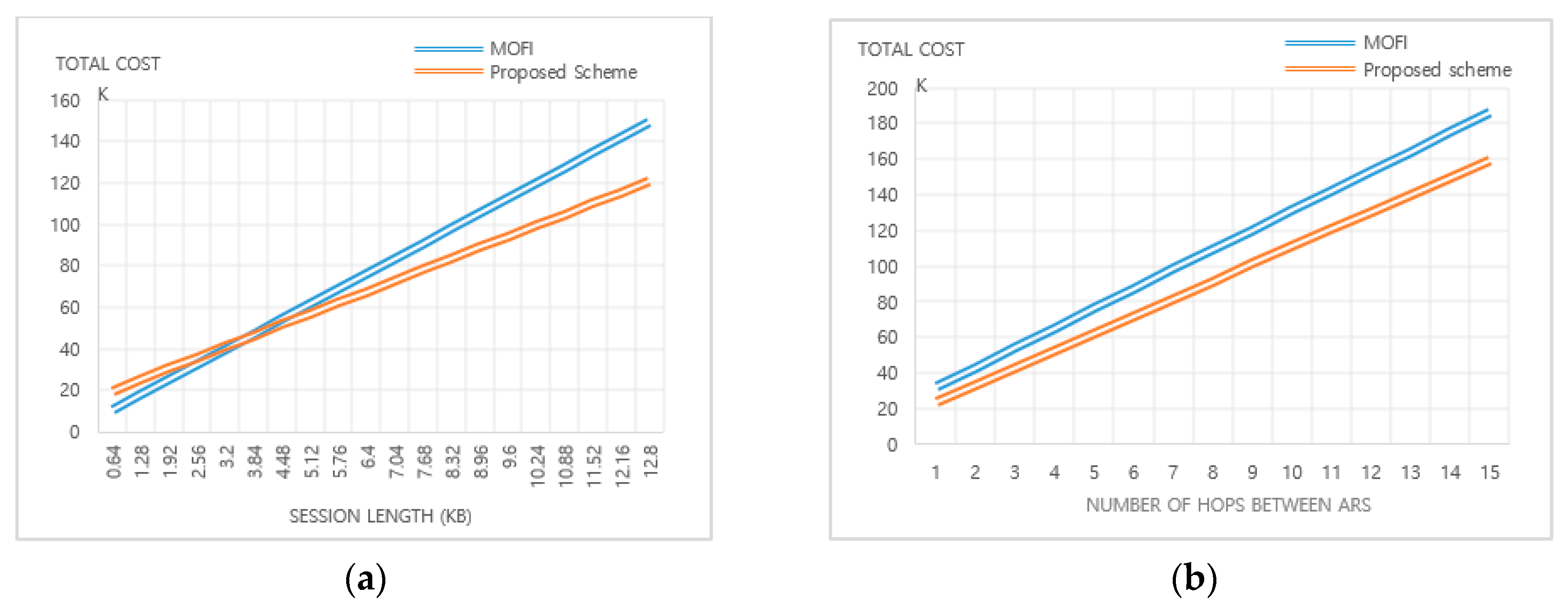
In the proposed scheme, the packet delivery cost is divided into the cost for forwarding data packets (FDP) and the cost for data delivery using OpenFlow (ODP). The first packet is forwarded through a non-optimal path from the OFSs to the ARs. After the RO process is completed, all packets should be routed through the optimal direct path. Therefore, the packet delivery cost C P D N e w is expressed as:
C P D N e w = C F D P N e w + C O D P N e w   ,
and the C F D P N e w is calculated as:
C F D P N e w = ( r n o N ( p ) L D P ( 2 h ( N S ) 2 h ( S S )   ) ) + ( ( 1 r n o ) N ( p ) L D P ( 2 h ( N S ) + h ( S S ) ) ) ,
where r n o indicates the ratio of packets delivered using the path that is not optimal. Flow table entries for the path from the MN to the CN’s OFS are created when the first packet is delivered. The cost generated by the CN’s AR does not occur because the packet arrived at the CN’s OFS is directly forwarded to the IP domain. Therefore, the cost for the ODP is only generated by the MN’s s_AR n_ARs. The total cost for the ODP contains the cost of the MN’s s_AR ( C s O D P N e w ) and the cost of the n_ARs ( C n O D P N e w ) and is expressed as:
C O D P N e w = C s O D P N e w + C n O D P N e w   ,
Though the first packet is delivered to the destination, flow table entries for the reverse path cannot be created until the reply message is sent back. Thus, C s O D P N e w and C n O D P N e w can be calculated as:
C s O D P N e w = h ( A R S ) ( L f P I N + L F M O D + L f P O U T ) and
C n O D P N e w = h ( A R S ) ( h ( S S ) 1 ) ( L f P I N + L F M O D + L f P O U T )   ,
respectively. In Equation (29), L f P I N and L f P O U T represent the length of the PIN and the POUT, respectively, including the first data packet.

5. Results

For the comparison between MOFI and the proposed scheme, we evaluated the costs of signaling and packet forwarding based on the cost model illustrated in Figure 4. The packet lengths used in the evaluation and some system parameters are shown in Table 1. All the packet lengths include the upper layers of the network layer. OpenFlow messages are delivered using Transmission Control Protocol (TCP), so 60 bytes of TCP ack size are involved in the packet lengths.
Figure 5 shows the comparison result for the signaling and packet forwarding cost of MOFI and the proposed scheme according to the change in the hop count and the session length. For example, the packet delivery cost in MOFI is calculated with Equation (24). The session length is calculated from the number of data processed per second. When the size of the data packet is large, the session length is also increased. Data that can be processed in one session were calculated by multiplying the packet length by the number of packets. Therefore, the packet delivery cost of the MOFI for the 10 packets can be calculated according to Equation (24) as follows:
C P D M = 10 ( L D P + L L H ) ( 2 hops   between   AR   and   node + hops   between   ARs ) = 5,200
In the case of the proposed scheme, the packet delivery cost for 10 packets can be calculated according to Equations (25) to (29) as follows:
C P D N e w = C F D P N e w + C O D P N e w = ( r n o 10 L D P ( 2 h o p s   b e t w e e n   A R   a n d   n o d e 2 h o p s   b e t w e e n   A R s   ) ) + ( ( 1 r n o ) 10 L D P ( 2 h o p s   b e t w e e n   A R   a n d   n o d e + h o p s   b e t w e e n   A R s ) ) + h o p s   b e t w e e n   A R   a n d   n o d e ( L f P I N + L F M O D + L f P O U T ) + h o p s   b e t w e e n   A R   a n d   n o d e ( h o p s   b e t w e e n   A R s 1 ) ( L f P I N + L F M O D + L f P O U T ) = 5,820
In this case, the packet delivery ratio that uses an suboptimal path ( r n o ) was set to 0.1. As a result, packet delivery costs according to 10, 20, 30, and 40 packets were calculated as 5200, 10400, 15600, and 20800 in MOFI, whereas, the costs in the proposed scheme were calculated as 5820, 9468, 13116, and 16764, respectively. Figure 5b shows the result that was calculated in MOFI and the proposed scheme. The signaling cost could be calculated through the same process, and the result is shown in Figure 5a.
As shown in Figure 5a, the signaling cost of the proposed scheme was higher than MOFI. In the proposed scheme, the OpenFlow messages in the EID domain are exchanged between ARs and OFSs, so it is reasonable that the proposed scheme always generates a higher cost than MOFI. In MOFI, the communication cost between the LMC and the AR does not appear because the LMC is located in the AR.
To compare packet delivery cost between MOFI and the proposed scheme, we established the number of hops between the OFSs (ARs) as 5. The session length was calculated by the multiplying packet length (LDP) by the number of packets N(p) and changed from 0.64 to 12.8 Kbytes. In contrast to the signaling cost, the proposed scheme showed a better result. Figure 5b describes the difference in terms of packet forwarding cost between MOFI and the proposed scheme.
As shown in Figure 5b, the gap of the linear graphs of MOFI and this scheme was greater as the increase of session length. Because MOFI performs packet encapsulation to transmit packets, it requires an additional header. In contrast, the proposed scheme only performs field replacement and forwards packets to the destination. Thus, it is believed that packet encapsulation leads to performance degradation in the case of packet transmission. If the nodes in the network are constrained and the number of nodes is huge, such as in the IoT environment, packet encapsulation can cause delays in data transmission and the amount of data that can be delivered within one segment is smaller.
The total cost was calculated with signaling cost and packet forwarding cost. The cost comparison is based on the cost model depicted in Figure 4. Figure 6a illustrates that MOFI showed a better performance than the proposed scheme under the session length of 3.84 Kbytes. However, the performance was changed to be better over the session length of 3.84 Kbytes. The signaling cost was not influenced by the session length, but the session length was the major factor in the increase of the packet delivery cost. As the session length increased, the extra overhead for encapsulation was increased.
As we mentioned earlier, the costs for signaling and packet forwarding were calculated based on the cost model that we suggested. Therefore, the results, except for those in Figure 6b, were calculated under equivalent conditions. In addition, we considered the case that the number of hops between the ARs were different, but the number of data packets were fixed. Figure 6b illustrates the comparison of the total cost between MOFI and the proposed scheme according to the variation of number of hops between the ARs with 100 packets. The proposed scheme showed a better performance than MOFI when the packets traversed more ARs.

6. Conclusions

In this paper, we proposed an SDN-based ID–LOC separation architecture for IoT networks. We concentrated on how to design and to provide scalability without any modification of the end nodes in the IoT network, and we tried to overcome the shortcomings that were caused by the binding of the IP addressing system. As a result, the paper showed the architecture and described the processes of registration, packet forwarding, and route optimization. The proposed scheme separates the underlying network into an EID domain and an IP domain to route the unrouteable EIDs. The hosts do not participate in the signaling procedure, and they do not consider any conversion procedure between the IDs and the LOCs. To analyze the signaling and packet forwarding costs, we configured a network topology and suggested a cost model for signaling and packet forwarding. Additionally, we calculated the signaling and packet forwarding costs with several parameters, and we compared our scheme with one of the existing solutions. From the analytical result, MOFI has a lower signaling cost than the proposed scheme, but it consumes more cost in packet delivery because it generates additional overhead through the use of tunneling. The total cost is influenced by the number of hops between the OFSs and session length. It was shown that the signaling overhead is negligible when the exponential increase of session size is considered.
The analysis model proposed in this paper is the result of analysis that considers only normal and general cases. In a real environment, there are various variables such as network errors and device failures, so many situations need to be considered. In the future, simulation analysis will be conducted on the proposed architecture through simulation tests to verify the analysis model. By constructing and applying a test environment modeling a real environment, it will be possible to improve the performance of the proposed technology and the analytical model.

Author Contributions

Formal analysis, C.H.L. and J.S.P.; funding acquisition, J.S.P.; methodology, C.H.L. and J.S.P.; project administration, J.S.P.; resources, C.H.L. and J.S.P.; writing—original draft, C.H.L.; writing—review and editing, C.H.L. and J.S.P. All authors have read and agreed to the published version of the manuscript.

Funding

This research was supported by the Basic Science Research Program through the National Research Foundation of Korea (NRF) funded by the Ministry of Education (NRF2017R1D1A1B03035833).

Conflicts of Interest

The authors declare no conflict of interest.

References

  1. Romero-Gázquez, J.L.; Bueno-Delgado, M. Software Architecture Solution Based on SDN for an Industrial IoT Scenario. Wirel. Commun. Mob. Comput. 2018, 2018, 2946575. [Google Scholar] [CrossRef]
  2. Khusanbek, G.; Tai-Myoung, C. Comprehensive Survey on Internet of Things, Architecture, Security Aspects, Applications, Related Techologies, Economic Perspective, and Future Directions. J. Inf. Process. Syst. 2019, 15, 797–819. [Google Scholar]
  3. Park, J.H.; Salim, M.M.; Jo, J.H.; Sicato, J.C.S.; Rathore, S.; Park, J.H. CIoT-Net: A scalable cognitive IoT based smart city network architecture. Hum.-Cent. Comput. Inf. Sci. 2019, 9, 29. [Google Scholar] [CrossRef]
  4. Mohammadi, V.; Rahmani, A.M.; Darwesh, A.M.; Sahafi, A. Trust-based recommendation systems in Internet of Things: A systematic literature review. Hum.-Cent. Comput. Inf. Sci. 2019, 9, 21. [Google Scholar] [CrossRef]
  5. Moskowitz, R.; Nikander, P.; Jokela, P. Host Identity Protocol: Internet Engineering Task Force (IETF) network working group, RFC5201. In Technical Report; IETF: Fremont, CA, USA, 2008. [Google Scholar]
  6. Nordmark, E.; Bagnulo, M. Shim6: Level 3 Multihoming Shim Protocol for IPv6, RFC5533. In Technical Report; IETF: Fremont, CA, USA, 2009. [Google Scholar]
  7. Atkinson, R.J.; Bhatti, S.N. Identifier-Locator Network Protocol (ILNP) Architectural Description, RFC6740. In Technical Report; IETF: Fremont, CA, USA, 2012. [Google Scholar]
  8. Farinacci, D.; Fuller, V.; Meyer, D.; Lewis, D. The Locator/ID Separation Protocol (LISP), RFC6830. In Technical Report; IETF: Fremont, CA, USA, 2013. [Google Scholar]
  9. Gohar, M.; Koh, S.J. Network-based Distributed Mobility Control in Localized Mobile LISP Networks. Commun. Lett. 2012, 16, 104–107. [Google Scholar] [CrossRef]
  10. Menth, M.; Klein, D.; Hartmann, M. Improvements to LISP Mobile Node. In Proceedings of the 22nd International Teletraffic Congress (ITC 22), Amsterdam, The Netherlands, 7–9 September 2010. [Google Scholar]
  11. Ratnasamy, S.; Francis, P.; Handley, M.; Karp, R.; Shenker, S. A scalable content-addressable network. ACM SIGCOMM Comput. Commun. Rev. 2001, 31, 161–172. [Google Scholar] [CrossRef]
  12. SDN Overview. Available online: http://www.opennetworking.org (accessed on 10 December 2019).
  13. ONF White Paper. Software-Defined Networking: The New Norm for Networks. Open Networking Foundation. Available online: https://www.opennetworking.org/images/stories/downloads/sdn-resources/white-papers/wp-sdn-newnorm.pdf (accessed on 10 December 2019).
  14. Available online: https://www.cisco.com (accessed on 10 December 2019).
  15. Available online: https://www.spirent.com (accessed on 10 December 2019).
  16. Kang, H.W.; Kim, J.I.; Koh, S.J. DHT-based Identifier-Locator Mapping Management for Mobile Oriented Future Internet. In Proceedings of the 18th Asia-Pacific Conference on Communications (APCC), Jeju Island, Korea, 15–17 October 2012; pp. 786–791. [Google Scholar]
  17. Kim, J.I.; Jung, H.; Koh, S.J. Mobile Oriented Future Internet (MOFI): Architectural Design and Implementations. ETRI J. 2013, 35, 666–676. [Google Scholar] [CrossRef]
  18. Luo, H.; Qin, Y.; Zhang, H. A DHT-Based Identifier-to-Locator Mapping Approach for a Scalable Internet. IEEE Trans. Parallel Distrib. Syst. 2009, 20, 1790–1802. [Google Scholar]
  19. OpenFlow Switch Specification, Version 1.5.1; Open Networking Foundation. Available online: https://www.opennetworking.org/wp-content/uploads/2014/10/openflow-switch-v1.5.1.pdf (accessed on 1 October 2018).
  20. Ha, N.; Kim, N. Efficient Flow Table Management Scheme in SDN-Based Cloud Computing Networks. J. Inf. Process. Syst. 2018, 14, 228–238. [Google Scholar]
  21. Montenegro, G.; Kushalnagar, N.; Hui, J.; Culler, D. Transmission of IPv6 Packets over IEEE 802.15.4 Networks. Internet Propos. Stand. RFC 2007, 4944, 130. [Google Scholar]
  22. Baddeley, M.; Nejabati, R.; Oikonomou, G.; Sooriyabandara, M.; Simeonidou, D. Evolving SDN for Low-Power IoT Networks. In Proceedings of the 2018 4th IEEE Conference on Network Softwarization and Workshops (NetSoft), Ontreal, QC, Canada, 25–29 June 2018. [Google Scholar]
  23. Nikander, P.; Laganier, J.; Dupont, F. An IPv6 Prefix for Overlay Routable Cryptographic Hash Identifiers (ORCHID); RFC4843; IETF: Fremont, CA, USA, 2007. [Google Scholar]
  24. Deering, S.; Hinden, R. Internet Protocol; Version 6(IPv6), RFC2460; IETF: Fremont, CA, USA, 1998. [Google Scholar]
  25. Thomson, S.; Narten, T.; Jinmei, T. IPv6 Stateless Address Autoconfiguration; RFC4862; IETF: Fremont, CA, USA, 2007. [Google Scholar]
  26. Rhim, H.; Tamine, K.; Abassi, R.; Sauveron, D.; Guemara, S. A multi-hop graph-based approach for an energy-efficient routing Protocol in wireless sensor networks. Hum.-Cent. Comput. Inf. Sci. 2018, 8, 1–21. [Google Scholar] [CrossRef]
  27. Jeong-Joon, K. Routing Techniques for Data Aggregation in Sensor Networks. J. Inf. Process. Syst. 2018, 14, 396–417. [Google Scholar]
  28. Jong-Hyouk, L.; Tai-Myoung, C.; Sri, G. A Comparative Signaling Cost Analysis of Hierarchical Mobile IPv6 and Proxy Mobile IPv6. In In Proceedings of the IEEE 19th International Symposium, Personal, Indoor and Mobile Radio Communications, Cannes, France, 15–18 September 2008; pp. 1–6. [Google Scholar]
Figure 1. System architecture of the proposed scheme.
Applsci 10 02144 g001
Figure 2. Registration and packet forwarding processes.
Applsci 10 02144 g002
Figure 3. Packet forwarding after route optimization.
Applsci 10 02144 g003
Figure 4. Topology for analyzing the cost model.
Applsci 10 02144 g004
Figure 5. Comparison between Mobile Oriented Future Internet (MOFI) vs. proposed scheme: (a) signaling cost comparison; (b) packet forwarding cost comparison.
Applsci 10 02144 g005
Figure 6. Total cost comparison between MOFI and the. proposed scheme: (a) fixed number of hops between ARs (5); (b) fixed number of data packets (100).
Applsci 10 02144 g006
Table 1. Parameters and packet size.
NotationSize (bytes)NotationSize (bytes)NotationSize (bytes)
L B R 88 L R P O U T 246 L R O R 88
L L Q R 88 L R P P O U T 246 L f P O U T 334
L R R 88 L R O P O U T 246 L L H 40
L R P 88 L R Q P O U T 246 L D P 64

