Article

A Soft, Biocompatible Magnetic Field Enabled Wireless Surgical Lighting Patty for Neurosurgery

1
Department of Electrical and Computer Engineering, Texas A&M University, College Station, TX 77843, USA
2
Department of Neurosurgery, Barrow Neurological Institute, St. Joseph’s Hospital and Medical Center, Phoenix, AZ 85013, USA
3
Center for Remote Health Sciences and Technologies, Texas A&M University, College Station, TX 77843, USA
*
Author to whom correspondence should be addressed.
Appl. Sci. 2020, 10(6), 2001; https://doi.org/10.3390/app10062001
Submission received: 23 January 2020 / Revised: 28 February 2020 / Accepted: 12 March 2020 / Published: 15 March 2020
(This article belongs to the Special Issue Advances in Bioelectronics)

Abstract

:
General surgical procedures are subject to low-light conditions or a narrow angle of view, and such limitations in light limit visibility and complicate the given surgical procedure. Conventional lighted surgical tools rely on an external light source, which may be oriented into a cavity or mounted on a surgical instrument such as retractor, endoscopes, or suction tubes. However, such conventional lighted instruments do not provide adequate lighting during various surgical procedures. Here, we present a soft, miniaturized magnetic-enabled wireless surgical lighting patty. Specifically, the proposed surgical lighting patty that can be temporarily implanted into a cavity or surgical corridor provides lighting to the surgical subject and manages fluids in a surgical field. The surgical lighting patty is a multilayer patty, two outer layers of the lighted surgical patty and the center lighted layer. A reed switch in the central layer can activate the power supply in response to a magnet to emit the light from the light source. The result allows a dramatically simplified wireless operation. Moreover, it can provide various wavelengths of light to a surgical field for purposes such as illuminating the surgeon’s field of vision, exciting dyes, and sterilizing surgical fields.

1. Introduction

The majority of modern surgical lighting illuminates from an external source, a dissecting microscope, into a cavity or is mounted on a surgical instrument, such as retractors, endoscopes, orthoscopic tools, and suction tubes [1,2,3,4,5,6]. However, such conventional implements and instruments are unable to provide sufficient lighting during various surgical procedures. For example, endoscopes could deliver light at the depth of a surgical field but not an extreme surgical cavity or corridor. It also offers a relatively narrow angle of view and is likely to limit the surgeon’s visual field [7]. Similarly, bipolar forceps or suction devices with light sources attached at the tip could also provide light for only short periods of time, in particular, when they are applied to a surgical field [8]. Low-light conditions during aneurysm surgery render deep surgical approaches far more dangerous [8,9]. It leads to limited visualization and a substantially increased risk of injury. As another example, various neurological procedures require deep dissection; however, the only light source consists of a microscope light oriented outside the patient [10,11]. Such limitation in light restricts visibility and, in some cases, complicates the given procedure. There is an unmet need to develop a surgical tool that can provide enough light at the depth of a surgical field for a considerable amount of time during surgery.
Neurosurgical patties (referred to as cottonoids or neurosurgical sponges) are widely used in neurosurgery, and they can manage biofluids and protect neural tissues from damaged ones in surgical fields [12]. Here, we present a versatile illuminated surgical patty that can compensate for deep, dark dissection surgical fields and simultaneously manage fluids in the field. Electronic components, including light emitting diodes, are mounted on a flexible polyimide substrate, and the device can make intimate contact with a surgical field [13,14,15,16,17]. Key aspects are multimodalities, delivery of light at the depth of a surgical field, and management of biofluids at the field. The proposed surgical lighting patty can provide miniaturized diffuse lighting to a surgical corridor for an improved surgical field of vision. Moreover, the surgical lighting patty can be used as a barrier for the management of fluids in a surgical cavity or corridor while providing enough light to the surgical field. For example, in neurosurgery, surgical patties are often used to line surgical cavities to protect normal, healthy nervous system tissues in a non-absorptive fashion during complicated surgical dissections.
The surgical lighting patty is comprised of three layers. Two outer layers, surgical sponges, sandwich together a central lighting layer. The central lighting layer includes an electronic circuit with light-emitting diodes (LEDs) and a reed switch embedded in it. Semiconductor components and a reed switch are connected by copper interconnections on a thin polyimide substrate, and a soft polymer, such as Polydimethylsiloxane (PDMS), encapsulates the central lighting layer. The light-emitting element in the layer defines a light source oriented along a substrate, and a reed switch engages in power control so that it activates or deactivates the power supply or a set of batteries in response to a magnet to emit the light from the light source. This results in a biocompatible, wireless operation. Through this study, we advance the flexible electronics technology for successful integration of miniaturized, low power LEDs into a surgical patty, which yields a novel, versatile wireless platform for use in neurosurgery.

2. Materials and Methods

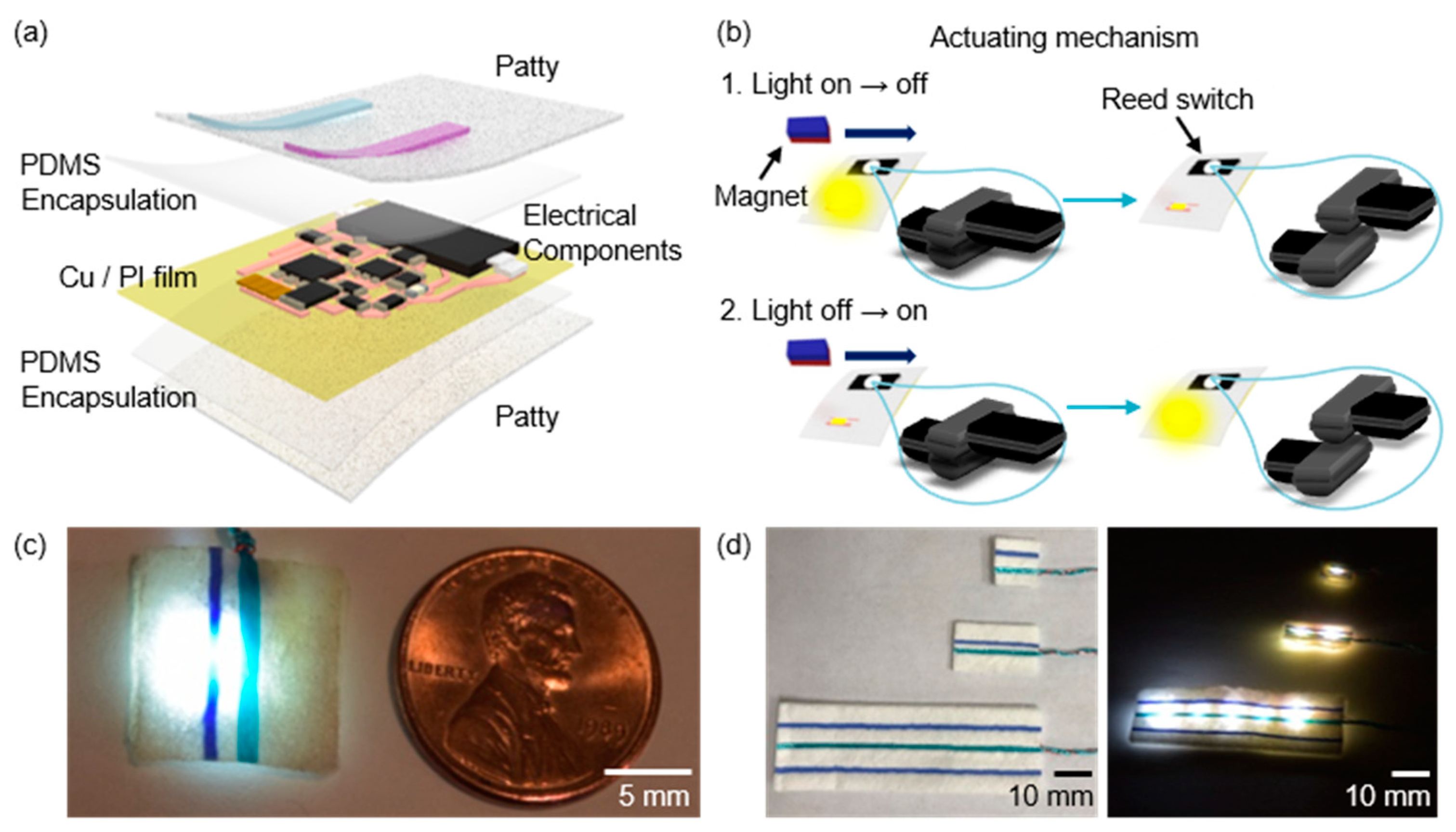
2.1. Fabrication for Surgical Lighting Patty

The process began with a copper (Cu, thickness: 18 µm)/polyimide (PI, thickness: 12 µm) bilayer film (AC181200R, DuPont™ Pyralux®, Wilmington, DE, US) on a glass slide (2” × 3”). Next, we deposited photoresist (AZ® 1518, AZ Electronic Materials, Somerville, NJ, US; spin-coating at 3000 r.p.m. for 30 s; baking on a hot plate at 100 °C for 4 min) on top of a bilayer film. The UV photo-lithography enabled us to expose the light (UV intensity for 265 mJ/cm2) to form patterns on the prepared film with a patterned mask. The solvent development (AZ® Developer 1:1, AZ Electronic Materials, Somerville, NJ, US; for 30 s) and wet etching (copper etchant, Alfa Aesar™, Tewksbury, MA, US; for 3 min) procedure define patterns, including copper traces and contact pads, on a flexible substrate. Next, we mounted components, including light emitting diodes (LED), which were being used for the light source (emitting color: white, material: InGaN, viewing angle: 140°, and light intensity: 640 Lux (with sponge), 1420 Lux (without sponge) of the proposed patty, transistors, a reed switch, resistors, and capacitors on the patterns by soldering. Biocompatible polymers, PDMS (SylgardTM 184 silicone elastomer kit, Dow®, Midland, MI, US, thickness: 50–100 µm), encapsulated the central lighting layer by a simple coating process and were cured at a vacuum oven at 80 °C for 1 h. The top and bottom surgical sponge then sandwiched together the encapsulated layer. This resulted in a thin (1 mm thickness), flexible surgical lighting patty. For powering the device, thin enameled wires twisted with retrieval strings connected batteries to the light-emitting element. Collectively, our devices could be fabricated with 8 hours of effort in standard laboratory facilities using low cost commercially available components. The following Table 1 summarizes the steps required for tests and fabrication of the surgical lighting patty, and detailed information on the layout and components are found in Figure S1 and Video S1, S2.

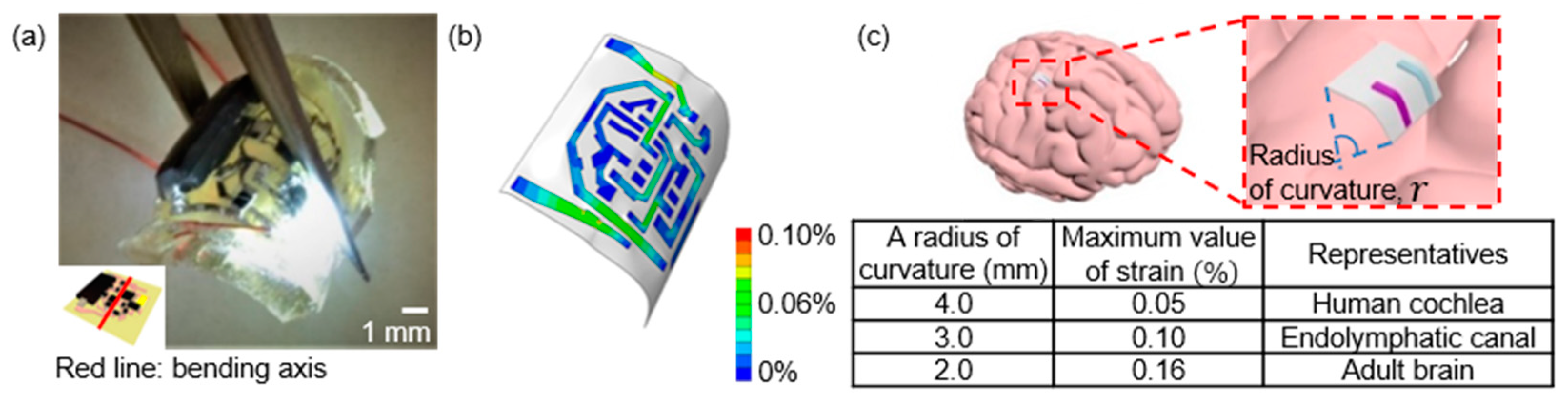
2.2. Finite Element Analysis

We used a commercial finite element analysis tool, Abaqus/CAE 2018 (Dassault Systemes, Vélizy-Villacoublay, France), to investigate strain effects on the surgical lighting device. Parameters used for simulations are as follows; thickness (PDMS/Cu/Polyimide/PDMS: 50/18/12/50 (µm)) and elastic properties (Young’s modulus (MPa)/ Poisson’s ratio: 1/0.49 for PDMS; 119000/0.34 for Cu; 2500/0.34 for polyimide). Electrical components, such as LEDs, reed switch, N-type metal-oxide-semiconductor (NMOS), P-type metal-oxide-semiconductor (PMOS), capacitor, and resistors, are modeled as rigid objects. The top, middle, and bottom layers are modeled as a solid hexahedron element (C3D8R), composite shell element (S4R), and solid hexahedron element (C3D8R), respectively.

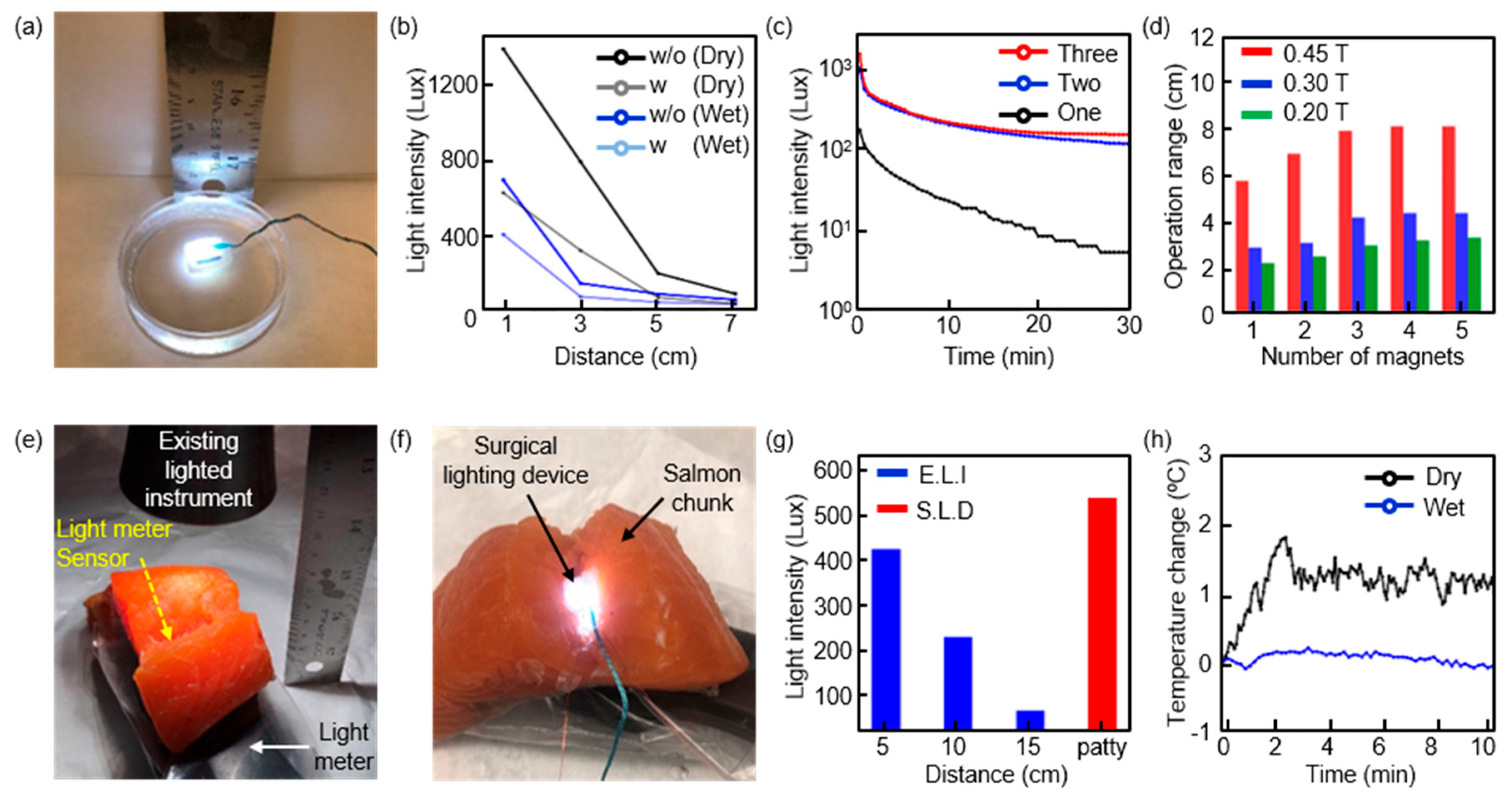
2.3. Measurements of Surgical Lighting Devices

We measured light intensity of wireless surgical lighting devices using a light meter (LT300, Extech, Nashua, NH, US) at various conditions. To determine how long the device can maintain functionality in biofluidic environments, we monitored light intensity as a function of time where the devices are immersed in phosphate-buffered saline (PBS, Sigma-Aldrich, St. Louis, MO, US) solution. For operational dynamic ranges of the surgical lighting device, we used different combinations of magnets to determine their switching characteristics. In addition, the salmon chunk was cut to create an environment similar to the actual operation situation, and the light intensity of the proposed device was compared with the conventional light emitting devices (SUN-LITE I, Scientific instruments Inc, Schaumburg, IL, US) in this condition.

3. Results

The schematic illustration shows the anatomy of the surgical lighting device (Figure 1a). The surgical lighting patty consists of three layers: the central lighting layer and top/bottom surgical sponge. The device includes an actuating mechanism along the substrate or proximate to the power supply and electrically coupled to the power supply and/or light source. Here, a reed switch is configured to activate and/or deactivate power from the power supply when a magnetic source is positioned proximate to the actuating mechanism (Figure 1b). A reed switch makes physical contact in response to a magnetic field. The result allows a dramatically simplified wireless operation. Figure 1c,d provides visual evidence of the wireless operation enabled by a remotely located magnet. The wireless surgical lighting device can be extended to designs that incorporate more light sources in many sizes of a surgical patty (Figure 1d; right).
A circuit diagram of the surgical lighting patty appears in Figure 2a,b highlights a signal flow from a power supply to light sources and captures the transient response. The circuit consists of three parts: a set of batteries, a toggle logic circuit, and lighting-emitting elements. A set of batteries powers a toggle logic circuit, the light emitting elements, and the control logic activates or deactivates LEDs. Here, an RC time constant, a measure of the ability of a circuit to respond to fast input signals and defined by the product of resistance (R4) and capacitance (C1), determines a transient response of the circuit [18,19]. As we increase R4 and/or C1, the pulse width required for switching increases (Figure 2c). Plots of voltages at nodes of V1, V2, and V3 (S1) as a function of time provide details on transient responses (Figure 2d). Assuming that LEDs turn off, a set of batteries charges a capacitor, C1, through R1 and R2 resistors (Figure 2e). When a reed switch, denoted by S1, closes in response to a magnet, electrical charges stored at C1 release through a resistor, R4. This induces a voltage drop across R4, and subsequently turns on a transistor, NMOS2, (Figure 2f). Then, NMOS2 provides a signaling pathway for the LEDs, and the LEDs light up (Figure 2g). Consequently, an activation of the NMOS2 transistor enables PMOS and NMOS1 transistors, and this prevents charging through C1 (Figure 2h). Procedures for deactivation are reversible (Figure 2i). A reed switch causes the gate voltage of NMOS2 to move away from the threshold voltage when we place a magnet in an attempt to deactivate the device (Figure 2j). This results in deactivation of NMOS2 and no currents across LEDs flow, as shown in Figure 2k. Consequently, the signaling pathways of this route are changed toward C1, and a set of batteries charges C1 (Figure 2l). When a magnet is positioned proximate to a reed switch again, it activates LEDs. Video S1 provides visual evidence of the robustness of the operation.
The topography of the surgical field, such as specific cavities or corridors, is uneven, narrow, or difficult in which to operate. A highly deformable lighting surgical device can fit into difficult, narrow, or uneven surgical fields (Figure 3a). It provides the types of lighting required for the procedure while preventing a physical obstruction to the surgical field. Such surgical lighting devices can be given a specific conformation prior to implantation into the surgical area to provide certain functions during surgery. These functions involve the support of tissue, expanding the surgical field, and projection of light in a specific direction. Figure 3a shows the device bent to a radius of curvature R = 3 mm. The finite element analysis (FEA) revealed that for R = 3 mm, the maximum effective strain in copper traces is 0.1%, which is lower than its fracture strain (~5%) (Figure 3b) [14]. This suggests that surgical lighting devices can be applied to other organs systems, such as the human cochlea, men’s endolymphatic canal, and adult brain (Figure 3c) [20,21,22]. Collectively, the deformability, memory, and size of LEDs make the device useful for narrow surgical corridors of corridors that naturally limit light, like the surgical abdomen viewed through a laparoscope.
A set of batteries external to the surgical lighting device powers an electronic circuit including a control logic and LEDs. In this manner, the power supply can also be positioned outside of the surgical field during deployment of the lighting device. The encapsulated central lighting layer protects an electronic circuit, including a reed switch and logic circuits, from fluids and therefore ensures robust operation in a surgical field while managing fluids in the field (Figure 4a) (Video S2). The light intensity of a surgical lighting device is monitored when immersed in a fluid as a function of distance between a magnet and a device (Figure 4b) and time (Figure 4c). Unstable device operation or activation/deactivation by accident is associated with environmental noises, and management of such issues is critical for robust operation. Magnetic field intensity is inversely proportional to square distance, and its strength significantly reduces as it moves away from a source [23,24]. This ensures robust operation in a manner that offers nearly complete insensitivity to surroundings provided limiting access of a magnet or environmental noise sources that may trigger the device at most 8 cm away from the device (Figure 4d). Figure 4e,f shows measurement setups. Here, we place a light sensor under a chunk of salmon and measure light intensity. For measurements of existing light instruments, we measured light intensity as a function of distance, ranging from 5 to 15 cm, between the surface of salmon and the lighting device. Since a surgeon’s field of vision must be secured, we did not measure below 5 cm. Measurement results revealed that the wireless surgical lighting patty provides higher light intensity than existing light instruments do (Figure 4g). Understanding thermal characteristics of the lighting device is important since it may cause tissue damage by heating [25]. We assessed the thermal characteristics of the surgical lighting patty using an embedded temperature sensor. No detectable increase in temperatures during operation was observed (Figure 4h). This suggests that the wireless surgical patty does not cause tissue damage associated with heating.

4. Discussion

Battery or near-field powered microcontroller chips could enable similar levels of functionalities, remote control of light delivery, or activation/deactivation of light sources. Their power requirement for wireless operation ranges from a few mA to tens of mA. It could be delivered by near-field couplings between a transmission coil and a receiver coil if the dimensions of a receiver coil are realistic, for example, 3 by 3 cm. Otherwise, power transmission efficiency significantly drops as the receiver coil is scaled down below 1 by 1 cm, similar to the minimum size of a surgical lighting patty [26]. Moreover, a battery (capacity of 10 mAh) powered microcontroller chip could last at most 1 h. On the other hand, an actuating mechanism enabled by a customized circuit, including a reed switch, allows for low power wireless operation (a few µA) in a manner that is impossible with near-field powered microcontroller chips (a few mA) [27]. Battery with the same capacity, 10 mAh, is enough to operate the customized circuit, up to 10 h. Existing lighted instruments, such as an endoscope, suction device, or bipolar forceps, with light sources attached at the tip could also achieve a similar level of functions. However, such lighted instruments can provide light with a narrow angle of view or only when they are applied to a surgical field. Their form factors also make them less ideal for applications in surgery that require deep dissection, such as brain surgery or lung cancer [28]. For example, aneurysm surgery requires deep dissection where access to targeted tissues or regions is allowed only through a narrow opening. Existing lighted instruments could access and deliver light through wide openings; however, we cannot avoid damage of nearby cells associated with removals of surrounding tissues. Similarly, surgery processes for a brain tumor or lung cancer could be facilitated by our surgical lighting patty. Photodynamic therapy (PDT) is a treatment that uses a photosensitizer and a particular type of light. When photosensitizers are exposed to a specific wavelength of light, they produce oxygen radicals that kill nearby cells; in particular, tumor cells [29]. Here, continuous, uniform light delivery is critical for achieving high cure rates [30]. Access to tumor cells in the brain or organ systems is difficult, while skin tumors allow easy access to light. Our thin, miniaturized flexible surgical lighting patty can represent an attractive alternative. Lastly, alternative approaches described above except for suction devices cannot manage biofluids in a surgical field. Collectively, a hundred-folds reduction in power consumption, miniaturized dimensions, and multimodalities represent essential features of the wireless surgical lighting patty.
The power supply can take a variety of forms. In some embodiments, the power supply can be integrated within or positioned along the light-emitting element. Alternatively, the power supply can be oriented external to the light-emitting element or be positioned outside of the surgical area during deployment of the light-emitting element. The light source also can be powered by inductive coupling from a base station. The surgical lighting patty can incorporate an over-sized retrieval string that serves the purpose of providing the operating surgeon a mechanism to pull a surgical lighting patty from the surgical field. Additionally, the retrieval string could be modified in manners that serve as an insulated electrical conduit to supply the power to the lighted elements in the surgical patty upon contact or at all times. The lights arranged in specific formations or arrays could be another implementation. Each array may have a specific function or advantage. Some embodiments include lights or LEDs arranged in a columnar, staggered, multi-row, triangular, circular fashion, or alternating wavelengths. They can provide diffuse ambient light to a surgical field or emit light from only one of two faces of the lighted surgical patty, depending on their configuration. It is advantageous for various types of surgical settings.
In another implementation, various types of LEDs with different wavelengths can be used to output a wide range of wavelengths. Such configuration allows for illuminating dyes that are often inserted into the body, including vasculature, neurological tissue, and ducts to better visualize cancerous tissue and arterial vasculature. When a light at a certain wavelength from the patty activates molecules contained in the dyes, the molecules emit fluorescence light that is detectable either by sight or other detection equipment. This permits surgeons to detect movement of fluids, uptake of molecules, blockage, breakages, etc. Similarly, blue spectrum lighting can be utilized to identify tumor cells when patients are administered a photosensitizer, 5-aminolevulinic acid (5-ALA), to differentiate cancerous tissue from normal tissue [31,32]. Light at the wavelength of 494 nm can excite fluorescein fluorophore for intra-operative separation of tumor tissue from normal stromal tissue [33,34], allowing the surgeon to identify cancerous tissue. Light in the ultraviolet-C (UV-C) range has been considered carcinogenic [35,36]. However, recent studies suggest that UV-C light is highly bactericidal without having a significant effect on human cells [37,38,39,40]. UV-C light could be deployed from the surgical lighting patty unit to decontaminate or sterilize the surgical field from antibiotic-resistant bacteria.

5. Conclusions

Successful integration of miniaturized, light-emitting diodes and an analog circuit, including a reed switch into a surgical patty, yields very powerful capabilities in the illumination of surgical fields. Such surgical tools offer dramatically simplified wireless operation while managing biofluids in the surgical field. A highly deformable lighting device can fit into narrow, uneven surgical fields, and retrieval strings facilitate easy removal of the device from the field. Collectively, the wireless surgical lighting device has the potential for widespread use of it in neurosurgery.

6. Patents

The subject matter of the manuscript is protected by a PCT application (Serial No. PCT/US2018/020495, filed March 1, 2018). This PCT application has been nationalized in multiple jurisdictions, including the United States and European Union.

Supplementary Materials

The following are available online at https://www.mdpi.com/2076-3417/10/6/2001/s1, Figure S1: Device lay out and table of components, Video S1: Robust operation in dry condition, Video S2: Robust operation in wet condition.

Author Contributions

W.S.K. designed wireless surgical lighting patty, fabricated devices, tested devices, designed experiments, generated figures, and edited the manuscript. S.H. fabricated devices, conducted simulations of devices, measure the device characteristics, and edited the manuscript. C.M. conceived the idea, tested devices, and edited manuscript. P.N. tested devices and conceived the idea. M.T.L. conceived the idea and provided feedback of manuscripts. designed S.I.P. conceived the idea, oversaw all experiments, designed experiments and devices, drafted the manuscript, and supervised the study. All authors have read and agreed to the published version of the manuscript.

Funding

This study is supported by grants from Brain & Behavior Research Foundation NARSARD Young Investigator Awards (S. Park) and National Science Foundation Engineering Research Center for Precise Advanced Technologies and Health Systems for Underserved Populations PATH-UP (EEC-1648451) (S. Park).

Conflicts of Interest

The subject matter of the manuscript is protected by a PCT application (Serial No. PCT/US2018/020495, filed March 1, 2018). This PCT application has been nationalized in multiple jurisdictions, including the United States and European Union.

References

  1. Obholzer, R.J.; Graham, J.M. A novel retractor for use in cochlear implantation. Otol. Neurotol. 2003, 24, 749–750. [Google Scholar] [CrossRef]
  2. Steele, P.R.C.; Curran, J.F.; Mountain, R.E. Current and future practices in surgical retraction. Surgeon 2013, 11, 330–337. [Google Scholar] [CrossRef] [PubMed]
  3. Riskalla, A.; Wall, K.; O’Connor, A.F.; Jiang, D. An illuminated retractor for minimal access surgery in cochlear implantation: How we do it. Acta Otolaryngol. 2010, 130, 1199–1200. [Google Scholar] [CrossRef] [PubMed]
  4. Clancy, N.T.; Li, R.; Rogers, K.; Driscoll, P.; Excel, P.; Yandle, R.; Elson, D.S. Development and evaluation of a light-emitting diode endoscopic light source. Adv. Biomed. Clin. Diagnostic Syst. X 2012, 8214, 82140R. [Google Scholar] [CrossRef] [Green Version]
  5. Chen, Z.Y.; Gogoi, A.; Lee, S.Y.; Tsai-Lin, Y.; Yi, P.W.; Lu, M.K.; Kao, F.J. Coherent Narrow-Band Light Source for Miniature Endoscopes. IEEE J. Sel. Top. Quantum Electron. 2019, 25, 1–7. [Google Scholar] [CrossRef] [Green Version]
  6. Knulst, A.J.; Mooijweer, R.; Jansen, F.W.; Stassen, L.P.S.; Dankelman, J. Indicating shortcomings in surgical lighting systems. Minim. Invasive Ther. Allied Technol. 2011, 20, 267–275. [Google Scholar] [CrossRef] [PubMed]
  7. Wang, Q.; Khanicheh, A.; Leiner, D.; Shafer, D.; Zobel, J. Endoscope field of view measurement. Biomed. Opt. Express 2017, 8, 1441. [Google Scholar] [CrossRef] [Green Version]
  8. Kalani, M.Y.S.; Wanebo, J.E.; Martirosyan, N.L.; Nakaji, P.; Zabramski, J.M.; Spetzler, R.F. A raised bar for aneurysm surgery in the endovascular era. J. Neurosurg. 2017, 126, 1731–1739. [Google Scholar] [CrossRef]
  9. Killory, B.D.; Nakaji, P.; Gonzales, L.F.; Ponce, F.A.; Wait, S.D.; Spetzler, R.F. Prospective evaluation of surgical microscope-integrated intraoperative near-infrared indocyanine green angiography during cerebral arteriovenous malformation surgery. Neurosurgery 2009, 65, 456–462. [Google Scholar] [CrossRef]
  10. Melles, G.R.J.; Remeijer, L.; Geerards, A.J.M.; Beekhuis, W.H. A quick surgical technique for deep, anterior lamellar keratoplasty using visco-dissection. Cornea 2000, 19, 427–432. [Google Scholar] [CrossRef]
  11. Yadav, Y.R.; Yadav, S.; Sherekar, S.; Parihar, V. A new minimally invasive tubular brain retractor system for surgery of deep intracerebral hematoma. Neurol. India 2011, 59, 74–77. [Google Scholar] [CrossRef] [PubMed]
  12. Hernesniemi, J.; Niemelä, M.; Karatas, A.; Kivipelto, L.; Ishii, K.; Rinne, J.; Lehecka, M. Some collected principles of microneurosurgery: Simple and fast, while preserving normal anatomy—A review. Surg. Neurol. 2005, 64, 195–200. [Google Scholar] [CrossRef] [PubMed]
  13. Kim, T.I.; McCall, J.G.; Jung, Y.H.; Huang, X.; Siuda, E.R.; Li, Y.; Lu, C. Injectable, Cellular-Scale Optoelectronics with Applications for Wireless Optogenetics. Science (80-) 2013, 340, 211–216. [Google Scholar] [CrossRef] [Green Version]
  14. Park, S.I.; Brenner, D.S.; Shin, G.; Morgan, C.D.; Copits, B.A.; Chung, H.U.; Yoon, J. Soft, stretchable, fully implantable miniaturized optoelectronic systems for wireless optogenetics. Nat. Biotechnol. 2015, 33. [Google Scholar] [CrossRef] [PubMed] [Green Version]
  15. Shin, G.; Gomez, A.M.; Al-Hasani, R.; Jeong, Y.R.; Kim, J.; Xie, Z.; Lee, J.L. Flexible Near-Field Wireless Optoelectronics as Subdermal Implants for Broad Applications in Optogenetics. Neuron 2017, 93, 509–521. [Google Scholar] [CrossRef] [PubMed] [Green Version]
  16. Park, S.I.; Shin, G.; McCall, J.G.; Al-Hasani, R.; Norris, A.; Xia, L.; Jang, K.I. Stretchable multichannel antennas in soft wireless optoelectronic implants for optogenetics. Proc. Natl. Acad. Sci. USA 2016, 113, E8169–E8177. [Google Scholar] [CrossRef] [Green Version]
  17. Mickle, A.D.; Won, S.M.; Noh, K.N.; Yoon, J.; Meacham, K.W.; Xue, Y.; Kim, D.H. A wireless closed-loop system for optogenetic peripheral neuromodulation. Nature 2019, 565, 361–365. [Google Scholar] [CrossRef]
  18. Yao, K.; Lee, K.; Xu, M.; Lee, F.C. Optimal design of the active droop control method for the transient response. In Proceedings of the IEEE Eighteenth Annual IEEE Applied Power Electronics Conference and Exposition (APEC), Miami Beach, FL, USA, 9–13 February 2003; Volume 2, pp. 718–723. [Google Scholar] [CrossRef]
  19. Lee, S.H.; Bang, J.S.; Yoon, K.S.; Hong, S.W.; Shin, C.S.; Jung, M.Y.; Cho, G.H. A 0.518 mm2 quasi-current-mode hysteretic buck DC-DC converter with 3 μs load transient response in 0.35 μm BCDMOS. In Proceedings of the IEEE International Solid-State Circuits Conference—(ISSCC) Digest of Technical Papers, San Francisco, CA, USA, 22–26 February 2015; Volume 58, pp. 214–215. [Google Scholar] [CrossRef]
  20. Wu, J.; Yan, L.; Xu, H.; Tang, W.C.; Zeng, F.G. A curvature-controlled 3D micro-electrode array for cochlear implants. In Proceedings of the IEEE 13th International Conference on Solid-State Sensors, Actuators and Microsystems, Digest of Technical Papers. TRANSDUCERS ’05, Seoul, Korea, 5–9 June 2005; Volume 2, pp. 1636–1639. [Google Scholar] [CrossRef]
  21. Jones, G.M. The Functional Significance of Semicircular Canal Size. In Vestibular System Part 1: Basic Mechanisms; Springer: Berlin/Heidelberg, Germany, 1974; pp. 171–184. [Google Scholar]
  22. Im, K.; Lee, J.M.; Lyttelton, O.; Kim, S.H.; Evans, A.C.; Kim, S.I. Brain size and cortical structure in the adult human brain. Cereb. Cortex 2008, 18, 2181–2191. [Google Scholar] [CrossRef] [Green Version]
  23. Sato, T.; Adachi, Y.; Tomori, M.; Ishii, S.; Kawabata, S.; Sekihara, K. Functional Imaging of Spinal Cord Electrical Activity from Its Evoked Magnetic Field. IEEE Trans. Biomed. Eng. 2009, 56, 2452–2460. [Google Scholar] [CrossRef]
  24. Wei, H.Y.; Soleimani, M. Hardware and software design for a National Instrument-based magnetic induction tomography system for prospective biomedical applications. Physiol. Meas. 2012, 33, 863–879. [Google Scholar] [CrossRef]
  25. Yarmolenko, P.S.; Moon, E.J.; Landon, C.; Manzoor, A.; Hochman, D.W.; Viglianti, B.L.; Dewhirst, M.W. Thresholds for thermal damage to normal tissues: An update. Int. J. Hyperth. 2011, 27, 320–343. [Google Scholar] [CrossRef] [PubMed]
  26. Waters, B.H.; Mahoney, B.J.; Lee, G.; Smith, J.R. Optimal coil size ratios for wireless power transfer applications. In Proceedings of the 2014 IEEE International Symposium on Circuits and Systems (ISCAS), Melbourne, VIC, Australia, 1–5 June 2014; Volume 1, pp. 2045–2048. [Google Scholar] [CrossRef]
  27. Rossi, M.A.; Go, V.; Murphy, T.; Fu, Q.; Morizio, J.; Yin, H.H. A wirelessly controlled implantable LED system for deep brain optogenetic stimulation. Front. Integr. Neurosci. 2015, 9, 1–7. [Google Scholar] [CrossRef] [PubMed] [Green Version]
  28. Gaertner, A.; Belloni, P. Analysis and simulation of the illumination optics of rigid medical endoscopes. Curr. Dir. Biomed. Eng. 2018, 4, 169–172. [Google Scholar] [CrossRef]
  29. Hong, E.J.; Choi, D.G.; Shim, M.S. Targeted and effective photodynamic therapy for cancer using functionalized nanomaterials. Acta Pharm. Sin. B 2016, 6, 297–307. [Google Scholar] [CrossRef] [Green Version]
  30. Baptista, M.S.; Cadet, J.; Di Mascio, P.; Ghogare, A.A.; Greer, A.; Hamblin, M.R.; Vignoni, M. Type I and Type II Photosensitized Oxidation Reactions: Guidelines and Mechanistic Pathways. Photochem. Photobiol. 2017, 93, 912–919. [Google Scholar] [CrossRef] [Green Version]
  31. Jurczyszyn, K.; Woźniak, M.; Symonowicz, K.; Sprutta, N.; Latos-Grażyński, L.; Ziółkowski, P.; Trzeciakowski, W. Assessment of in vivo experiments: The newly synthesized porphyrin with proper light source enhanced effectiveness of PDT comparing to 5-ALA-mediated PDT. Photodiagnosis Photodyn. Ther. 2017, 18, 179–184. [Google Scholar] [CrossRef]
  32. Marra, K.; LaRochelle, E.P.; Chapman, M.S.; Hoopes, P.J.; Lukovits, K.; Maytin, E.V.; Pogue, B.W. Comparison of Blue and White Lamp Light with Sunlight for Daylight-Mediated, 5-ALA Photodynamic Therapy, in vivo. Photochem. Photobiol. 2018, 94, 1049–1057. [Google Scholar] [CrossRef]
  33. van Manen, L.; Handgraaf, H.J.; Diana, M.; Dijkstra, J.; Ishizawa, T.; Vahrmeijer, A.L.; Mieog, J.S.D. A practical guide for the use of indocyanine green and methylene blue in fluorescence-guided abdominal surgery. J. Surg. Oncol. 2018, 118, 283–300. [Google Scholar] [CrossRef] [Green Version]
  34. Blau, R.; Epshtein, Y.; Pisarevsky, E.; Tiram, G.; Dangoor, S.I.; Yeini, E.; Scomparin, A. Image-guided surgery using near-infrared Turn-ON fluorescent nanoprobes for precise detection of tumor margins. Theranostics 2018, 8, 3437–3460. [Google Scholar] [CrossRef]
  35. López-Camarillo, C.; Ocampo, E.A.; Casamichana, M.L.; Pérez-Plasencia, C.; Álvarez-Sánchez, E.; Marchat, L.A. Protein kinases and transcription factors activation in response to UV-radiation of skin: Implications for carcinogenesis. Int. J. Mol. Sci. 2012, 13, 142–172. [Google Scholar] [CrossRef]
  36. Kulms, D.; Schwarz, T. Molecular mechanisms of UV-induced apoptosis. Photodermatol. Photoimmunol. Photomed. 2000, 16, 195–201. [Google Scholar] [CrossRef] [PubMed]
  37. Buonanno, M.; Randers-Pehrson, G.; Bigelow, A.W.; Trivedi, S.; Lowy, F.D.; Spotnitz, H.M.; Brenner, D.J. 207-nm UV Light—A Promising Tool for Safe Low-Cost Reduction of Surgical Site Infections. I: In Vitro Studies. PLoS ONE 2013, 8, 1–7. [Google Scholar] [CrossRef] [PubMed] [Green Version]
  38. Buonanno, M.; Stanislauskas, M.; Ponnaiya, B.; Bigelow, A.W.; Randers-Pehrson, G.; Xu, Y.; Brenner, D.J. 207-nm UV light—A promising tool for safe low-cost reduction of surgical site infections. II: In-vivo safety studies. PLoS ONE 2016, 11, 1–12. [Google Scholar] [CrossRef] [PubMed] [Green Version]
  39. Narita, K.; Asano, K.; Morimoto, Y.; Igarashi, T.; Hamblin, M.R.; Dai, T.; Nakane, A. Disinfection and healing effects of 222-nm UVC light on methicillin-resistant Staphylococcus aureus infection in mouse wounds. J. Photochem. Photobiol. B Biol. 2018, 178, 10–18. [Google Scholar] [CrossRef] [PubMed]
  40. Gwynne, P.J.; Gallagher, M.P. Light as a broad-spectrum antimicrobial. Front. Microbiol. 2018, 9, 1–9. [Google Scholar] [CrossRef] [PubMed]
Figure 1. System overview of a surgical lighting patty. (a) Schematic illustration of a surgical lighting patty and (b) procedures for actuating mechanisms. (c) Image of a surgical lighting patty, next to a US penny coin. The surgical lighting patty is 1 mm thick, 12.7 mm wide, and 12.7 mm long. (d) Different sizes of surgical lighting patties (0.5” × 0.5”, 0.5” × 1”, and 1” × 3”; top to bottom, respectively) (left) and wireless operation (right).
Applsci 10 02001 g001
Figure 2. Electrical characteristics of a surgical lighting patty. (a) Circuit diagram of a surgical lighting patty. Reed switch is denoted by S1. V1 and V2 represent a level of voltages at the NMOS2 gate and PMOS gate, respectively. V3 indicates a level of voltage at the node. The value of capacitor and resistors are follows; C1 = 1 µF, R1 = 249 kΩ, R2 = 499 kΩ, and R3 = 10 kΩ. (b) A flowchart for device activation/deactivation by a magnet. (c) Plots of transient responses at V1, V2, and V3 (S1), respectively. (d) Snapshot of a transient response at the NMOS2 gate node, V1 at R4 = 10 kΩ (left) and plot of threshold time for activation (LEDs on)/deactivation (LEDs off) as a function of resistance, R4 (right). (el) A series of circuit diagrams with voltages at nodes of interest labeled.
Applsci 10 02001 g002
Figure 3. Mechanical characteristics of a surgical lighting patty. (a) Image of the flexible surgical lighting patty. Here, a central lighting layer is removed from the patty for the purpose of clarity. (b) Corresponding finite element modeling results of the patty after bending (a radius of curvature 3 mm). Here, the patty is bent to a radius of 3 mm. For R = 3 mm, the maximum effective strain in copper is 0.1%, which is lower than its fracture strain (5%). (c) Schematic illustration of the patty mounted on the brain. Here, the surgical lighting patty forms an intimate contract with the surface of the human brain. A radius of curvature for representative organ systems is summarized in a table.
Applsci 10 02001 g003
Figure 4. Demonstration of a surgical lighting patty in a biofluidic environment and assessment of its characteristics. (a) Picture of an experimental setup for light intensity measurement. Here, a patty is immersed in saline solution. (b) Plot of light intensity of surgical lighting devices as a function of distance from the device. (c) Plot of light intensity of the device as a function of time. Here, a set of batteries up to three with a capacity of 11 mAh are connected in series. (d) Dynamic range of wireless operation. The results indicate the effective range at which a reed switch in the surgical lighting patty is activated by magnets. Threshold for an activation of a reed switch is 4mT. Pictures of experimental setup for light intensity measurement of existing lighted instruments (e) and the surgical lighting device (S.L.D) (f). (g) Comparisons of light intensity with existing lighting instruments (E.L.I). (h) Thermal assessments of the surgical lighting patty.
Applsci 10 02001 g004
Table 1. Step-by-step procedures for fabrication and test of the surgical lighting patty.
ProcessPurposeRequired Time for 10 DevicesEquipment/ToolsProgress Level (%)
1. Preparation of Copper/Polyimide film on the glassSampling for preparation of flexible circuits0.5 hScissors
Kapton tape
6%
2. UV photo-lithographyDefine patterns including copper traces and contact pads2 hCleanroom
Spin-coater
Mask aligner
30%
3. Components transferMount electrical components on a substrate by soldering2 hMicroscope
(Aven, SPZ-50)
Ultrasonic cleaner
(VEVOR)
Solder Enameled wire
54%
4. Functional testingVerify that devices functions as designed1 hMagnets66%
5. PDMS encapsulationDevice packaging-11 hVacuum ovens
(AI, Accu Temp 1.9)
78%
6. Sponge encapsulationDevice packaging-20.5 hPatty
Tweezers
84%
7. PDMS encapsulationDevice packaging-31 hVacuum ovensv
(AI, Accu Temp 1.9)
100%
Progress level (%) is based on the step-wise required time per total required time.

