Article

A Wide-Angle Scanning Leaky-Wave Antenna Based on a Composite Right/Left-Handed Transmission Line

1
Northwest Institute of Nuclear Technology, Xi’an 710024, China
2
School of Physics, University of Electronic Science and Technology of China, Chengdu 610054, China
*
Author to whom correspondence should be addressed.
Appl. Sci. 2020, 10(6), 1927; https://doi.org/10.3390/app10061927
Submission received: 12 February 2020 / Revised: 29 February 2020 / Accepted: 6 March 2020 / Published: 11 March 2020

Abstract

:
This paper presents a frequency-independent, wide-angle scanning leaky-wave antenna (LWA), based on the composite right/left-handed transmission line (CRLH TL). The proposed LWA consists of a coplanar waveguide-grounded (CPWG) structure loaded by varactors. Loaded varactors are used to control the phase constant of the fundamental mode of the LWA by adjusting the applied DC voltage. The LWA has an excellent wide-angle scanning capability, a simple structure, and low cost. Results show that the main beam of an LWA with 20unit cells can scan from −66° to 62° at the operation frequency of3.0 GHz, with a peak gain of 9.9 dBi, and a gain fluctuation of less than 4.9 dB. The operation bandwidth and radiation efficiency are about 13% and over 50%, respectively. A 10-unit cascaded LWA prototype was designed, fabricated, and measured to verify the design concept.

1. Introduction

Beam-steering antennas are usually adopted for improving the performance of wireless communication and radar systems. The phased array is considered to be one of the most popular choices to steer radiation beams. However, the use of phase shifters in a phased array is associated with high cost and bulkiness. The leaky-wave antenna (LWA) overcomes the shortcomings of the phased array due to its significant advantages, such as simple structure, beam-steering capability, and low cost [1,2,3]. However, the traditional LWA can only achieve forward or backward beam-scanning. Due to the inherent stop-band of the antenna structure, it is difficult to achieve broadside radiation for the traditional LWA. Moreover, because the traditional LWA operates at higher modes, complex feed structures are needed to suppress the fundamental mode [2].
Metamaterials, which have unique properties, bring new opportunities to the traditional antenna technologies [4,5,6]. The early proposed metamaterials were lossy and narrow-banded, which limited their applications. The composite right/left-handed transmission line (CRLH TL) has low loss and wide bandwidth. There are plenty of studies on the CRLH TL antenna designs, such as the zeroth-order resonator antenna and LWAs [7,8]. The CRLH TL LWA proposed in [9,10,11,12,13] operates in the fundamental mode and it can achieve continuous backward to forward beam-scanning as the frequency changes. However, the frequency-dependent CRLH TL LWA is not suitable for communication and radar systems that work at a fixed frequency. Researchers proposed frequency-independent CRLH TL LWAs for this purpose. Electronically controlled beam-steering CRLH TL LWAs, working at a fixed frequency, were tested by loading varactors, switches, liquid crystals, and ferrite [14,15,16,17,18,19,20,21,22,23]. These studies indicate that the CRLH TL LWAs can greatly improve the performance of the traditional LWAs and have great application potential in beam-scanning. However, none of them can scan more than ±50° [19,20,21,22,23], which is too low for many applications. Consequently, improving the beam-scanning range at a fixed frequency is a significant challenge for current metamaterial-based LWA research.
This paper proposes a frequency-independent, wide-angle scanning LWA based on a CRLH TL, which achieves abeam-scanning range of over ±60°at the operating frequency of 3.0 GHz. Moreover, the radiation structure and its DC bias network are very simple. The proposed LWA consists of a coplanar waveguide-grounded (CPWG) structure, periodically varactor-loaded. By establishing an equivalent circuit model, the dispersion curve can be extracted and used to predict the antenna’s performance. A 20-unit cascaded LWA was designed; simulation results showed that its main beam can scan from −66° to 62° by changing the loaded varactors’ DC bias voltage.

2. Operation Principle and Scheme of the Proposed LWA

2.1. OperationPrinciple

The Floquet theorem indicates that infinite harmonic components are introduced into LWAs with a periodic structure, and the phase constant of each harmonic component can be expressed as:
β n = β 0 + 2 π n p
where n is the order of the space harmonic, p is the per-unit length, and β0 is the phase constant of the fundamental mode. According to the operation principle of the periodic LWA, the radiation condition can be satisfied when the fast wave component is supported in the periodic structure. The LWA based on the CRLH TL has a quasi-uniform periodic structure and it can operate in the fundamental mode and radiate electromagnetic waves. The main beam angle from the broadside can be determined by the phase constant of the fundamental mode and is written as:
θ 0 = sin 1 ( β 0 / k 0 )
where k0 is the wave number in free space.
In the frequency-dependent CRLH TL LWA, the backward to forward beam-scanning capability is achieved by varying the frequency. Similarly, the phase constant can also be changed by loading electronically controlled components, such as varactors. As a result, it can be deduced that the beam scanning capability can be achieved at a fixed frequency by controlling the DC bias voltage V of the varactors, which is equivalent to changing the propagation constant of the fundamental mode. Then, the main beam angle can be calculated by:
θ 0 = sin 1 ( β 0 ( V ) / k 0 ) .

2.2. Proposed LWA Configuration

Figure 1a shows the scheme of the proposed LWA, which is a varactor-loaded CPWG structure. The CPWG is composed of a central conductor strip and bilateral strips, which are connected to the ground by metalized vias. The CPWG can restrain back radiation and avoid surface wave leakage. The top view of each unit cell is displayed in Figure 1b. A symmetrical topology is used to equalize the impedance of two ports. Two series varactors with opposite polarity are loaded at the center strip of each unit cell. One end of each varactor is connected to the grounded strip, which is used to apply a negative DC bias voltage. The other end of each varactor is connected to the central conductor strip, which is used to apply a positive DC bias voltage. The barrier capacitance of the varactor varies with the reverse voltage. As the reverse voltage increases, the capacitance decreases. Skyworks SMV2020-079L varactors were used in this study. Based on their manual specifications, these varactors have a variable capacitance range of 0.35 pF-3.20 pF. The applied DC bias voltage varied from 20 V to 0 V. As shown in Figure 1a, 100 nH chip inductors were loaded between the central conductor strip and the positive bias voltage line to isolate the AC signal. On the two ends of the LWA, there are two pF chip capacitors with 0603 packages that isolate the DC signal. Thus, for an LWA with N unit cells, a total of 2N varactors, N + 1 chip inductors, and two chip capacitors are employed. The antenna structure is supported on the substrate of F4B-2 (εr = 2.65), with a thickness of 3 mm. Table 1 shows the dimensions of the unit cell structure. The radiation structure and the DC bias network of the varactors are very simple; all varactors can easily acquire the same voltage simultaneously.
To predict the performance of the proposed LWA and better guide future work, an equivalent circuit model of each unit cell was established and is shown in Figure 2. The varactors and the metalized vias serve as left-handed capacitors CL,VAR and left-handed inductors LL, respectively, while the TL itself provides the right-handed capacitance CR and the right-handed inductance LR. Based on this equivalent circuit model, the phase constant of the fundamental mode in the CRLH TL can be derived as:
β = 1 p cos 1 ( 1 + Z Y 2 )
Z = j ( ω L R 1 ω C L , V A R )
Y = j ( ω C R 1 ω L L ) .
The Bloch impedance can be extracted from the S-parameters of the unit cell by (7):
Z B = 2 j Z 0 S 21 sin ( β p ) ( 1 S 11 ) ( 1 S 22 ) S 21 S 12 .
Using Equations (4)–(6), the dispersion curves of the CRLH TL can be obtained, and the ZB in Equation (7) can be used to optimize the impedance of the unit cell in the LWA.

3. LWA Design and Experiment Results

3.1. Simulated Results for the Unit Cell

The electromagnetic full-wave analysis software Ansoft HFSS was used to simulate the proposed LWA. Firstly, the S11 of the unit cell with various series capacitances was simulated; the simulation’s results indicate that the amplitude of S11 (|S11|) in dB is less than −10 dB when the capacitance varies from 0.38 pF to 1.9 pF at the frequency of 3.0–4.0 GHz. In practice, the capacitance variation is controlled by the loaded varactors with different DC bias voltages. Figure 3 shows the simulated |S11| in dB when the capacitance CL,var equals several selected values, i.e., 0.6 pF, 1.0 pF, and 1.9 pF. The|S11| that corresponds to these capacitances at 3.2 GHz is −21.5 dB, −20.7 dB, and −14.8 dB, respectively.
The parameters of the equivalent circuit model in Figure 2 can be extracted from the S-parameters of the unit cell through the parametric fitting method. The extracted results are shown in Table 2. The dispersion diagram of the TL structure, which consists of infinite unit cells, was extracted based on Equations (4)–(6) and is shown in Figure 4. It can be deducted from Figure 4 that, with the increase of the capacitance values of the varactors, the dispersion curves are shifted down in a vertical direction. Based on this phenomenon, the scanning properties of the proposed LWA witha large number of unit cells can be predicted. At the frequency of 3.2 GHz, positive, zero, and negative phase constants can be obtained with different varactor capacitance values. As a consequence, the continuous backward to forward beam-scanning can be achieved at 3.2 GHz.
The Bloch impedance ZB was calculated using Equation (7). The Bloch impedance ZB with CL,var = 1.3 pF is shown in Figure 5 as an example. Figure 5shows that the real part of the extracted Bloch impedance is about 50Ω, from 2.8 GHz to 5.5 GHz, and the real part tends to zero. According to other simulation results, the Bloch impedance of around 50 Ω can also be obtained with other loaded capacitances in a wide bandwidth.

3.2. Simulated Results of the LWA with Finite Unit Cells

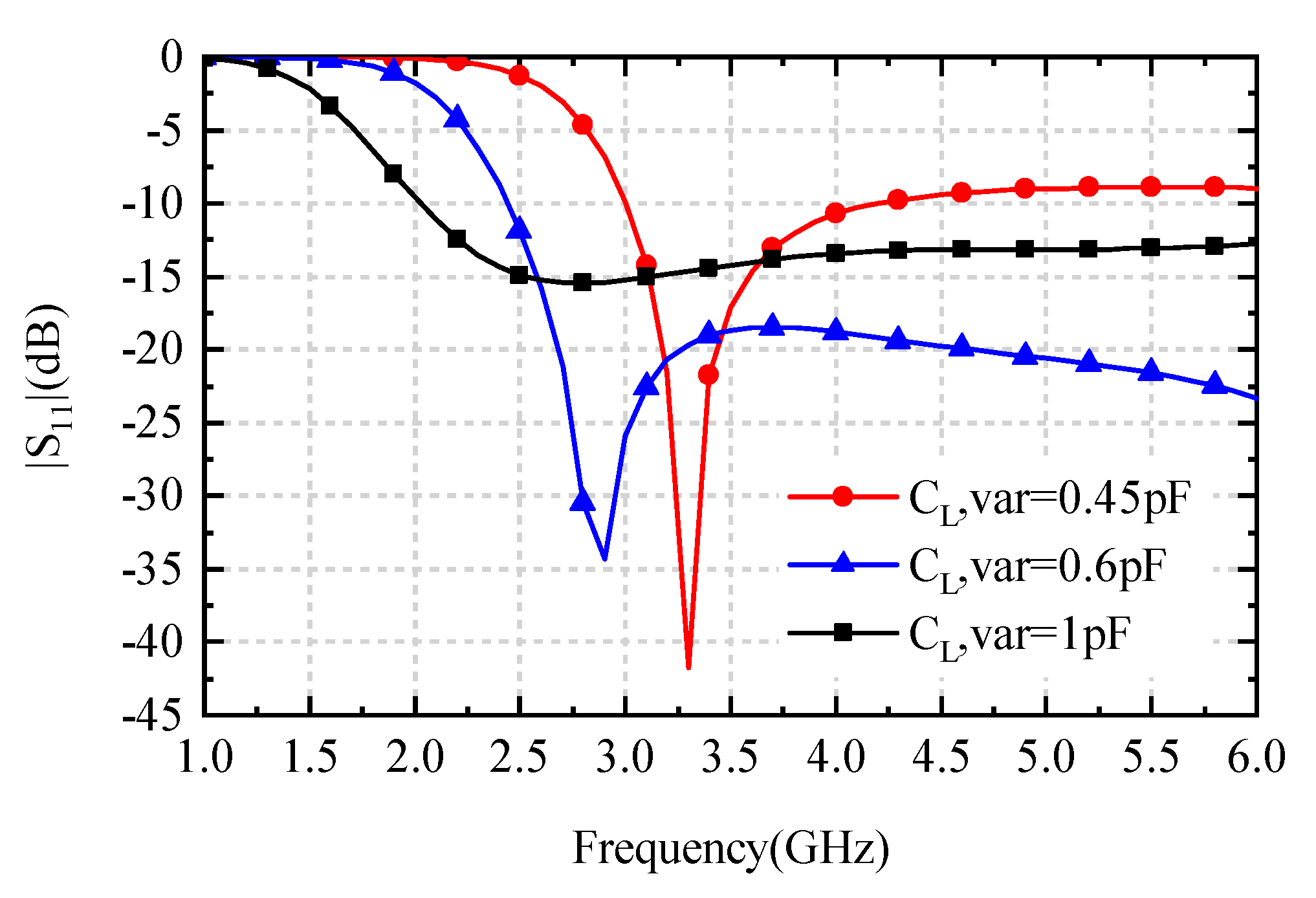
An LWA with 20 cascaded unit cells has a length of about 4λ(λ is the operation wavelength in free space). The scanning performance of the main beam can be predicted using the study described in Section 2.1. However, there are some deviations between the characteristics of the actual LWA and the infinite periodic TL from Section 2.1, in which the mutual coupling effects are ignored among the unit cells. The S11 and S21 of the designed LWA were calculated when the CL,var changed from 0.35 pF to1.9 pF. Figure 6 shows the simulated |S11| and |S21| in dB with CL,var = 0.45 pF, 0.6 pF, and 1.0 pF, respectively. Figure 6 and the results with other loaded capacitances show that the designed 20-unit cell LWA can be matched well at 3.0 GHz; the fractal bandwidth is 13% with |S11| less than −7.5 dB. The slight shift in the frequency comes from the mutual coupling among the unit cells. Besides this, high radiation efficiency was also obtained; the lowest radiation efficiency was about 50% when the CL,var changed. The efficiency can be improved by increasing the number of unit cells in the LWA. According to the authors’ calculation, the LWA could reach a high radiation efficiency of over 80% when the length of the LWA is extended to more than 80 unit cells.
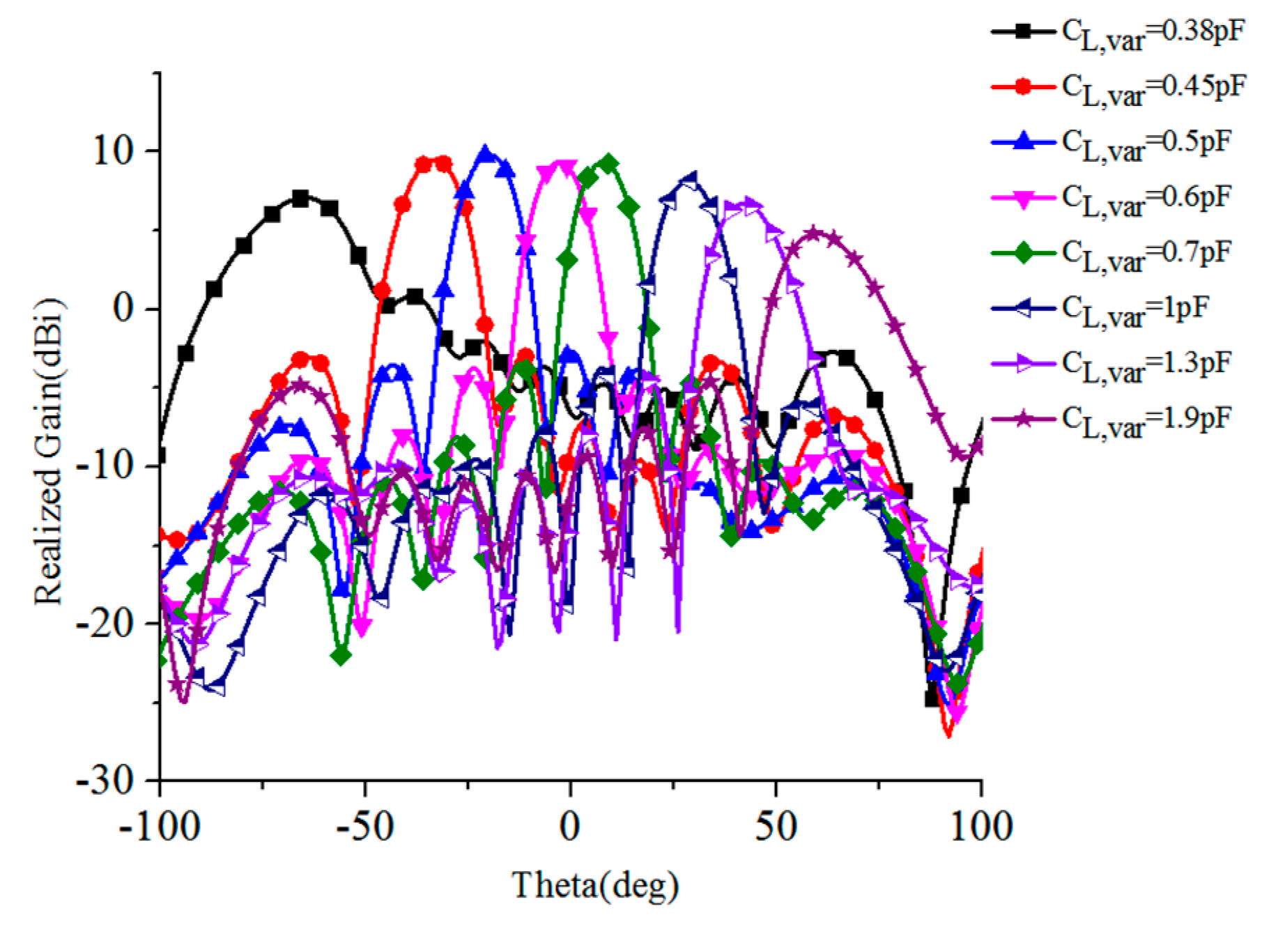
The scanning patterns of the LWA at 3.0 GHz are shown in Figure 7. Figure 7 shows that the scanning angles θ0 of−66°, −33°, −20°, 0°, 8°,29°, 42°, and 62°wereachievedwhen the CL,var was equal to 0.38 pF, 0.45 pF, 0.5 pF, 0.6 pF, 0.7 pF, 1 pF, 1.3 pF, and 1.9 pF, respectively. As the capacitance increased, the main beams were steered from the back to the fore gradually; a scanning range of 128° (from −66° to 62°) was obtained when the capacitance of the varactors changed from 0.38 pF to 1.9 pF. The cross-polarization components are shown here due to their lower level as compared with the co-polarization radiation. In addition, the side lobe level (SLL) was also low over the entire beam-scanning range because of the gradual distribution of the current amplitude in the LWA aperture.
It should be noted that broadside radiation is achieved when the CL,var = 0.6 pF in Figure 7. Generally speaking, an unbalanced condition is easy to generate because of the sensibility to broadside radiation. Consequently, it is a common phenomenon in the periodical LWA that the realized gain decreases significantly at the broadside [5,6]. However, for the proposed LWA, the balance condition is satisfied at CL,var = 0.6 pF. Therefore, the stop band and decline of the realized gain do not happen for broadside radiation.
In Figure 7, the peak gain of the scanning beams is 9.9 dBi; the minimum gain of 5.0 dBi appears at scanning angle θ0 = 62°. Gain fluctuation over the entire scanning range is about 4.9 dBi. The main reason for the lower gain at larger radiation angles off the broadside direction is the decrease in the effective aperture area to the direction of low elevation (equivalent to low leakage efficiency). As mentioned in the discussion of radiation efficiency, the gain can also be improved by increasing the number of unit cells in the LWA.
Figure 8a shows the scanning angles versus the CL,var. As mentioned above, the proposed LWA achieves a beam-steering range of 128° with a small gain fluctuation. This excellent beam-scanning ability in a wide angle range comes from the particular LWA structure and the wide capacitance variation range of the loaded varactors. Figure 8b shows the half-power beam width (HPBW) of the scanning beam in the scanning plane (E-plane) with different loaded capacitance values. When the LWA radiates to a larger angle off the broadside direction, the HPBW becomes wider.
The reason behind this phenomenon is the same as that given in the gain variation analysis mentioned above. Table 3 shows a comparison among the performances of several previous studies [19,20,21] with the proposed LWA. It shows that the proposed LWA achieves the largest beam-scanning range.

3.3. Fabrication and Measurement

The LWA was fabricated and measured to verify the design concept. Since a substrate with a length of 4λ (40 cm) and its etching process are not available in our laboratory, a prototype of a 10-unit cascaded LWA was fabricated to demonstrate the performance of the proposed LWA, which is shown in Figure 9a,b. The measured |S11| and |S21|in dB with three different bias voltages of the varactors are shown in Figure 10; those with other DC bias voltages are omitted in this figure for brevity. The measured results indicate that the LWA can be matched well at around 3.0 GHz, which is similar to the designed results of the 20-unitcascaded LWA (see Figure 6).
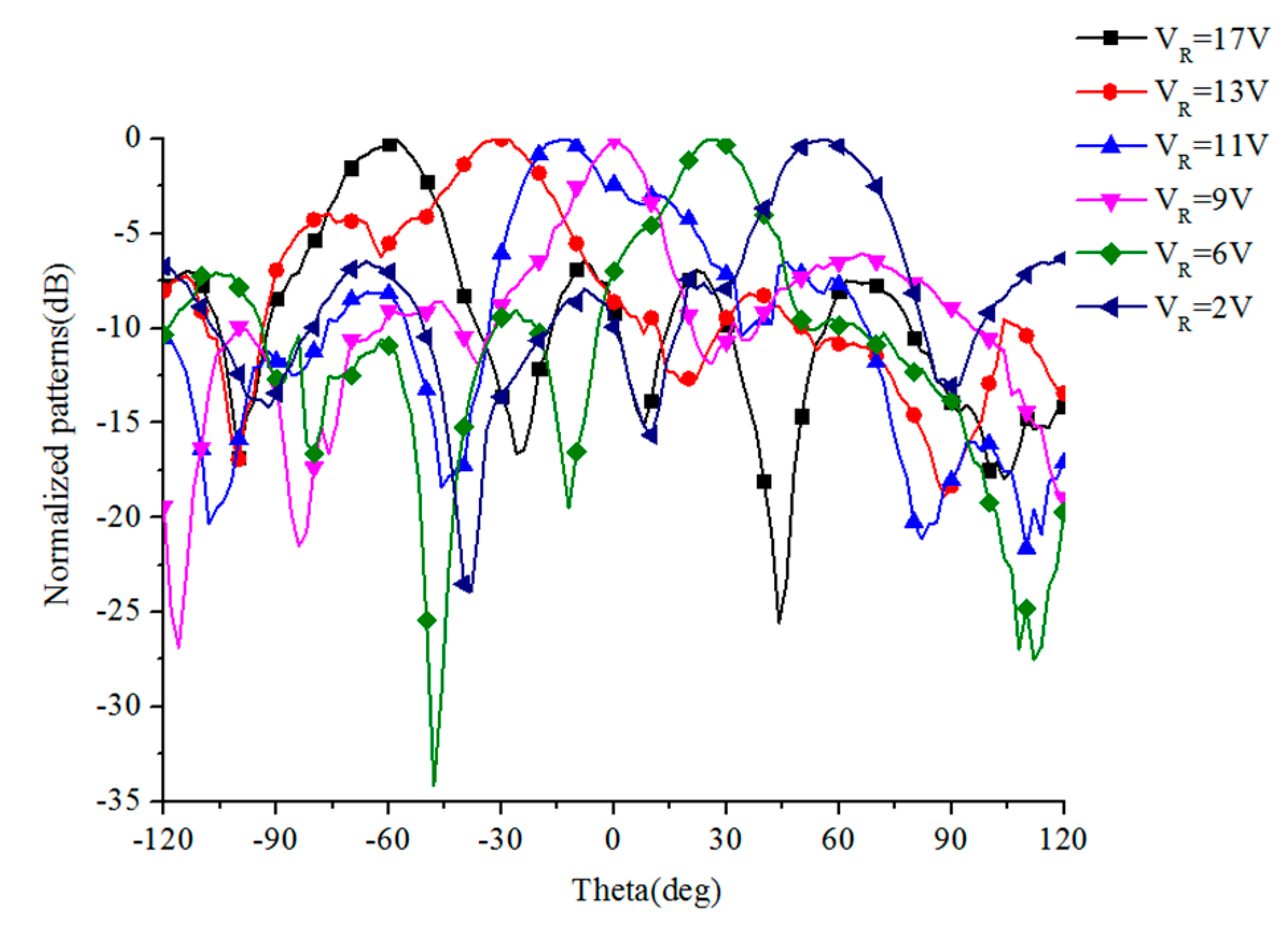
Figure 9cshows the measurement installation of the far field radiation pattern in the anechoic chamber. Figure 11 shows the measured normalized radiation patterns in co-polarization under different DC bias voltages of the loaded varactors. A scanning range from −60° to 60°was observed when the applied voltage varied from 17 V to 2 V. Similarly, low SLL characteristics were still observed, as shown in the simulations in Figure 7. By comparing Figure 11 with Figure 7, it can be seen that the measured scanning range of the main beam matches that of the designed 20-unit cascaded LWA. On the whole, the simple radiation structure and DC feed network for the varactors result in only a small deviation between the experimental results and the proposed LWA’s results. This slight deviation between simulation and measurement is due to the fabrication tolerances and the used varactor model.
The measured beam-scanning range of the proposed LWA is listed in Table 3, which is compared with the three previous LWAs proposed in [19,20,21]. Just as with the simulated results, the proposed LWA possesses the widest beam-scanning range. This study demonstrates that the proposed LWA has broad application prospects in wide angle scanning applications.

4. Conclusions

This paper proposes a frequency-independent wide-angle scanning LWA based on a CRLH TL. It operates at a frequency of3.0 GHz with a fractal bandwidth of 13%. ACPWG structure is used for the frequency-independent LWA. The phase constant of the fundamental mode in the LWA is controlled by changing the applied DC voltage of the periodically loaded varactors. A scanning range of 128° (from −66° to 62°) is achieved with a low SLL and a low gain fluctuation by the designed 20-unit cell LWA. The peak gain is 9.9 dBi and the lowest radiation efficiency is about 50% during beam-scanning. The experimental verification is completed by fabricating and measuring a prototype—a 10-unit cascaded LWA.

Author Contributions

Antenna design, investigation and data curation, S.X. (Shaoyi Xie) and J.L.; Formal analysis, J.L.; Funding acquisition and project administration, G.D.; Methodology, simulation and writing, J.F. and S.X. (Shaoqiu Xiao); All authors have read and agreed to the published version of the manuscript.

Funding

This work was supported in part by the National Natural Science Foundation of China under Grant 61731005, and in part by the Pre-research Foundation of National Defense of China under Grant 170441413086.

Conflicts of Interest

The authors declare no conflict of interest.

References

  1. Oliner, A.A. Leakage from higher modes on microstrip line with application to antennas. Radio Sci. 1987, 22, 907–912. [Google Scholar] [CrossRef]
  2. Jackson, D.R. Leaky-wave antennas. In Frontiers in Antennas: Next Generation Design &Engineering; Caloz, C., Jackson, D.R., Itoh, T., Eds.; McGraw-Hill: New York, NY, USA, 2011; pp. 339–406. [Google Scholar]
  3. Liu, J.; Jackson, D.R.; Long, Y. Substrate Integrated Waveguide (SIW) Leaky-Wave Antenna with Transverse Slots. IEEE Trans. Antennas Propag. 2011, 60, 20–29. [Google Scholar] [CrossRef]
  4. Shelby, R.A.; Smith, D.R.; Schultz, S. Experimental Verification of a Negative Index of Refraction. Science 2001, 292, 77–79. [Google Scholar] [CrossRef] [PubMed] [Green Version]
  5. Caloz, C.; Itoh, T. Electromagnetic Metamaterials: Transmission Line Theory and Microwave Applications; Wiley: Hoboken, NJ, USA, 2005; pp. 261–313. [Google Scholar]
  6. Eleftheriades, G.V.; BalmainK, G. Negativere Fraction Metamaterials: Fundamental Principles and Applications; Wiley: Hoboken, NJ, USA, 2005; pp. 53–92. [Google Scholar]
  7. Sanada, A.; Kimura, M.; Awai, I.; Kubo, H.; Caloz, C.; Itoh, T. A planar zeroth order resonator antenna using left-handed transmission line. In Proceedings of the 34th European Microwave Conference, Amsterdam, The Netherlands, 12–14 October 2004. [Google Scholar]
  8. Caloz, C.; Sanada, A.; Itoh, T. A novel composite right-/left-handed coupled-line directional coupler with arbitrary coupling level and broad bandwidth. IEEE Trans. Microw. Theory Tech. 2004, 52, 980–992. [Google Scholar] [CrossRef]
  9. Dong, Y.; Itoh, T. Substrate integrated composite right-/left-handed leaky-wave structure for polarization-flexible antenna application. IEEE Trans. Antenna Propag. 2012, 60, 760–771. [Google Scholar] [CrossRef]
  10. Cao, W.; Chen, Z.N.; Hong, W.; Zhang, B.; Liu, A. A beam scanning leaky-wave slot antenna with enhanced scanning angle range and flat gain characteristic using composite phase-shifting transmission line. IEEE Trans. Antennas Propag. 2014, 62, 5871–5875. [Google Scholar] [CrossRef]
  11. Yang, Q.; Zhao, X.; Zhang, Y. Composite right/left-handed ridge substrate integrated waveguide slot array antennas. IEEE Trans. Antennas Propag. 2014, 62, 2311–2316. [Google Scholar] [CrossRef]
  12. Nasimuddin; Chen, Z.N.; Qing, X. Multilayered composite right/left-handed leaky-wave antenna with consistent gain. IEEE Trans. Antennas Propag. 2012, 60, 5056–5062. [Google Scholar] [CrossRef]
  13. Saghati, A.P.; Mirsalehi, M.M.; Neshati, M.H. A HMSIW circularly polarized leaky-wave antenna with backward, broadside, and forward radiation. IEEE Antennas Wirel. Propag. Lett. 2014, 13, 451–454. [Google Scholar] [CrossRef]
  14. Huang, L.; Chiao, J.-C.; De Lisio, M. An electronically switchable leaky wave antenna. IEEE Trans. Antennas Propag. 2000, 48, 1769–1772. [Google Scholar] [CrossRef]
  15. Ouedraogo, R.O.; Rothwell, E.; Greetis, B.J. A reconfigurable microstrip leaky-wave antenna with a broadly steerable beam. IEEE Trans. Antennas Propag. 2011, 59, 3080–3083. [Google Scholar] [CrossRef]
  16. Karmokar, D.K.; Esselle, K.P.; Hay, S.G. Fixed-Frequency beam steering of microstrip leaky-wave antennas using binary switches. IEEE Trans. Antennas Propag. 2016, 64, 2146–2154. [Google Scholar] [CrossRef]
  17. Sajin, G.; Simion, S.; Craciunoiu, F.; Muller, A.; Bunea, A.C. Frequency tuning of a CRLH CPW antenna on ferrite substrate by magnetic biasing field. In Proceedings of the 39th European Microwave Conference, Rome, Italy, 28–29 September 2009; pp. 1283–1286. [Google Scholar]
  18. Che, B.-J.; Jin, T.; Erni, D.; Meng, F.-Y.; Lyu, Y.-L.; Wu, Q. Electrically controllable composite right/left-handed leaky-wave antenna using liquid crystals in PCB technology. IEEE Trans. Components Packag. Manuf. Technol. 2017, 7, 1331–1342. [Google Scholar] [CrossRef]
  19. Lim, S.; Caloz, C.; Itoh, T. Metamaterial-based electronically controlled transmission-line structure as a novel leaky-wave antenna with tunable radiation angle and beamwidth. IEEE Trans. Microw. Theory Tech. 2005, 53, 161–173. [Google Scholar] [CrossRef]
  20. Suntives, A.; Hum, S.V. A fixed-frequency beam-steerable half-mode substrate integrated waveguide leaky-wave antenna. IEEE Trans. Antennas Propag. 2012, 60, 2540–2544. [Google Scholar] [CrossRef]
  21. Fu, J.-H.; Li, A.; Chen, W.; Lv, B.; Wang, Z.; Li, P.; Wu, Q. An electrically controlled CRLH-inspired circularly polarized leaky-wave antenna. IEEE Antennas Wirel. Propag. Lett. 2016, 16, 760–763. [Google Scholar] [CrossRef]
  22. Lee, N.; Lee, S.; Cheon, C.; Kwon, Y. A two-dimensional beam scanning antenna array using composite right/left handed microstrip leaky-wave antennas. In Proceedings of the 2007 IEEE/MTT-S International Microwave Symposium, Honolulu, HI, USA, 3–8 June 2007; pp. 1883–1886. [Google Scholar]
  23. Kaneda, T.; Sanada, A.; Kubo, H. Design of an 8-element planar composite right/left-handed leaky wave antenna array for 2-D beam steering. In Proceedings of the 2006 Asia-Pacific Microwave Conference, Yokohama, Japan, 12–15 December 2006; pp. 1067–1070. [Google Scholar]
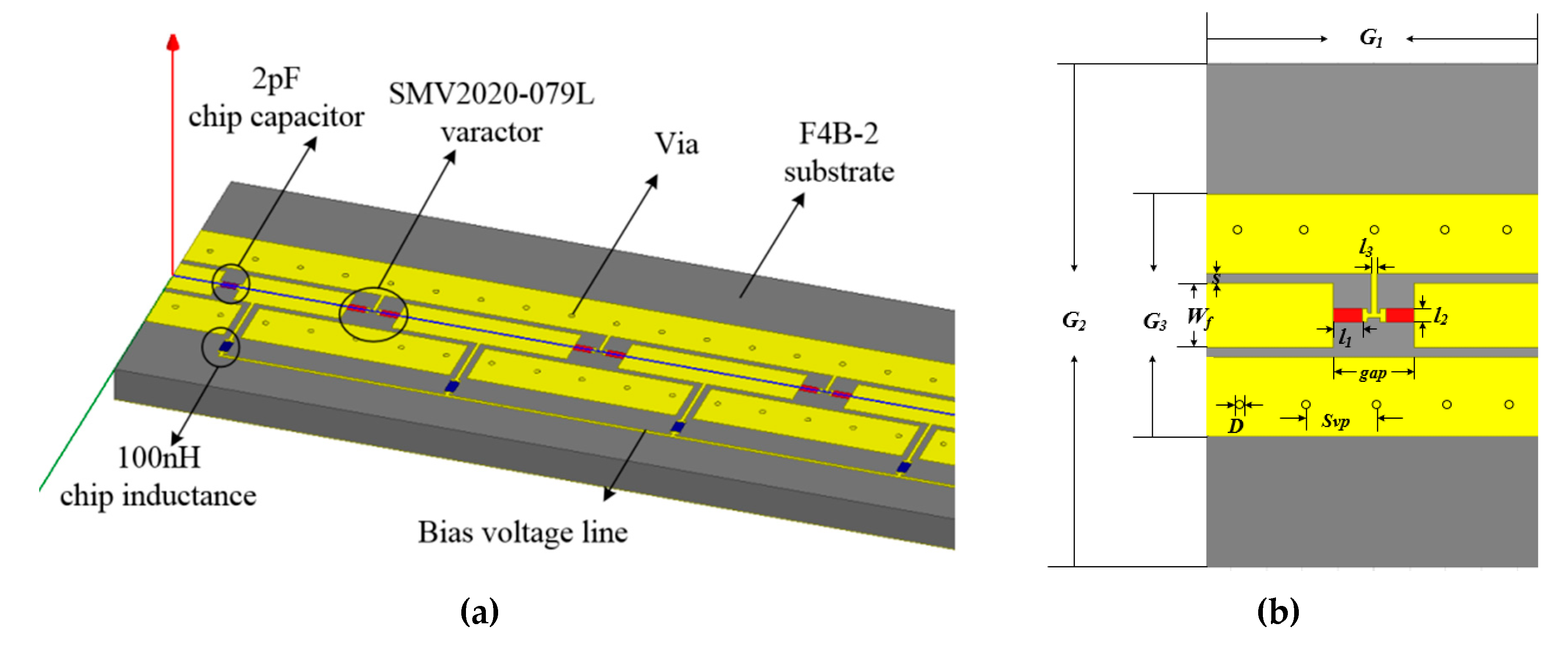
Figure 1. Scheme of the proposed leaky-wave antenna (LWA). (a) Structure of the LWA; (b) Top view of the unit cell.
Applsci 10 01927 g001
Figure 2. Equivalent circuit model of the unit cell.
Applsci 10 01927 g002
Figure 3. |S11| of the unit with different capacitance values.
Applsci 10 01927 g003
Figure 4. Dispersion diagram of the unit cell with various capacitances of varactors.
Applsci 10 01927 g004
Figure 5. Extracted Bloch impendence of the unit cell with CL,var = 1.3 pF.
Applsci 10 01927 g005
Figure 6. |S11| and |S21|of a 20-cell LWA with different capacitance values. (a) |S11|; (b) |S21|.
Applsci 10 01927 g006
Figure 7. Simulated radiation patterns with capacitance varied from 0.38 pF to 1.9 pF.
Applsci 10 01927 g007
Figure 8. Scanning angle and half-power beamwidth (HPBW) of the LWA versus CL,var. (a) Scanning angle; (b) HPBW.
Applsci 10 01927 g008
Figure 9. Photograph of the fabricated 10-unit LWA prototype. (a) Top view; (b) Bottom view; (c) Measurement installation.
Applsci 10 01927 g009
Figure 10. Measured S-parameters of the overall antenna. (a) S11; (b) S21.
Applsci 10 01927 g010
Figure 11. Measured normalized radiation patterns under different bias voltages.
Applsci 10 01927 g011
Table 1. Dimensions of the unit cell(unit:mm).
G1G2G3WfSSvp
20311540.64
Dgapl1l2l3
0.54.51.60.80.3
Table 2. Extracted equivalent circuit model parameters at 3.2 GHz.
5 V10 V15 V20 V
CL,var(pF)1.190.570.410.35
LL(nH)1.821.531.010.77
CR(pF)1.95
LR(nH)9.78
Table 3. Comparison of electronically controlled composite right/left-handed (CRLH) LWAs.
Ref.Simulated Scanning RangeMeasured Scanning RangeOverall LengthRealized Gain (dBi)
[21]−38°–+30°−17°–+40°3.25λ3.1–6.2
[20]−38.6°–+53.3°−31°–+35°3.25λ7.8–11.3
[19]−49°–+50°−35°–+38°5.87λ−7.0–18.0
This work−66°–+62°−60°–+60°5–9.9 1
1 The simulated realized gain was adopted because only a prototype with a length of 2λwas measured in this work.