Article

Insights into the Effect of WJ-7 Fastener Rubber Pad to Vehicle-Rail-Viaduct Coupled Dynamics

1
Engineering Research Center of Railway Environment Vibration and Noise, Ministry of Education, East China Jiaotong University, Nanchang 330013, China
2
Faculty of Engineering, Lusofona University, 1749-024 Lisboa, Portugal
*
Author to whom correspondence should be addressed.
Appl. Sci. 2020, 10(5), 1889; https://doi.org/10.3390/app10051889
Submission received: 23 February 2020 / Revised: 5 March 2020 / Accepted: 6 March 2020 / Published: 10 March 2020
(This article belongs to the Section Acoustics and Vibrations)

Abstract

:
The high-speed railway (HSR) has been a long-term hotspot in both scientific and engineering societies to enhance the long-term high quality HSR service. This study aims to investigate the WJ-7B type small resistance fastener rubber pad applied in HSR, and temperature sweep test is applied to determine the mechanical parameters of the fastener rubber pad, which are hereafter introduced into the vehicle-track-viaduct vertical coupling model via dynamic flexibility method. The track irregularity spectrum is considered as fixed-point excitation to investigate the temperature-dependent effect of fastener rubber pad on the dynamic responses. The results reveal that the rigidity of the fastener rubber pad is low temperature sensitive and high temperature stable, and the temperature variation has little effect on the vertical dynamic responses of the vehicle. The dynamic flexibility of the rail increases in amplitude and the dominant frequency decreases as the temperature of the fastener rubber pad increases. The vertical dynamic responses of the wheel-rail force, the wheelset and the rail-viaduct system gradually decrease as the temperature of the fastener rubber pad increases, and the peak frequency follows the similar rule. While under high temperature circumstances, the temperature dependent stiffness of the fastener rubber pad has little influence on the peak of the dominant frequency in the vertical dynamic response of the track-viaduct system.

1. Introduction

In recent years, high-speed railway (HSR) has been widely constructed in a lot of countries and HSR has also extensively transported a large amount of passengers and vast amount of goods, which enables the possibility of long-distance fast travelling and fast goods transportation. Meanwhile, as wide use of HSR, the corresponded problems such as vehicle-induced vibration have made the vehicle-rail-viaduct coupling system worse and worse. An in-depth understanding of the vehicle-rail-viaduct coupling system under complex circumstances shall be indispensable for enhancing the quality and long-term service of HSR infrastructure system [1,2,3,4]. For instance, in [3], the power flow method is applied to analyze the dominant vibration frequencies of the rail bridges for structure-born noise; in [4], the acoustic modal contribution analysis is applied to study the structural noise mitigation performance for the box-girder viaduct.
In terms of the HSR infrastructure system, various advancements have been developed and also applied in the engineering, such as the China Railway Track System (CRTS) series slabs [5]. In addition to slabs, the fastener serves as an essential component to mitigate the vibration in the rail system. The fastener has several categories depending on various conditions; for instance, the fastener for normal speed railway systems shall differ from those applied for the HSR system. The HSR system has more than 10 kinds of fasteners, which are designed regardless of distinct engineering circumstances. Figure 1 illustrates two kinds of fasteners and their rubber pads. The mechanical properties of the fasteners can largely affect the dynamic responses of the vehicle-rail-viaduct coupling system [5,6]. In the fastener’s system, the stiffness of the fastener rubber pad contributes 94% to the whole stiffness of the fastener’s system, and therefore, the stiffness of the fastener rubber pad can be considered as the whole stiffness of the fastener’s system [7]. Since the fastener rubber pad is made of rubber, the stiffness has close relation to the temperature [8]. Considering such temperature-dependent phenomena, extensive investigations have been conducted for studying certain effects. Ahmad et al. [9] studied the temperature-dependent stiffness of the rubber in the dynamic vibration absorber; Zhao et al. [10] conducted temperature sweep tests for rubber, and analyzed the temperature-dependent stiffness of rubber material; Wei et al. [11,12,13] investigated temperature-dependent stiffness of the fasteners in the subway system, and studied the nonlinear behavior of the temperature dependent stiffness of the fasteners; Liu [14] conducted temperature sweep tests for the fastener rubber pad, and found that at low temperatures, the fastener rubber pad shows low temperature sensitive performance, which further affects the vibration responses of the coupled system.
As mentioned above, although certain investigations have been done for the fastener rubber pad—a kind of viscoelastic damping material [15,16,17,18,19], not too many studies can be found for the temperature dependent effect of the fastener rubber pad to the dynamic responses of the HSR system [16,17,18,19,20,21]. For instance, the effect of the rail fastener on the railway vehicle interior noise is investigated in [16], in order to study the temperature dependent stiffness of the fastener rubber pad, which further affects the dynamic responses of the vehicle-rail-viaduct coupling system.
This study takes the WJ-7B small resistance fastener rubber pad as objective, and Dynamic Mechanical Analysis (DMA) is applied for temperature sweep tests in order to obtain the mechanical properties of the WJ-7B small resistance fastener rubber pad; the dynamic flexibility method is then applied to construct the vehicle-rail-viaduct coupling model, by incorporating with the measured mechanical properties, the dynamic responses for each subsystem including the vehicle, rail, and viaduct are determined using track irregularity spectrum as fixed location excitation. The temperature dependent stiffness of the WJ-7B small resistance fastener rubber pad is analyzed considering its further influence to the dynamic responses of subsystems.

2. Fundamentals of Dynamic Flexibility Method

This study takes the CRH380A high-speed train and 32-m box-girder viaduct for instance, illustrated in Figure 2a; the dynamic flexibility method is employed to build the vehicle-rail-viaduct coupling model, depicted in Figure 2b, in the frequency domain. As shown in Figure 2b, this study solely concerns the vertical vibration, and the vehicle is modeled with half as 10 degrees of freedom (DOF) along the rail direction. The rail is modeled with Timoshenko beam, and the fastener, the cement-emulsified asphalt (CA) mortar and the viaduct bearing are modeled with discrete spring damping elements, the slab is modeled with free-free Euler-Bernoulli beam, and the viaduct is modeled with simply supported Euler beam.
The vehicle-rail-viaduct coupling model is built firstly in frequency domain, by incorporating the dynamic flexibility of each sub-system with the track irregularity spectrum of the rail, the wheel-rail contact force is then obtained; and by substituting the wheel-rail contact force into the dynamic motion equation, the responses of each subsystem including vehicle, rail, and viaduct are eventually determined, respectively.

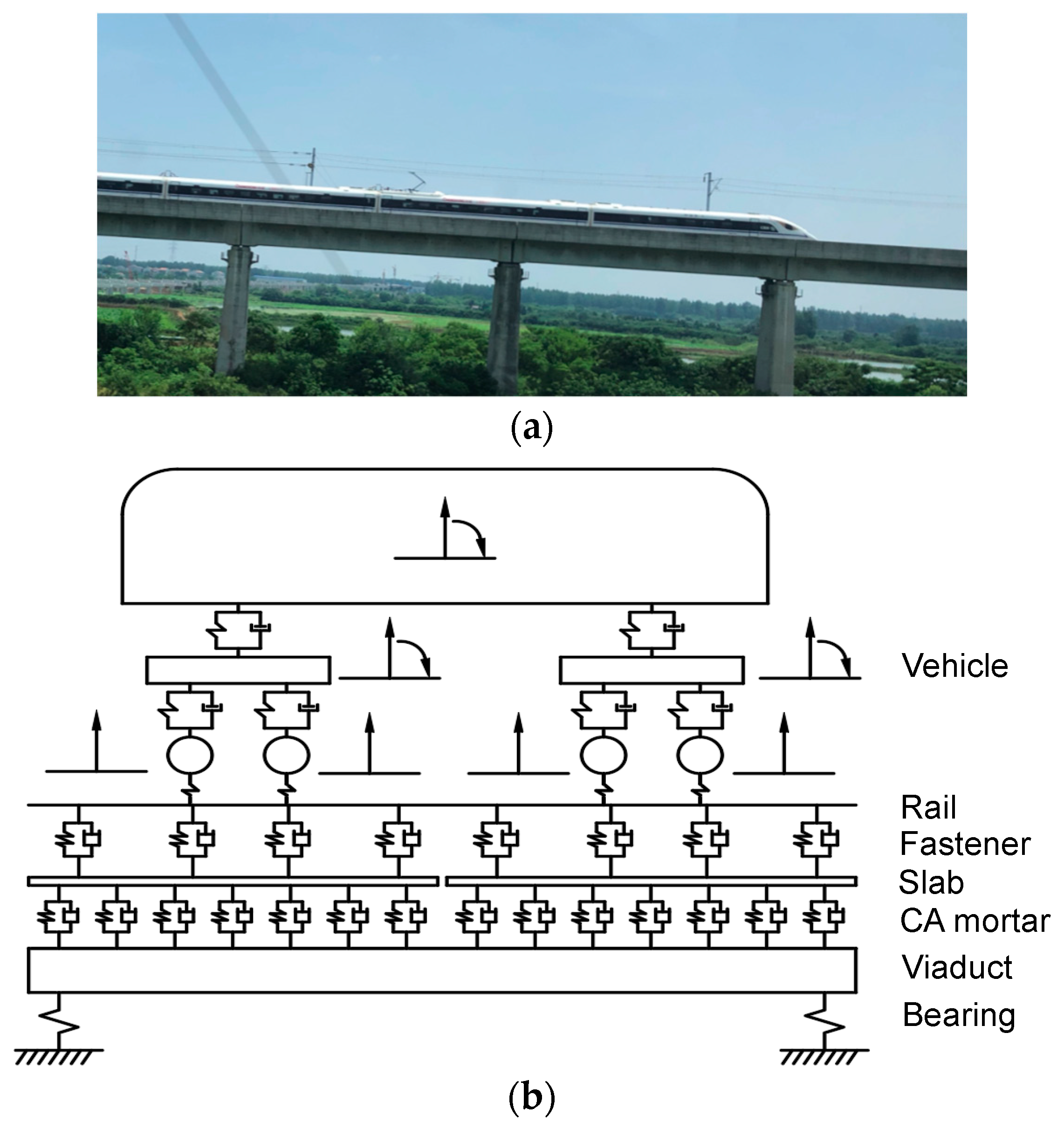
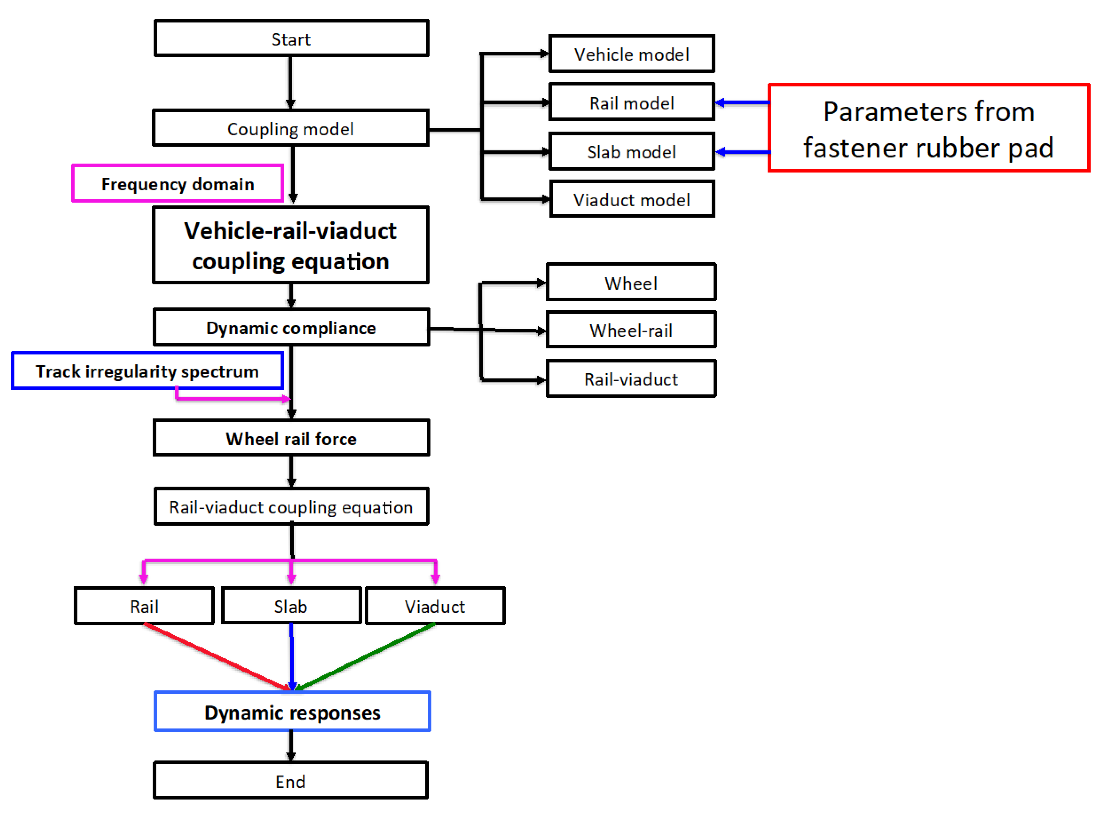
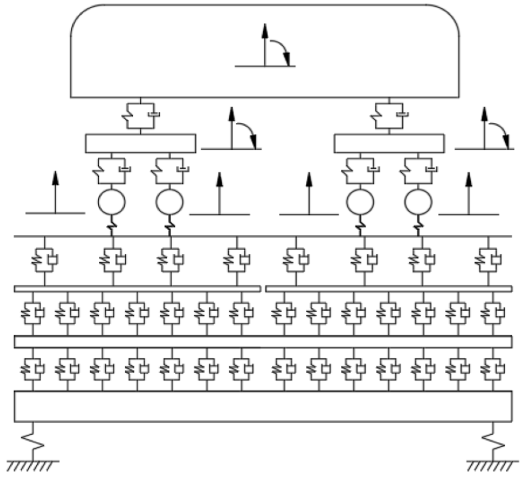
2.1. Vehicle-Rail-Viaduct Coupling Model via Dynamic Flexibility Method

The vertical wheel rail contact force is assumed to be harmonic, the displacement of the vehicle system follows
Z V ( ω ) = p ( ω ) ω 2 M V + i ω C V + K V
where Zv means the displacement of the vehicle system, Mv, Kv and Cv indicate the mass, stiffness and damping, respectively. p(ω) represents the vertical rail-wheel force, and ω denotes the excitation circular frequency.
This study employs Timoshenko beam to model the rail, according to superposition theory for the wheel rail interaction vibration analysis, the displacement in frequency domain for the rail follows
z r ( x ) = w = 1 N w β r ( x , x w ) P w n = 1 N β r ( x , x n ) K f z r ( x n )
where β r ( x , x w ) denotes the displacement at x location when acting unit force at xw in the rail, xw indicates the contacting point for the wth wheel rail, Pw means the wth wheel rail contact force for the wheelset, Nw indicates the amount of the wheelsets; Kfzr(xn) represents the fastener’s force when nth fastener acts on the xn location of the rail. N represents the amount of the fasteners.
The slab is modeled with free-free Euler-Bernoulli beam, and in the frequency domain, its displacement follows
Z s ( x ) = n = 1 N β s ( x , x n ) F f n m = 1 M β s ( x , x m ) F j m
where β s ( x , x n ) indicates the displacement at the x location of the slab when unit force is loaded on xn location of the slab, Ffn denotes the fastener’s force at location xn of the slab. N means the amount of the fasteners. Fjm represents the discrete spring force at xm in the CA mortar of the slab; M illustrates the amount of the discrete spring dampers in the CA mortar.
The box girder viaduct is considered as simply-supported Euler beam, and by using the modal superposition method, the displacement of the box-girder viaduct follows
Z b ( x ) = n = 1 N β b ( x , x m ) F j m h = 1 2 ( x , x z h ) F z h
where β b ( x , x m ) represents the responses at x location when unit force is loaded at xm location of the viaduct, Fzh denotes the hth bearing reaction force of the viaduct.
When constructing the vehicle-rail-viaduct coupling model, the fastener, the CA mortar, and the bearing are modeled with discrete spring damping elements, and then the fastener’s force Ffn, the discrete spring force at CA mortar Fjm, and the bearing reaction force Fzh can be illustrated as
{ F f n = K f ( z r ( x n ) z s ( x n ) ) F j m = K j ( z s ( x m ) z b ( x m ) ) F z h = K z z b ( x h )
where Kf denotes the complex stiffness of the fastener, Kj means the complex stiffness of the discrete spring damper element in the CA mortar, Kz indicates the complex stiffness of the viaduct bearing.
{ K f = k f ( 1 + i η f ) K j = k j ( 1 + i η j ) K z = k z ( 1 + i η z )
where kf means the stiffness of the fastener, ηf denotes the loss factor of fastener, kj indicates the discrete spring element stiffness of the CA mortar, ηj represents the loss factor of the CA mortar discrete spring element, kz denotes the stiffness of the viaduct bearing, ηz represents the loss factor of the viaduct bearing stiffness.
Substituting Equation (5) into Equations (2)–(4) yields the following equation
[ β K ] { Z } = { P }
where β means the dynamic flexibility matrix of the whole rail layer, K represents the full complex stiffness of the slab-rail-viaduct system, Z indicates the displacement matrix of the rail, slab and viaduct; P illustrates the load matrix.

2.2. Dynamic Flexibility Calculation for the Wheel

Separation of variables method (so called Fourier method) is applied to Equation (1), the dynamic flexibility of the wheel can be obtained and is expressed as
β i j V = Z i j W P j ,   i ,   j   =   1 ,   2 ,   3 ,   4
where Z i j W indicates the displacement at the ith contacting point of the wheel when the wheel-rail contact force Pj is applied to the jth wheel-rail contacting point; β i j V means the displacement at the ith location of the wheel when unit force is applied to the jth contacting point.

2.3. Dynamic Flexibility for the Wheel Rail Interaction

This study employs the frequency domain model, the linear Hertz contacting model is used to model the wheel-rail interaction [22], and the dynamic flexibility of the wheel-rail interaction follows
β i C = Z δ i P i = 1 K H ,   i =   1 ,   2 ,   3 ,   4
where Z δ i indicates the contacting deformation, KH denotes the contacting stiffness of the wheel-rail.

2.4. The Dynamic Flexibility of the Rail-Viaduct Coupling System

(1) Dynamic flexibility of the rail
The dynamic flexibility of the rail follows [23]
β r ( x 1 , x 2 ) = u 1 e i k 1 | x 1 x 2 | + u 2 e k 2 | x 1 x 2 |
where
k 1 , 2 = ( ω 2 ) { ± ( ρ r E r ( 1 + i η r ) + ρ r κ G r E r ( 1 + i η r ) ) + [ ( ρ r E r ( 1 + i η r ) ρ r κ G r E r ( 1 + i η r ) ) 2 + 4 ρ r A r E r ( 1 + i η r ) I r ω 2 ] 1 2 } 1 2
u 1 = i 2 κ G r E r I r A r ( 1 + i η r ) 2 × ρ r I r ω 2 κ G r A r ( 1 + i η r ) E r I r ( 1 + i η r ) k 1 2 k 1 ( k 1 2 + k 2 2 )
u 2 = i 2 κ G r E r I r A r ( 1 + i η r ) 2 × ρ r I r ω 2 κ G r A r ( 1 + i η r ) E r I r ( 1 + i η r ) k 2 2 k 2 ( k 1 2 + k 2 2 )
where ρr, Er, Gr, Ir, Ar, κ, and ηr indicate density, Young’s modulus, shear modulus, sectional inertia moment, section area, shear coefficient, and loss factor of the rail, respectively.
(2) Dynamic flexibility of the slab
The slab is modeled as free-free Euler-Bernoulli beam, and its dynamic flexibility follows
β b ( x 1 , x 2 ) = n = 1 N φ n ( x 1 ) φ n ( x 2 ) [ ω n 2 ( 1 + i η ) ω 2 ]
where φn(x) indicates the nth order mode shape at x location, ωn represents nth order resonant frequency for the beam, η means the loss factor for the slab, N denotes the order.
(3) Dynamic flexibility of the viaducts
Viaduct is modeled as simply supported Euler beam, and its dynamic flexibility follows
β b ( x 2 , x 1 ) = n = 1 N M B W b n ( x 2 ) W b n ( x 1 ) ( 1 + i η b ) ω b n 2 ω 2
where Wbn indicates the nth order mode shape, ωbn indicates the nth order resonant frequency, NMB means the amount of modes.
Substituting Equations (10), (14), (15) into Equation (7) determines the dynamic flexibility of the rail-viaduct interaction system, it is expressed as
β i j T B = z i j T B p j ,   i , j   =   1 ,   2 ,   3 ,   4
where z i j T B indicates the displacement of ith contacting point of the rail-viaduct coupling system when wheel-rail interaction Pj is loaded at jth wheel rail contacting point, β i j T B means the displacement at the ith location of the rail-viaduct coupling system when unit harmonic force is applied to the jth wheel rail contacting point.

2.5. Harmonic Analysis for the Vehicle-Rail-Viaduct Coupling System

The harmonic response analysis is applied to the vehicle-rail-viaduct coupling responses [24], assuming the roughness amplitude spectrum to be r(ω), when the train is passing, due to the distinct locations of the wheelsets, the excitations are not concurrently loaded at different wheel rail contacting points, the corresponding track irregularity can be expressed as
R ( ω ) = { 1 e 2 i ω l t / V e 2 i ω l c / V e 2 i ω ( l t + l c ) / V } T r ( ω )
With the aforementioned constructed vehicle-rail-viaduct coupling model, the dynamic wheel-rail contact force Pwr can be expressed as
P w r = ( β V + β T B + β c ) 1 R ( ω )
Substituting the dynamic wheel-rail force Pwr into Equations (1) and (7) can determine displacements of the vehicle, the rail, the slab, and the viaduct, illustrated as Z(ω), respectively.
With the displacements of each subsystem, the corresponding accelerations can be determined, and the accelerations can be expressed as
a ( ω ) = ω 2 × Z ( ω )
where a(ω), Z(ω) indicate the acceleration and displacements for the structures, respectively.
Figure 3 illustrates the flowchart for the investigation of the fastener rubber pad. The dynamic mechanical tests of the fastener rubber pad can obtain the parameters for further analysis via dynamic flexibility method, to unveil certain temperature variation effect of the fastener rubber pad to the dynamic responses of the vehicle-rail-viaduct system. The subsequent sections try to describe the tests in detail.

3. Experimental Tests

3.1. General information for the tests

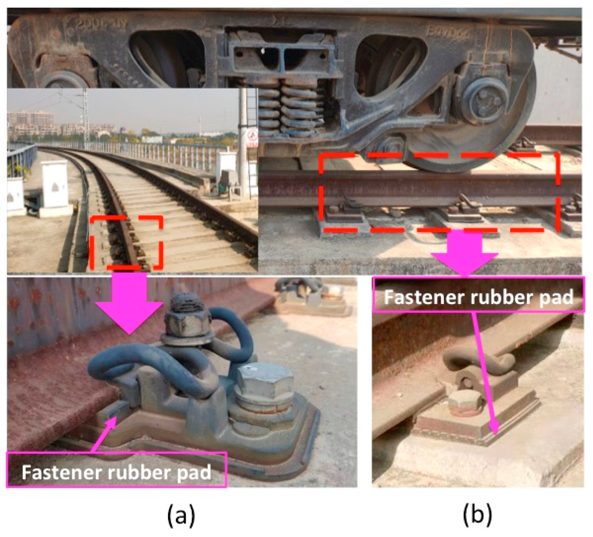
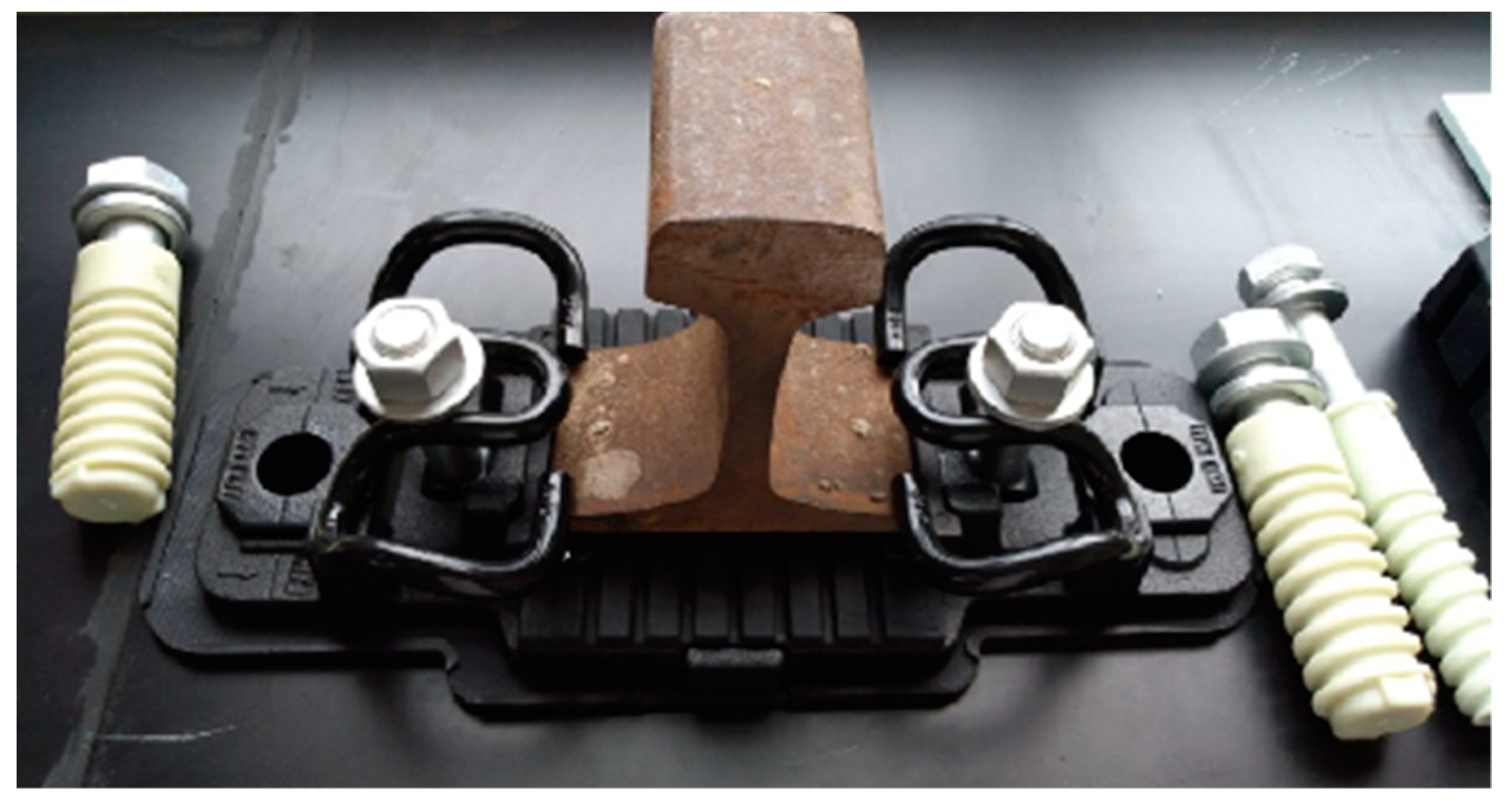
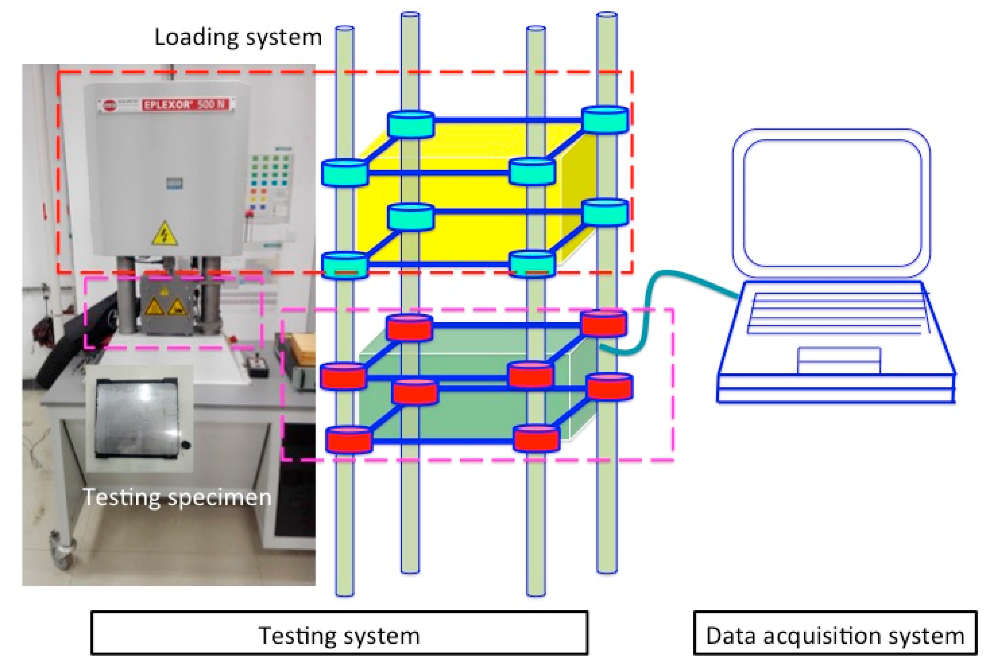
3.1.1. Dynamic Mechanical Tests for the Fastener Rubber Pad

This study takes the WJ-7B small resistance fastener rubber pad from the HSR system as a test objective shown in Figure 4. In Figure 4, the pad below the rail was the fastener rubber pad. The specimen took 15   m m × 10   m m cylinders, the 500 N Dynamic Mechanical Testing Machine, Analyzing and Testing DMA GABO Instruments, shown in Figure 5, enabled the conduction of temperature sweep tests for extracting the temperature dependent Young’s modulus [14]. The testing frequency was set as 2 Hz, and temperature range was [−60, 40] °C. The temperature interval was 20 °C in the temperature sweep test. 20 °C is the typical operating temperature.
The temperature dependent Young’s modulus of the fastener rubber pad is shown in Figure 6a. Below −55 °C, the Young’s modulus of the fastener rubber pad increased as the temperature increased, and under such a low temperature that it was in a glassy state, the Young’s modulus was relatively high; as the temperature increased beyond −55 °C, the Young’s modulus of the fastener rubber pad decreased sharply; and when the temperature increased beyond −20 °C, the Young’s modulus of the fastener rubber pad decreased pretty slowly.
With the available Young’s modulus, the stiffness of the structure can be obtained with Equation (20) and is shown in Figure 6b, the complex stiffness can also be determined with Equation (21) and is demonstrated in Figure 6c (absolute values).
k f = A Y h
where kf indicates the stiffness of the fastener rubber pad, Kf means the complex stiffness of the fastener rubber pad, A and h represent the section area, and thickness of the fastener rubber pad, respectively.

3.1.2. Testing Configuration

As to the dynamic responses analysis of the vehicle-rail-viaduct coupled system, this study employed the testing temperature range [−40, 40] °C for the fastener rubber pad, with 20 °C as interval. Then five scenarios are summarized in Table 1.

3.2. Model Description

3.2.1. Model Properties

This study takes the high-speed train CRH380A as example, the parameters are illustrated in Table 2, and the structural parameters for the viaduct are illustrated in Table 3.

3.2.2. Track Irregularity Spectrum of the Rail

The velocity of the train was considered to be 350 km/h, the track irregularity spectrum employed the roughness amplitude spectrum of the rail in ISO 3095:2005 [25]
20 lg ( R r 0 ) = { 18.435 lg λ + 27.194 , 0.01 λ 9.7 , 0.00315 λ < 0.01
λ = 2 π V ω
where r 0 denotes the reference roughness, r 0 = 10−6 m; λ indicates the wavelength (m), V means the velocity of the vehicle.

4. Results Analysis

This section aims to illustrate the effect of fastener rubber pad’s temperature dependent Young’s modulus to the vibration responses of the vehicle-rail-viaduct system. Via the dynamic flexibility method and the constructed vehicle-rail-viaduct coupling model for vertical vibration analysis, the track irregularity spectrum of the rail from ISO 3095:2005 was considered as excitation, and according to the distinct fastener rubber pad’s stiffness under different temperatures, five scenarios were studied for investigating the performances of the vehicle-rail-viaduct coupling vibration, in order to draw out the effect of the fastener rubber pad’s temperature-dependent Young’s modulus.
Figure 7 shows the dynamic flexibility amplitude of the rail-viaduct for all five scenarios. From Figure 7, the dynamic flexibilities of the rail-viaduct for all five scenarios showed peaks around 5 Hz, and the dynamic flexibilities increased as then temperature increased, while the peak frequency shifted leftward; in addition, the peak frequency was the first order resonant frequency of the rail-viaduct vertical coupling system, which implies that the temperature dependent performance of the fastener rubber pad had little effect to such first order resonant frequency; in frequency range [0, 107] Hz, the dynamic flexibilities of the rail-viaduct increased as the temperature increased; in frequency range [107, 144] Hz, the ratios of the peaks of the rail-viaduct’s dynamic flexibilities to the peak under first scenario were 100%, 389.3%, 506.6%, 586.1%, 624.6%. As the temperature increased for the fastener rubber pad, the peaks of the dynamic flexibilities of the rail-viaduct increased, and the resonant frequency peaks shifted leftward. Table 4 gives the exact first order resonant and dominant frequencies for five scenarios. The dominant frequencies change more than the first order resonant frequencies for the same scenario in comparison to the Case #1.
Figure 8 shows the wheel-rail contact forces under five scenarios. From Figure 8, it can be found that: (1) below 20 Hz, the temperature dependent Young’s modulus of the fastener rubber pad of the fastener had little effect to the wheel-rail force; (2) in frequency range [20, 42] Hz, the amplitude of the wheel-rail force increased sharply as the temperature increased; (3) as the temperature increased, the peaks of the wheel-rail forces for all five scenarios decreased, and so did the dominant frequencies; the dominant frequencies for five scenarios were 74, 51, 47, 43 and 42 Hz, respectively; (4) In frequency range [56, 100] Hz, as the temperature decreases, the wheel-rail forces increased.
Figure 9 and Figure 10 illustrate the accelerations of the vehicle body and the wheelset, respectively. Because the responses of the vehicle mainly occupy the frequency range below 20 Hz, this study takes the frequency range [0, 20] Hz for further investigation. From Figure 9, for all five scenarios, the vertical accelerations of the vehicle had little difference, which suggests that the temperature dependent Young’s modulus of the fastener rubber pad had little influence to the vertical responses of the vehicle on such occasion. In Figure 10, for all five scenarios, regarding to the frequency range below 20 Hz, the temperature dependent Young’s modulus of the fastener rubber pad had little influence to the vertical responses of the wheelset; while as temperature increased, the peaks of the vertical accelerations decreased gradually, and the dominant frequencies also decreased.
Table 5 illustrates the peak values and the dominant frequencies from the vertical acceleration of the wheelset for the five scenarios. Both the peak value and the dominant frequency changed greatly for the five scenarios in comparison to the scenario #1.
Figure 11, Figure 12, Figure 13 and Figure 14 illustrate the fastener’s force, accelerations of the rail, slab, and viaduct, respectively. From Figure 11, Figure 12, Figure 13 and Figure 14, the temperature dependent Young’s modulus of the fastener rubber pad had similar influence to the acceleration responses of the rail, slab and viaduct. Taking the acceleration response of the viaduct as example, in frequency range below 30 Hz, the vertical accelerations of the viaduct for all five scenarios had little difference, which suggests that the temperature dependent Young’s modulus of the fastener rubber pad had little influence to the acceleration response of the viaduct; for all five scenarios, the acceleration peaks of the viaduct decreased gradually as the temperature increased; the dominant frequencies were 84 Hz, 49 Hz, 44 Hz, 44 Hz, and 44 Hz, respectively, for five scenarios, which implies that the dominant frequencies decreased to a certain value and tended to be constant as the temperature increased.
From the above discussions, when the temperature increased, the stiffness of the fastener rubber pad decreased more and more slowly, and all the response peaks for carriage, rail, and viaduct decreased; this is because at high temperature, the stiffness of the fastener rubber pad changes very little, this further enables the peaks and dominant frequencies of the accelerations decrease and tend to be constant as the temperature increases; the dominant frequency is mainly affected by the resonant frequency of the coupled wheel rail system.

5. Comparison of Proposed Method with Conventional Method

In order to validate the feasibility of aforementioned method, it has been compared with previous investigations [3,26].

5.1. Case I: Three-Span Bridge

A power flow method is applied to analyze the structure-borne noise in the frequency domain of the three-span bridge with piers [3], where the ANSYS software with 20-node solid elements and single-node mass elements are used to model the three-span bridge, illustrated in Figure 15. Details about the model can be found in [3].
The wheel-rail contact force calculated by the proposed dynamic flexibility method in Figure 16 agrees well with the result determined by power flow method in [3], this suggests the feasibility of the proposed dynamic flexibility method in analyzing the vibration characteristics of the wheel-rail-viaduct coupling systems. The main resonant frequency locates at the frequency around 55 Hz.

5.2. Case II: Multi-Layer Model for Ballastless Track

This section aims to compare the results obtained by the proposed dynamic flexibility method and the results obtained in [26] with taking a multi-layer model for the vehicle-rail-viaduct shown in Figure 17. Details about the vehicle-rail-viaduct system can be found in [26].
Figure 18 shows the dynamic flexibility amplitude obtained by the dynamic flexibility method, the dynamic flexibility of the wheel obtains the peak value at 2 Hz, and decreases as the frequency increases. The dynamic flexibility of the contacting spring keeps constant. These results agree well with the results obtained in [26].
Figure 19 shows the phase of the dynamic flexibility obtained by the dynamic flexibility method, the phase of the contacting spring keeps constant, and the phase of the dynamic flexibility of the rail-viaduct reaches a lower peak at 7 Hz. All these results agree well with the results obtained in [26]. This also implies the feasibility of the proposed method in analyzing the vibration characteristics of the vehicle-rail-viaduct system.

6. Concluding Remarks

This study investigates the WJ-7B small resistance fastener rubber pad from the HSR system via dynamic flexibility method, the mechanical properties of the WJ-7B small resistance fastener rubber pad are determined via temperature sweep tests, and certain measured parameters are incorporated with the track irregularity spectrum as excitation at a given location, the dynamic responses of the vehicle-rail-viaduct coupling system are further identified, the effect of the temperature-dependent stiffness of the small resistance fastener rubber pad to the vehicle, rail and viaduct are eventually analyzed, this method has also been compared with conventional investigations, and conclusions are summarized as follows:
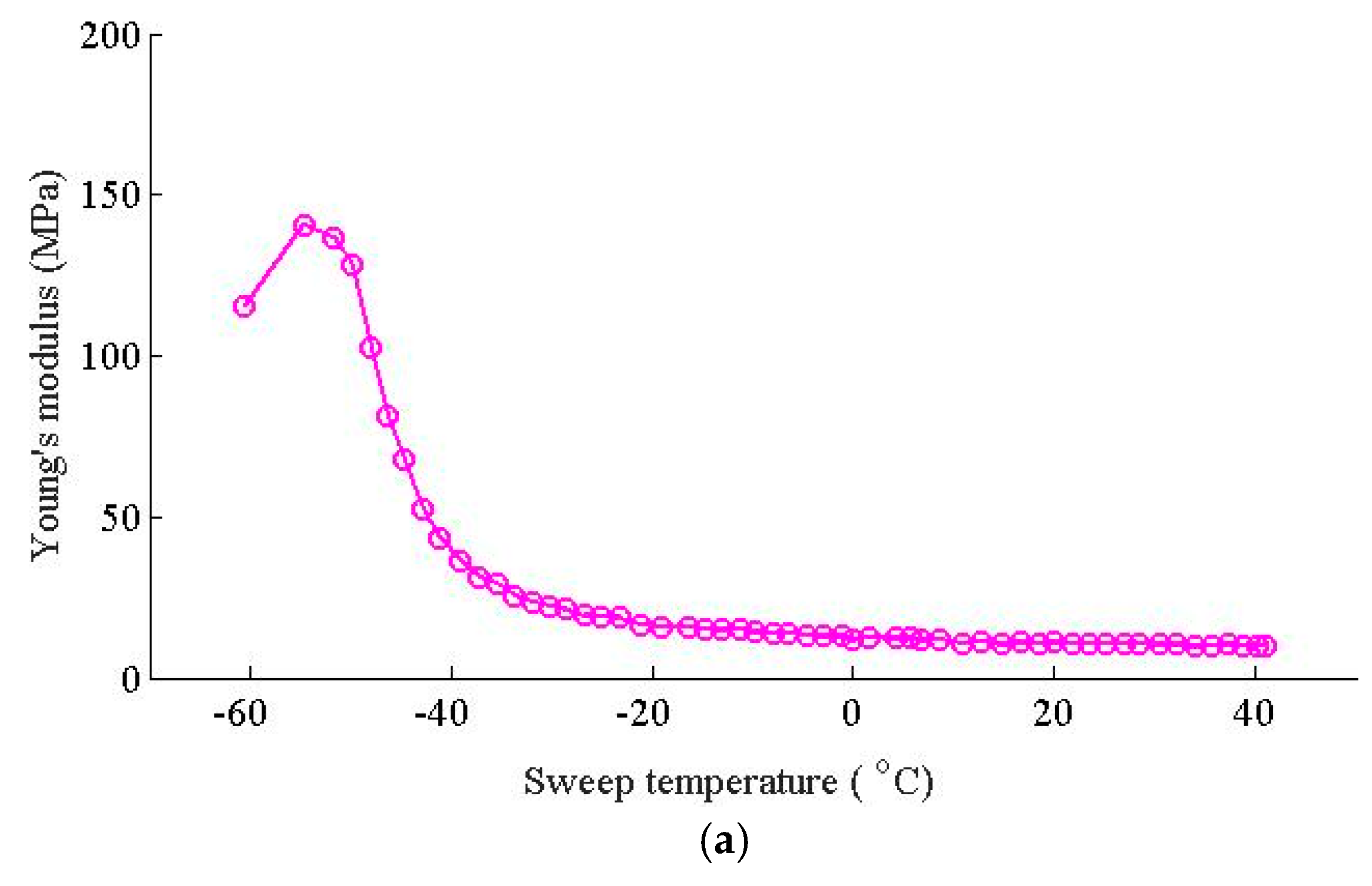
  • The WJ-7B small resistance fastener rubber pad behaves sensitive at low temperatures, while stable at high temperatures. The WJ-7B small resistance fastener rubber pad has relatively high stiffness at low temperatures; during the transition period from a glassy state to a rubbery state, the stiffness of the WJ-7B small resistance fasteners declines sharply; while at relatively high temperatures, the stiffness of the WJ-7B small resistance fasteners keeps stable, with little change versus the temperature change.
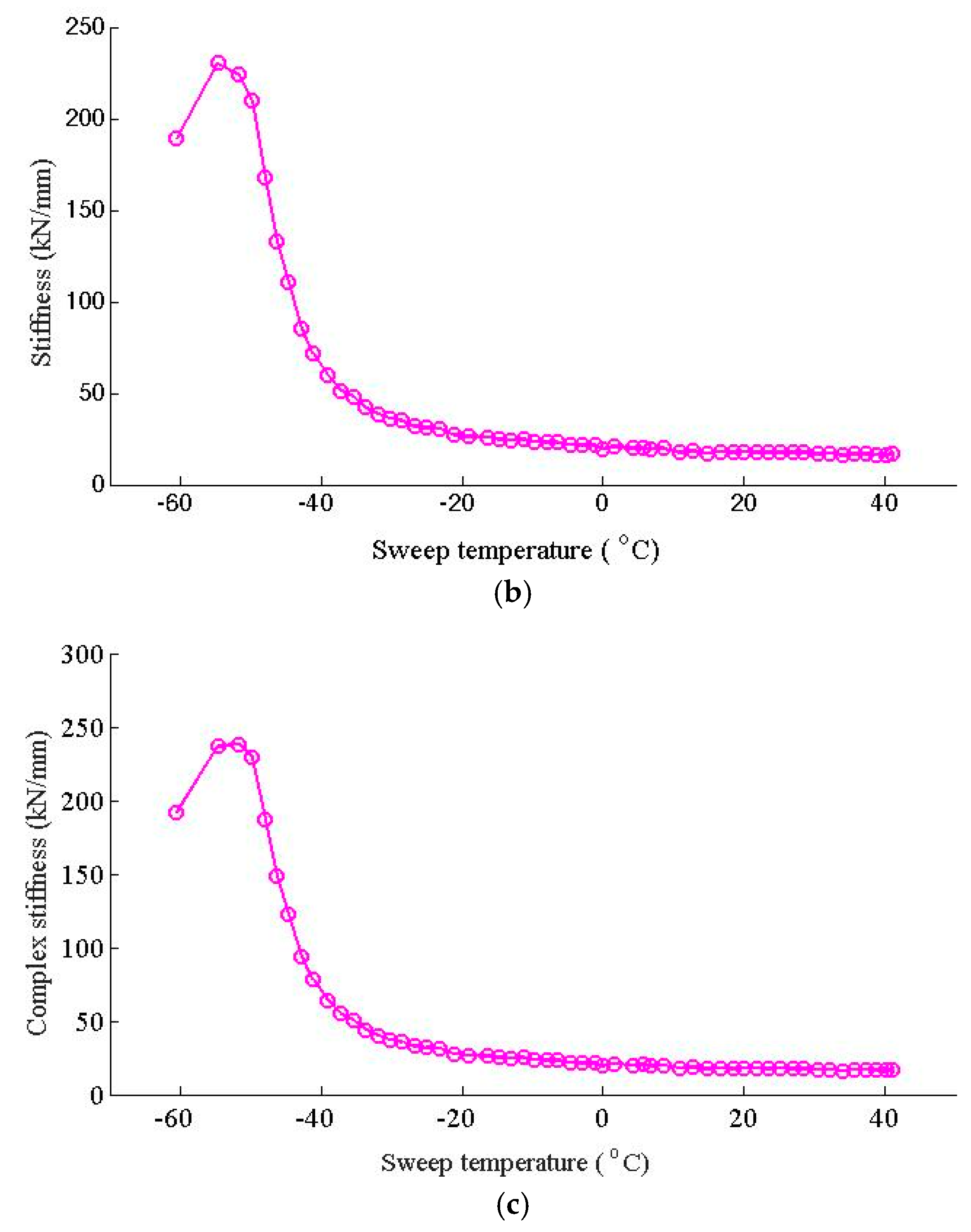
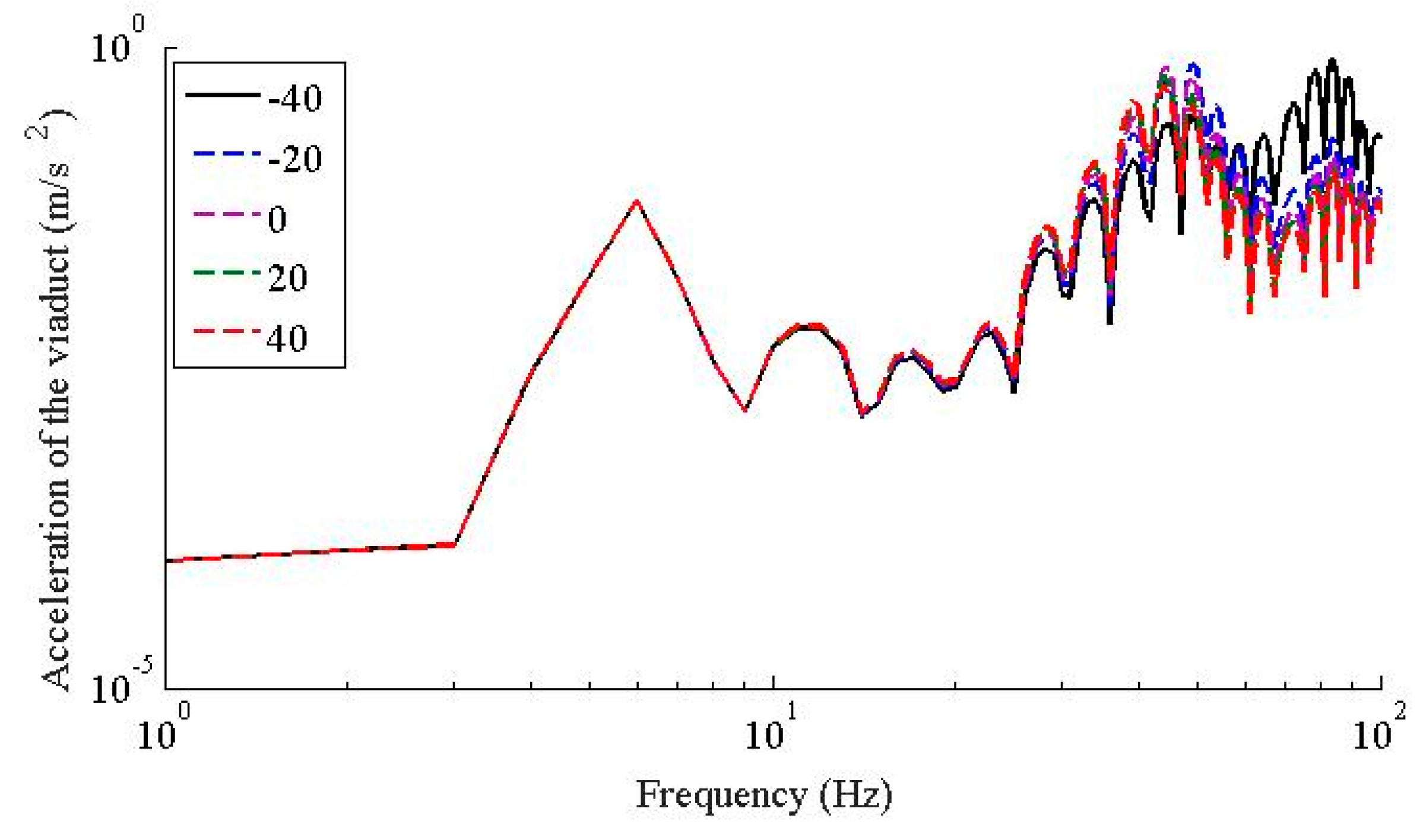
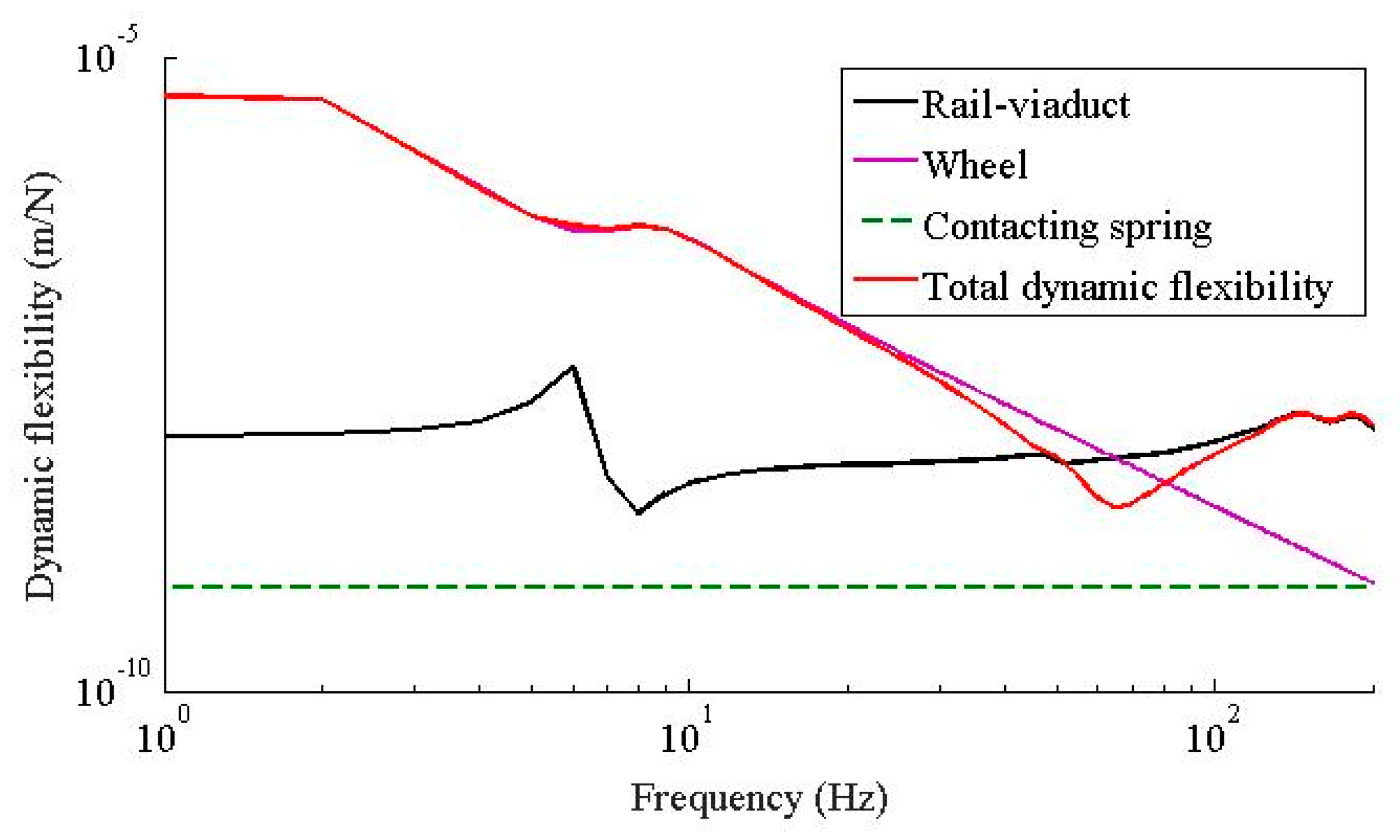
  • The temperature dependent stiffness of the WJ-7B small resistance fastener rubber pad has little effect to the vertical vibration responses of the vehicle; as the temperature increases, the dynamic flexibility of the rail-viaduct increases, the amplitudes increases, but the resonant frequencies decrease especially when the frequency is higher than 30 Hz.
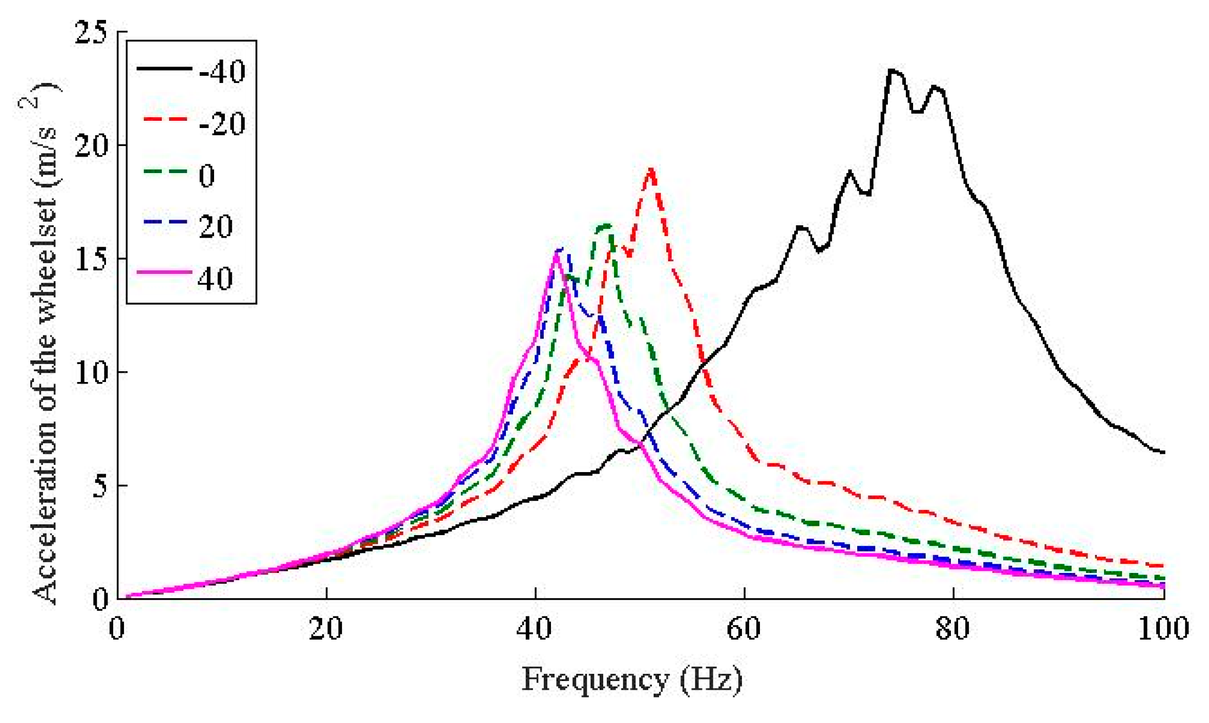
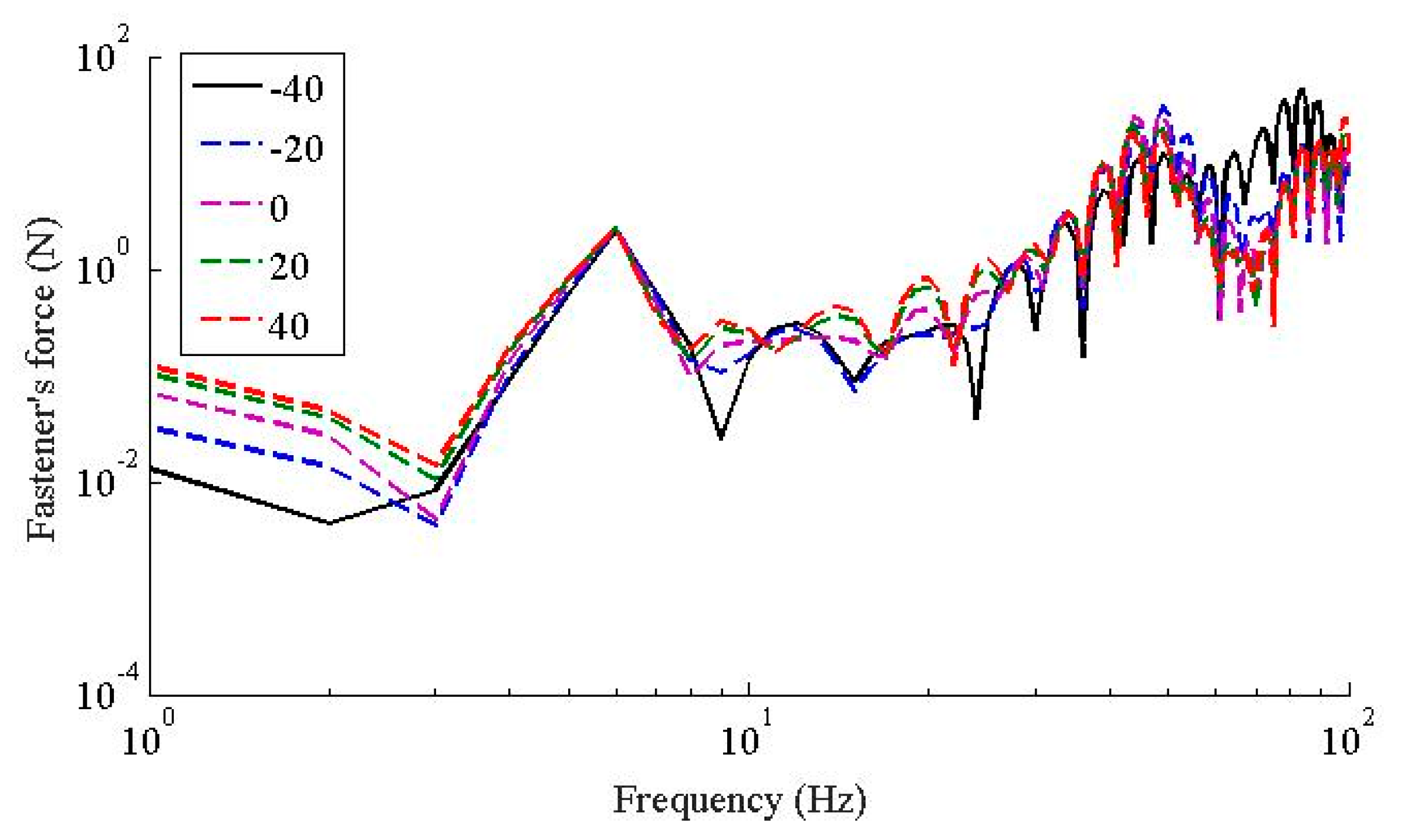
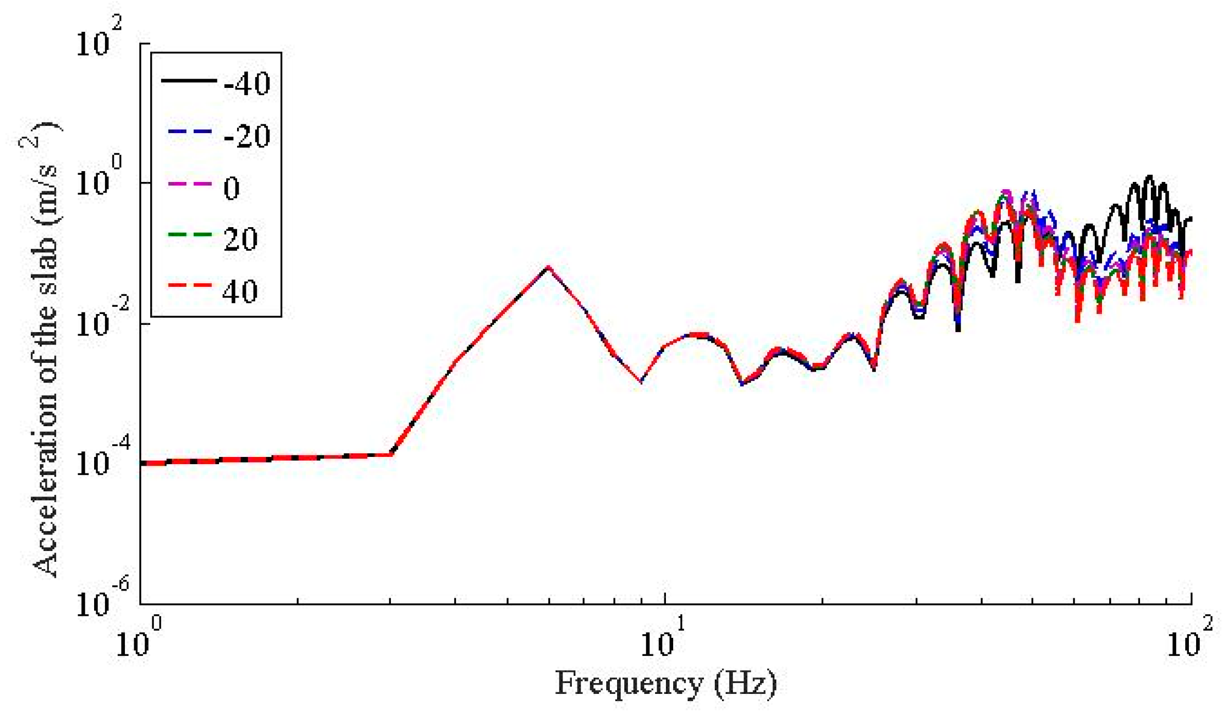
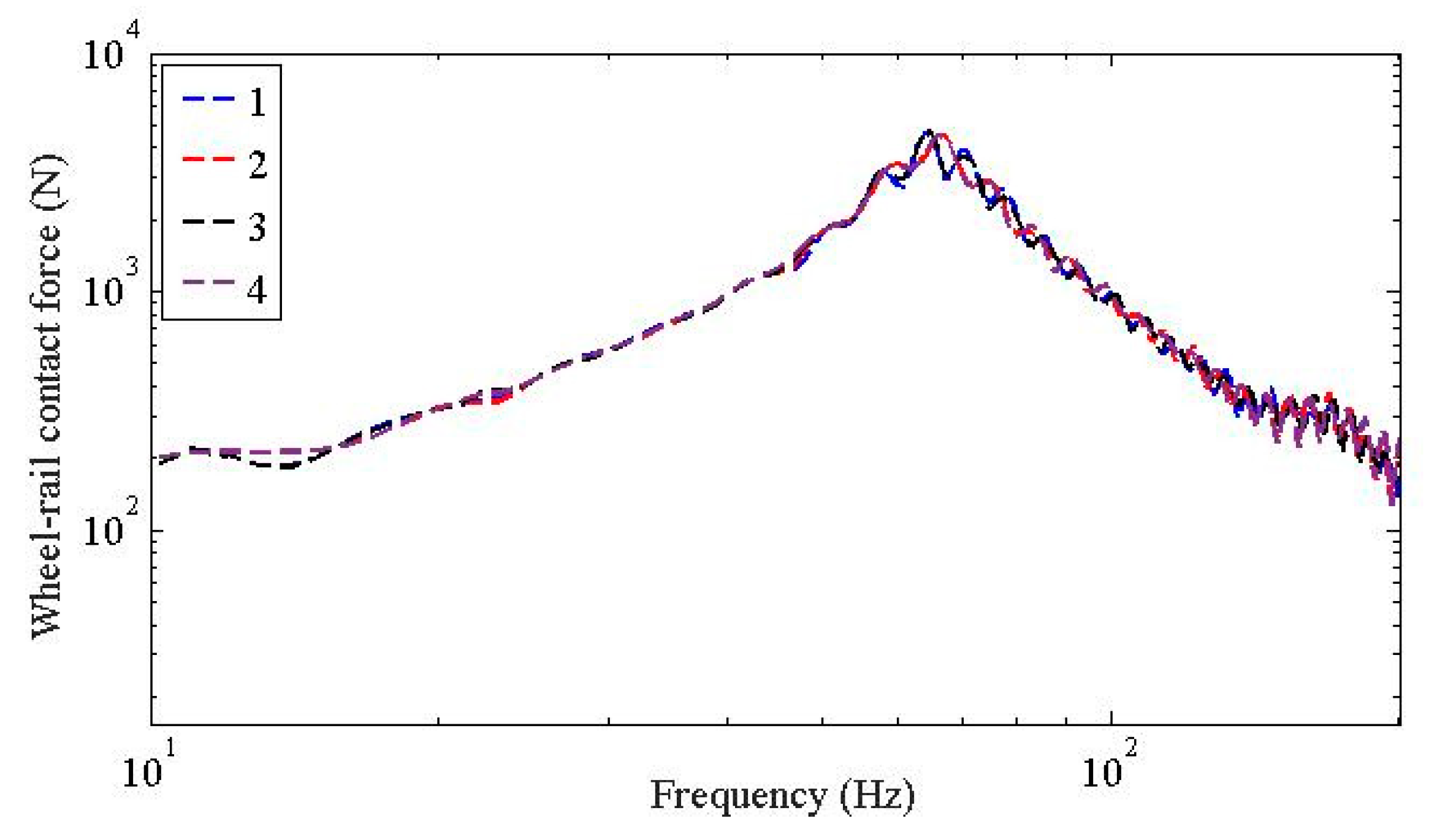
  • In terms of the temperature dependent stiffness to wheel rail force and the dynamic responses of the wheelsets, they share similar characteristics; i.e., in frequency range below 20 Hz, the temperature dependent stiffness of the WJ-7B small resistance fastener rubber pad has little influence on the wheel-rail contact force and the accelerations of the wheelsets; the peaks of the wheel-rail contact force and the accelerations of the wheelsets decrease as the temperature increases, and the dominant frequencies also decrease as the temperature increases; considering the fact that the temperature dependent stiffness of the WJ-7B fastener rubber pad enables the resonant frequencies of the coupled wheel-rail to decrease as the temperature increases, the peak of the acceleration of the viaduct also decreases, and the dominant frequencies shift leftward.
  • In terms of further investigation, the extension of such work to the real engineering tests would be desirable to optimize the proposed methodology. As to engineering application, in the low temperature areas and sudden temperature changing areas, the stiffness of the WJ-7B fastener rubber pad changes sharply, which further affects the vehicle-rail-viaduct coupling analysis. Such an effect has to be considered in certain areas in the engineering projects.

Author Contributions

Conceptualization, L.L. and Y.Z.; methodology, L.L., and Y.Z.; software, Z.Z.; validation, J.Q., and Y.Z.; formal analysis, L.L., and Z.Z.; investigation, Z.Z., and J.Q.; resources, Z.Z.; data curation, J.Q.; writing—original draft preparation, L.L., and Y.Z.; writing—review and editing, Y.Z.; visualization, Y.Z.; supervision, L.L. and Y.Z.; project administration, L.L.; funding acquisition, L.L. All authors have read and agreed to the published version of the manuscript.

Funding

This research was funded by National Natural Science Grant (No. 51578238, 51968025), Jiangxi Province Natural Science Grant for Key Projects (20192ACBL20009), and Jiangxi Province Key Research Program (20181BBE50013).

Conflicts of Interest

The authors declare no conflict of interest.

References

  1. Thompson, D.J.; Verheij, J.W. The dynamic behavior of rail fasteners at high frequencies. Appl. Acoust. 1997, 52, 1–17. [Google Scholar] [CrossRef] [Green Version]
  2. Maes, J.; Sol, H.; Guillaume, P. Measurements of the dynamic railpad properties. J. Sound Vib. 2006, 293, 557–565. [Google Scholar] [CrossRef]
  3. Li, Q.; Wu, D.J. Analysis of the dominant vibration frequencies of rail bridges for structure-born noise using a power flow method. J. Sound Vib. 2013, 300, 4153–4163. [Google Scholar] [CrossRef]
  4. Liu, L.; Qin, J.; Zhou, Y.L.; Xi, R.; Peng, S. Structural noise mitigation for viaduct box girder using acoustic modal contribution analysis. Struct. Eng. Mech. 2019, 72, 421–432. [Google Scholar]
  5. Bezin, Y.; Iwnicki, S.D. An invetigation of sleeper viods using a flexible track model integrated with railway muti-body dynamics. J. Rail Rapid Transit 2009, 223, 597–607. [Google Scholar] [CrossRef]
  6. Zhang, X.; Su, B.; Li, X.Z. Effects of fastener stiffness and damping on structure-borne noise of railway box-girders. J. Vib. Shock 2015, 34, 150–155. [Google Scholar]
  7. Wei, K.; Zhang, P.; Wang, P.; Xiao, J.; Luo, Z. Influence of amplitude-and frequency-dependent stiffness of rail pads on the frequency-domain random vibration of vehicle-track coupled system. Eng. Mech. 2017, 34, 108–115. [Google Scholar]
  8. Liu, Z. Study on the Influence of Amplitude-Dependent and Frequency-Dependent Dynamic Characteristics of Rubber Pads on Wheel-Rail Dynamic Response in High Speed. Ph.D. Thesis, Southwest Jiaotong University, Chengdu, China, 2017. [Google Scholar]
  9. Ahmad, N.; Thompson, D.; Jones, C.; Muhr, A. Predicting the effect of temperature on the performance of elastomer-based rail damping devices. J. Sound Vib. 2009, 322, 674–689. [Google Scholar] [CrossRef]
  10. Zhao, Y.; Hou, Z. Two viscoelastic constitutive models of rubber materials using fractional derivations. J. Tsinghua Univ. 2013, 53, 378–383. [Google Scholar]
  11. Wei, K.; Zhou, C.; Wang, P.; Zhang, P. Influence of Temperature-dependent Stiffness of Rail Pads on the Frequency-domain Random Vibration of Vehicle-track Coupled System. J. China Railw. Soc. 2016, 38, 111–116. [Google Scholar]
  12. Wei, K.; Wang, F.; Zhao, Z.; Hu, X.; Jiang, W. The methodology research on the test and evaluation of static stiffness of elastic pads in elastic separated fastener. J. Railw. Soc. 2018, 35, 32–36+86. [Google Scholar]
  13. Wei, K.; Dou, Y.; Wang, F.; Niu, P.; Wang, P.; Luo, Z. High-frequency random vibration analysis of a high-speed vehicle–track system with the frequency-dependent dynamic properties of rail pads using a hybrid SEM–SM method. Veh. Syst. Dyn. 2018, 1–26. [Google Scholar] [CrossRef]
  14. Liu, L.; Lu, P.; Qin, J. Random Vibration Analysis of Vehicle-track Coupling System Based on Fastener FVMP Model. J. China Railw. Soc. 2019, 41, 93–100. [Google Scholar]
  15. Chang, G. Viscoelastic Damping Materials; National Defense Industry Press: Beijing, China, 2012. [Google Scholar]
  16. Li, L.; Thompson, D.; Xie, Y.; Zhu, Q.; Luo, Y.; Lei, Z. Influence of rail fastener stiffness on railway vehicle interior noise. Appl. Acoust. 2019, 145, 69–81. [Google Scholar] [CrossRef] [Green Version]
  17. Sheng, X.W.; Zheng, W.Q.; Zhu, Z.H.; Luo, T.J.; Zheng, Y.H. Properties of rubber under-ballast mat used as ballastless track isolation layer in high-speed railway. Constr. Build. Mater. 2020, 240, 117822. [Google Scholar] [CrossRef]
  18. Wei, K.; Yang, Q.; Dou, Y.; Wang, F.; Wang, P. Experimental investigation into temperature- and frequency-dependent dynamic properties of high-speed rail pads. Constr. Build. Mater. 2017, 151, 848–858. [Google Scholar] [CrossRef]
  19. Liang, L.; Li, X.; Zheng, J.; Lei, K.; Gou, H. Structure-borne noise from long-span steel truss cable-stayed bridge under damping pad floating slab: Experimental and numerical analysis. Appl. Acoust. 2020, 157, 106988. [Google Scholar] [CrossRef]
  20. Liu, L.; Wang, X.; Zhou, Y.L.; Qin, J. Vibration Mitigation Effect Investigation of a New Slab Track Plate Design. Sensors 2019, 19, 168. [Google Scholar] [CrossRef] [Green Version]
  21. Liu, L.; Song, R.; Zhou, Y.-L.; Qin, J. Noise and Vibration Mitigation Performance of Damping Pad under CRTS-III Ballastless Track in High Speed Rail Viaduct. KSCE J. Civ. Eng. 2019, 23, 3525–3534. [Google Scholar] [CrossRef]
  22. Lei, X. High Speed Railway Track Dynamics: Model, Algorithm and Application; Science Press: Beijing, China, 2015. [Google Scholar]
  23. Shi, G.; Yang, J.; Yang, X.; Zhang, X. Vertical vehicle-track-bridge coupling vibration based on dynamic flexibility method. J. Central South Univ. 2017, 48, 1119–1126. [Google Scholar]
  24. Xin, T.; Zhang, Q.; Gao, L.; Zhao, L.; Qu, J. Dynamic effects and structure optimization of damping layers of CRTSIII slab ballastless track for high speed railway. China Railw. Sci. 2016, 37, 1–7. [Google Scholar]
  25. International Organization for Standardization. ISO 3095:2005: Railway Applications-Acoustics-Measurement of Noise Emitted by Rail Bound Vehicles. 2005. Available online: https://www.iso.org/standard/41669.html (accessed on 10 March 2020).
  26. Zhang, Z. Semi-analytical analysis and experimental study of ground vibration induced by trains moving over high-speed railway bridges. Ph.D. Thesis, Southwest Jiaotong University, Chengdu, China, 2016. (In Chinese). [Google Scholar]
Figure 1. Details of the fastener rubber pad: (a) Fastener rubber pad of one fastener type; (b) Fastener rubber pad of another fastener type.
Applsci 10 01889 g001
Figure 2. Vertical model of vehicle-track coupling system: (a) high-speed railway (HSR) system; (b) vehicle-rail-viaduct coupled model.
Applsci 10 01889 g002
Figure 3. Flowchart for the vehicle-rail-slab coupled system dynamic analysis.
Applsci 10 01889 g003
Figure 4. A typical WJ-7 small resistance fastener system.
Applsci 10 01889 g004
Figure 5. WJ-7B small resistance fastener rubber pad specimen and test equipment.
Applsci 10 01889 g005
Figure 6. Mechanical parameters of WJ-7B small resistance fastener rubber pad: (a) Young’s modulus, (b) stiffness, (c) complex stiffness.
Applsci 10 01889 g006aApplsci 10 01889 g006b
Figure 7. Dynamic flexibility amplitude of the rail under −40, −20, 0, 20, and 40 °C.
Applsci 10 01889 g007
Figure 8. Wheel-rail contact force under −40, −20, 0, 20, and 40 °C.
Applsci 10 01889 g008
Figure 9. Vertical acceleration of vehicle under −40, −20, 0, 20, and 40 °C.
Applsci 10 01889 g009
Figure 10. Vertical acceleration of the wheelset under −40, −20, 0, 20, and 40 °C.
Applsci 10 01889 g010
Figure 11. The WJ-7B small resistance fastener’s force under −40, −20, 0, 20, and 40 °C.
Applsci 10 01889 g011
Figure 12. Vertical acceleration of the rail under −40, −20, 0, 20, and 40 °C.
Applsci 10 01889 g012
Figure 13. Vertical acceleration of the track slab under −40, −20, 0, 20, and 40 °C.
Applsci 10 01889 g013
Figure 14. Vertical acceleration of viaduct under −40, −20, 0, 20, and 40 °C.
Applsci 10 01889 g014
Figure 15. Simple diagram for the three-span bridge with piers.
Applsci 10 01889 g015
Figure 16. Wheel-rail contact force for wheel 1, 2, 3, and 4.
Applsci 10 01889 g016
Figure 17. Multiple-layer model for the vehicle-rail-viaduct system.
Applsci 10 01889 g017
Figure 18. Dynamic flexibility of the vehicle-rail-viaduct system.
Applsci 10 01889 g018
Figure 19. Phase of the dynamic flexibility of the vehicle-rail-viaduct system.
Applsci 10 01889 g019
Table 1. Analytical scenarios of WJ-7B small resistance.
CasesTemperature (°C)Stiffness (MN/m)
#1−4064.71
#2−2026.66
#3021.00
#42017.94
#54016.65
Table 2. Model parameters of CRH380A high-speed train.
Parameter, Symbol (Unit)Value
Vehicle’s weight under rated load (kg)42,934
Bogie weight (kg)3300
Wheelset weight (kg)1780
Rotary of inertia for vehicle’s nod (kg m2)1.712 × 10⁶
Rotary of inertia for bogie’s nod (kg m2)1807
Vertical stiffness of primary suspension (N m−1)1.176 × 10⁶
Damping of primary suspension (N s/m)1.0 × 104
Stiffness of secondary suspension (N m−1)2.4 × 10⁵
Damping of secondary suspension (N s/m)2.0 × 104
Length of train (m)25
Fixed distance of carriage (m)17.5
Fixed distance between axles (m)2.5
Table 3. Dynamic parameters of the slab-rail-viaduct system.
ComponentSymbol, UnitValue
RailStiffness (N/m2)2.059 × 1011
Sectional inertia moment (m4)3.217 × 10⁻⁵
Density (kg/m3)7850
Section area (m2)7.745 × 10⁻³
Shear modulus (N/m2)7.7 × 1010
Section coefficient (κ)0.45
Loss factor (ηr)0.01
FastenerLoss factor0.25
Distance between fasteners (m)0.625
SlabStiffness (N/m2)3.6 × 1010
Sectional inertia moment (m4)1.7 × 10⁻³
Density (kg/m3)2750
Section area (m2)0.51
Loss factor0.1
CA mortarEquivalent stiffness (N/m)0.78 × 109
Loss factor0.2
ViaductLength (m)32
Stiffness (N/m2)3.45 × 1010
Sectional inertia moment (m4)5.757
Density (kg/m3)2650
Section area (m2)4.416
Loss factor0.1
Bearing for the viaductStiffness (MN/m)6 × 109
Distance between bearings (m)32
Loss factor0.25
Table 4. The first order and dominant resonant frequencies comparison for five scenarios in the dynamic flexibility amplitude of the rail.
ScenariosFirst Order and Dominant Resonant Frequencies
First Order Resonant FrequencyDominant Resonant Frequency
(Hz)∆(#-#1) (Hz)∆(#1-#) (%)(Hz)∆(#-#1) (Hz)∆(#1-#) (%)
#160014200
#25116.67130128.45
#35116.671182416.90
#45116.671103222.53
#55116.671073524.65
Table 5. The peak value and dominant frequency from the vertical acceleration of the wheelset.
ScenariosPeak Value and Dominant Frequency
Peak ValueDominant Frequency
(kN)∆(#1-#) (%)(Hz)∆(#1-#) (%)
#120.620740
#216.7918.575131.08
#314.4130.124736.49
#413.5034.534341.89
#513.3535.264243.24

