Article

Numerical-Experimental Investigation into the Tensile Behavior of a Hybrid Metallic–CFRP Stiffened Aeronautical Panel

1
Department of Engineering, University of Campania “Luigi Vanvitelli”, via Roma 29, 81031 Aversa, Italy
2
Leonardo Company SpA, Via dell’Aeronautica, 80038 Pomigliano d’Arco, Italy
*
Author to whom correspondence should be addressed.
Appl. Sci. 2020, 10(5), 1880; https://doi.org/10.3390/app10051880
Submission received: 20 February 2020 / Revised: 27 February 2020 / Accepted: 5 March 2020 / Published: 10 March 2020
(This article belongs to the Special Issue Progress of Fiber-Reinforced Composites: Design and Applications)

Abstract

:
In this work, the tensile behavior of a hybrid metallic–composite stiffened panel is investigated. The analyzed structure consists of an omega-reinforced composite fiber-reinforced plastic (CFRP) panel joined with a Z-reinforced aluminum plate by fasteners. The introduced numerical model, able to simulate geometrical and material non-linearities, has been preliminary validated by means of comparisons with experimental test results, in terms of strain distributions in both composite and metallic sub-components. Subsequently, the inter-laminar damage behavior of the investigated hybrid structure has been studied numerically by assessing the influence of key structural subcomponents on the damage evolution of an artificial initial debonding between the composite skin and stringers.

1. Introduction

In recent years, the use of composite fiber-reinforced plastic (CFRP) for the manufacturing of aerospace primary structures has unquestionably increased. However, despite the undeniable advantages in terms of weight related to composites, metal parts are still widely used because of the criticalities related to the damage management of the new outstanding composites [1,2,3,4,5,6]. Therefore, for several structural components, metal/composite hybrid solutions are adopted, due to the effective reduction in weight and costs without strong compromises in terms of safety [7,8].
In the literature, the damage behavior of composite materials has been widely investigated, pointing out the effects in terms of induced damage of impacts with foreign objects [9,10,11,12,13,14], of the manufacturing or the assembly processes [15,16,17,18] and, finally, the effects of service loading conditions.
Indeed, in order to exploit the advantages related to the adoption of composite–metal hybrid solutions, it is mandatory to understand the issues related to the manufacturing and the joining of these different materials [19].
In [20], a comprehensive review on the methods, commonly adopted, to join CFRP and aluminum alloys parts was presented. Among the several methods described, adhesive joints, bolts, and self-piercing rivets (SPR) are, of course, the most affordable. In particular, bonded joints have been found to be the method most adopted to join CFRPs and aluminum alloys parts. Indeed, bonded joints avoid undesirable stress concentrations and does not require an intrusive application, being at the same time weight saving with respect to other joining techniques. However, since the bonding is an irreversible process, the separation of joined components often results in critical material damage, as demonstrated by several investigations on bonded joints found in the literature [21,22,23,24,25]. A CFRP/aluminum double lap-bonded joint was presented in [26] where a non-linear cohesive material model was used to investigate the bonded interface behavior. In [27], the strain distribution in CFRP/aluminum double lap joints was experimentally and numerically investigated. The surface strain within the adhesive layer was measured by using high-magnification Moiré interferometry. Hence, the spatial variation of longitudinal, peel, and shear strains was evaluated in detail and compared to numerical predictions.
Moreover, due to the different thermal expansion coefficients of metal and composite sub-components, the effects of the thermal residual stress in terms of curvature of the composite/metal assembly should be addressed. This issue was investigated in [28], where a thermo-chemical-mechanical constitutive model was used to simulate the curing process of the composites and to evaluate the thermal residual stresses of a metal/CFRP plate. In [29], the mode I and II interfacial fracture behavior of a titanium/CFRP bonded joint was studied by considering the bending-extension coupling induced by the presence of the aluminum beams and the manufacturing-induced residual thermal stresses.
Bolts and rivets are a common alternative to bonded joints [30,31,32,33,34,35]. The bolt is inserted in a uniaxial common hole in components to be joined. However, the hole drilling may generate damage and defects in the CFRP components, which can evolve due to the service load, affecting the life of the components themselves. In [36], an experimental study on the manufacturing defects induced by drilling aluminum/CFRP stacks was performed, aimed to determine the critical geometric parameters of a carbide drill in order to reduce the fragmentation of the metallic chips while avoiding damages on the composite components. This issue was also addressed in [37], where nano-coated carbide drills were used to reduce the damages resulting in drilling multimaterials made of aluminum alloy and CFRP.
Additionally, a numerical and experimental investigation on the mechanical behavior of CFRP/aluminum bolted joints was introduced in [38], focusing on the effect of the environmental conditions (temperature and moisture) on the mechanical performances of the bolted joint. Hence, different tests were presented by considering extremely hot, hot and humid, and extremely cold environmental conditions.
In [39], the thermal effects on a single lap hybrid metal/composite bolted joint were investigated. Indeed, metal and CFRP are characterized by different thermal expansion coefficients, resulting in uneven load-deformation characteristics and three-dimensional stress field around the bolt hole.
The self-piercing rivet technique is used to join sheet materials [40,41]. Unlike bolted joints, this method does not require a pre-drilled hole, allowing faster joining performed in just one operation. However, this operation has a critical impact on the fatigue life and on the static strength of hybrid CFRP/aluminum components [41,42,43]. In particular, in [44] the possible damage induced by self-pierce riveting of CFRP with aluminum, which include delamination and fiber/matrix failures in the CFRP region, were investigated, and the influence of the damage on the joint strength was assessed. In [45], the tensile and fatigue properties of CFRP/aluminum self-pierce riveting joints were evaluated. Different joint configurations were investigated, and the influence of the rivets’ geometrical parameters on the joint failure was studied.
In general, the choice of the particular joining technique strongly depends on the specific application. In order to take advantage of the benefits of the different joining techniques, hybrid solutions can be found whose performance is enhanced by combining adhesives with rivets or bolts [46,47,48,49]. In [50], an experimental investigation on single-lap joined CFRP laminate and AA2024-T6 aluminum sheet was introduced. Bonded, self-pierce riveting, and hybrid SPR/bonded joints were considered. In particular, an appreciable synergism of the bonded and self-pierce riveting joints could be observed in the hybrid solution, which exploited high resistance levels due to the bonding and the high failure energy due to the self-pierce riveting. In [51], a semi-analytical method was developed for the analysis of composite bolted/bonded single lap joints, under coupled in-plane and bending loads. The method was based on Mindlin and Timoshenko beam theories to evaluate the laminate and the bolt displacements, respectively. Several test cases were introduced, including analyses of bolted joints, bonded joints, and hybrid joints. Additional analyses were carried out for the hybrid configuration, considering a debonding in the bonded interface between the laminates.
A few works can be found in the literature on the mechanical behavior, including damage, of hybrid composite–metal structures, composed of differently joined subcomponents. An investigation on a complex bolted structure can be found in [52], where the mechanical behavior of a hybrid composite/aluminum wing-box was assessed. The structure was composed of a number of single-lap bolted joints with a titanium fastener, which were numerically studied by introducing a three-dimensional finite element model (FEM), able to account for material non-linearity such as progressive damage, and plasticity models, respectively, in the composite and metal regions. Two-node connector elements were used to simulate the fasteners behavior. Both twisting and bending loading conditions were considered, together with an applied increased temperature, in order to locally investigate the behavior of the bolted joints. Experimental results were used to validate the numerical model.
However, more investigations are mandatory to fully understand the effect of the joints on the mechanical behavior of a complex structure composed of different subcomponents, as well as the effects of key structural components on the damage behavior of hybrid complex structures.
Hence, in this work the mechanical behavior, including damage onset and evolution, of a tensile loaded hybrid composite/metal panel, is investigated. The investigated structure consists of an omega-reinforced carbon fiber-reinforced plastic (CFRP) panel joined with a Z-reinforced metal plate by fasteners. Numerical models have been introduced, able to take into account the geometrical and material non-linearity related to large displacements and deformations, such as the plasticity on the metal region and the intra-laminar damage on the composite components [53,54,55]. The introduced numerical models, based, respectively, on tie and fastener formulation to connect the sub-components, have been validated by means of comparisons with data, in terms of strain distribution on both composite and metallic regions, from an experimental tensile test. Finally, the stringer termination debonding has been investigated, by assessing the influence of key structural components on the inter-laminar damage behavior [56,57] of the hybrid structure. In Section 2, the analyzed test case is defined. In Section 3, the experimental setup is briefly described, while in Section 4 the numerical models are introduced. The numerical and experimental results are presented and critically analyzed in Section 5, while the stringer termination debonding is introduced and discussed in Section 6.

2. Test Case Description

The investigated structure consisted of a hybrid composite-metal reinforced panel. According to Figure 1, different regions can be identified. The first metal region consisted of an aluminum plate reinforced with Z-stringers, while the composite region consisted of a plate reinforced with omega stringers. A second metal region was placed between the plate. All the components were connected by means of fasteners. The hybrid structure was loaded in tension, up to 300 kN, by clamping one edge while applying an imposed tensile displacement on the opposite side. In Figure 1, the geometrical description of the structure, including the different materials regions and the boundary conditions, is reported, while in Figure 2 some views of the geometrical model are shown.
Three different material systems were adopted to manufacture the panel: AA 2024 and AA 7075 (metal regions), and IMS/977-2 (CFRP region). The mechanical properties of the involved material systems are presented in Table 1 and Table 2. In particular, Table 2 reports the mechanical properties of the IMS/977-2 material system including elastic properties, inter-laminar critical values (evaluated by means of the double cantilever beam and end notched flexure tests), and inter-laminar critical values.
The thickness of each IMS 977-2 ply was 0.188 mm. The number of plies of the composite skin and of the stringers ranged gradually from 8 to 16. The number of plies and the corresponding stacking sequences are reported in detail in Figure 3 and Figure 4 for the skin and the stringers, respectively.

3. The Experimental Setup

Fourteen strain gauges were placed along the loading direction to monitor the deformations on the hybrid panel. The locations of the strain gauges are shown in Figure 5.
Indeed, four strain gauges were placed on the composite stringers (SG1, SG2, SG5, and SG6), five strain gauges were placed on the composite panel (SG3, SG4, SG7, SG8, and SG9), and the last five strain gauges were placed on the metal panel (SG10, SG11, SG12, SG13, and SG14).
Figure 6 shows a picture of the hybrid panel including the fixtures used for clamping the panel to the test rig to perform the tensile test. The undergoing experimental test is shown in Figure 7.

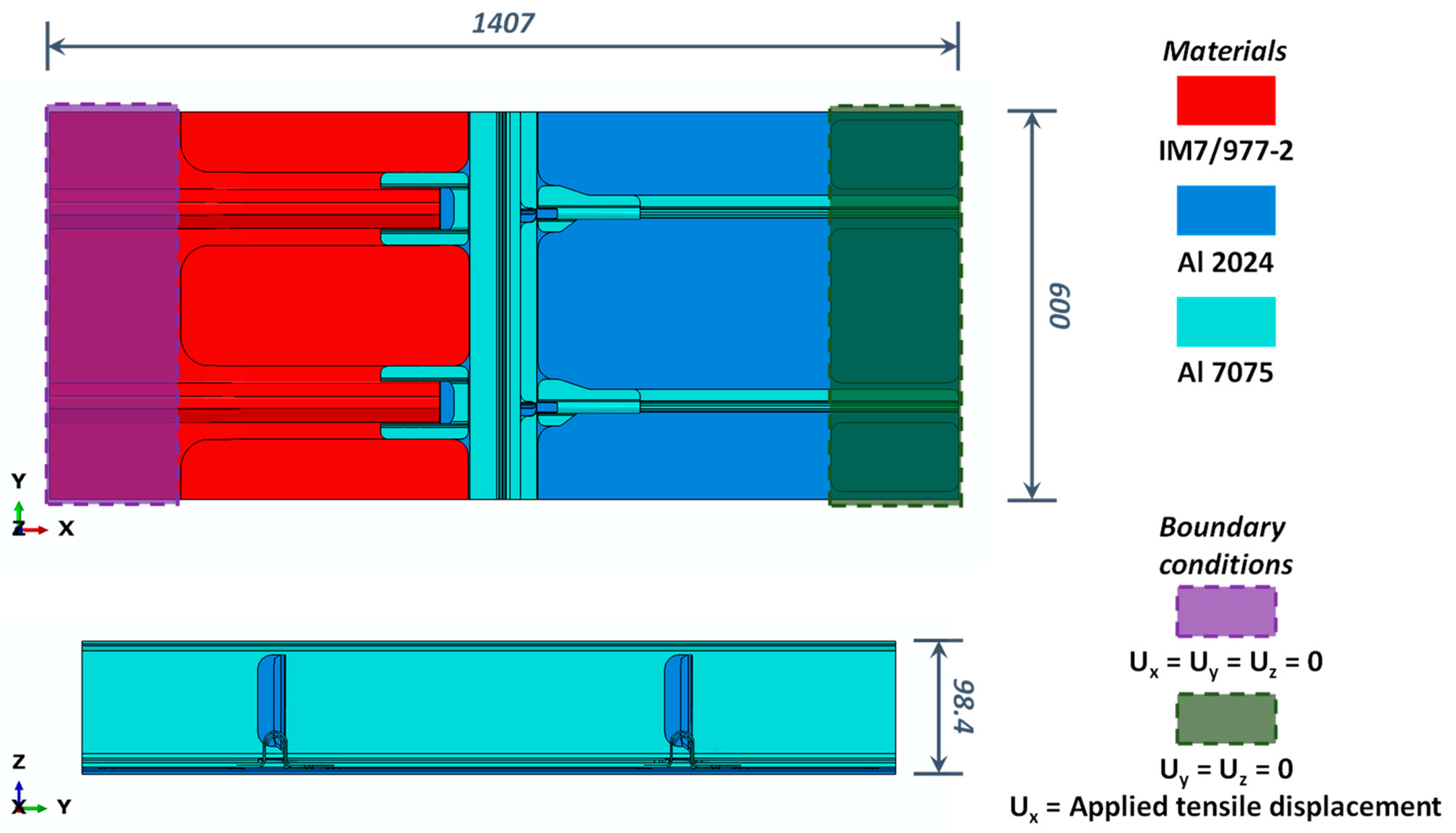
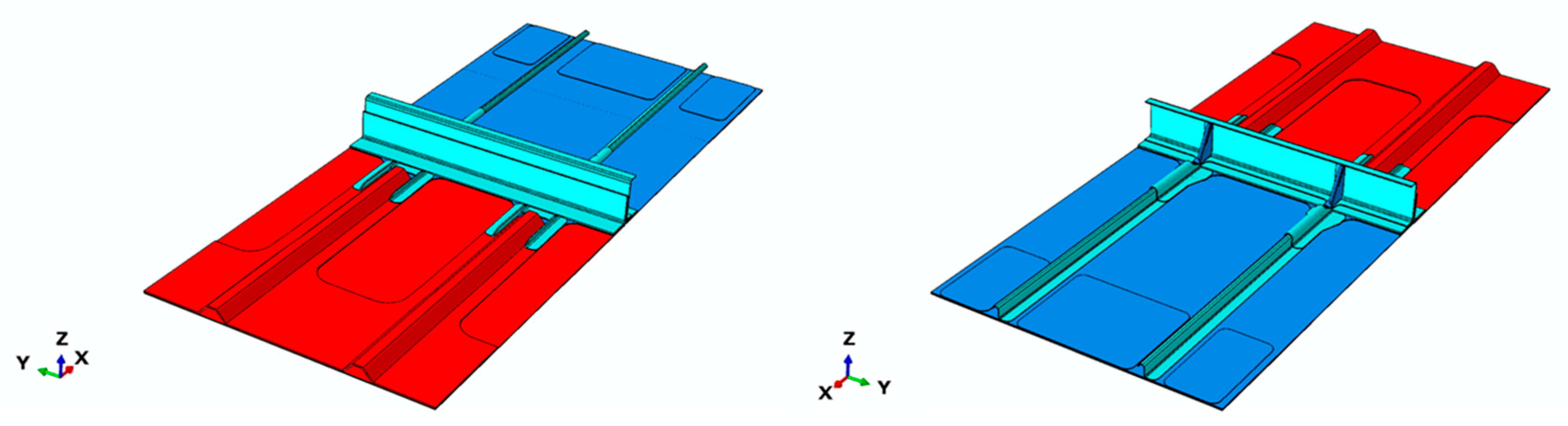
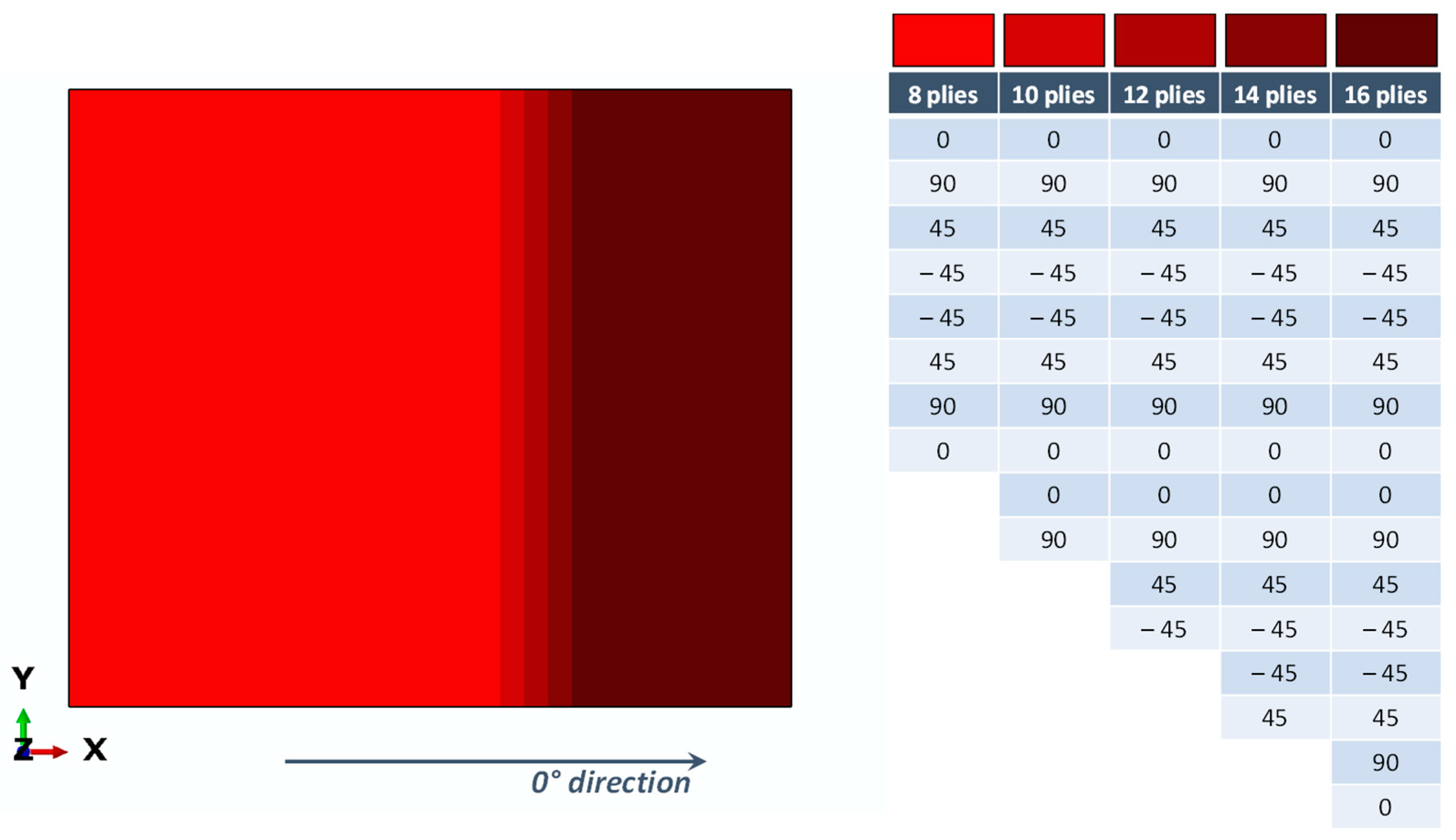
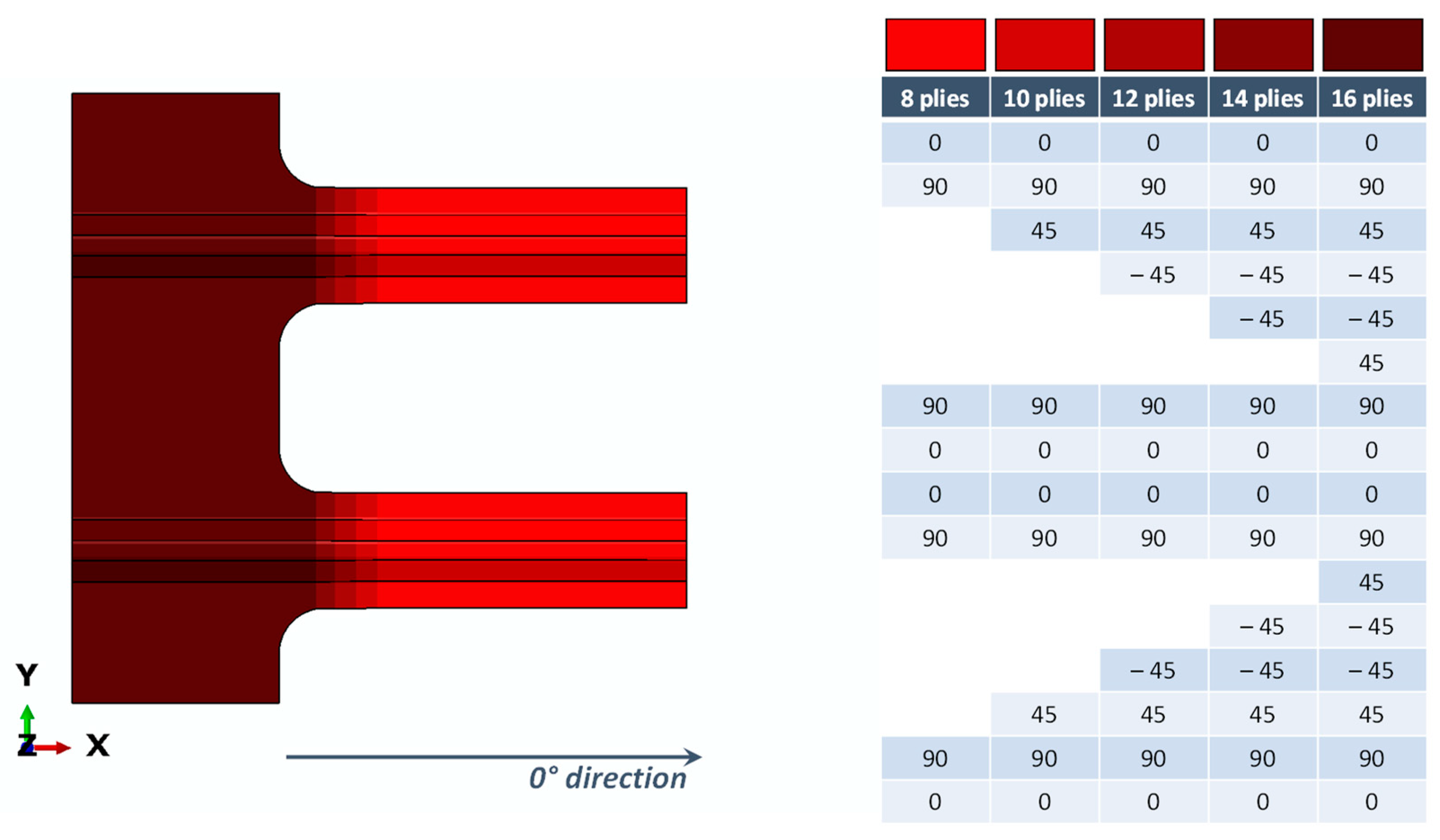
4. The Numerical Model

Numerical simulations were carried out within the ABAQUS (Finite Element) FE environment. The composite region was discretized by means of 28,348 continuum shell elements with a reduced integration scheme (SC8R), while 27,468 solid elements with a reduced integration scheme (C3D8R) were used to model the metallic components. The mesh size was chosen based on a preliminary mesh sensitivity analysis, which is not reported here for the sake of brevity. Figure 8 shows the finite element model, highlighting the connections among the different sub-components.
The damage onset and evolution were considered in the frame of the preformed tensile analyses. In particular, the Hashin’s limit failure criteria was used to simulate the damage in the composite sub-components, since they consider the interaction between the stresses acting on each lamina, distinguishing the failure mechanisms associated to both fibre and matrix failures due to tensile and compressive loads [59]. Moreover, a bilinear plasticity model was considered for the metallic sub-components.
According to Hashin’s limit failure approach, separate criteria were introduced by Equations (1)–(4) to determine the damage status within the material:
F f t = ( σ 11 X T ) 2 + α ( σ 12 S L ) 2 = 1           if           σ 11 > 0
F f c = ( σ 11 X C ) 2 = 1           if           σ 11 < 0
F m t = ( σ 22 Y T ) 2 + ( σ 12 S L ) 2 = 1           if           σ 22 > 0
F m c = ( σ 22 2 S T ) 2 + [ ( Y C 2 S T ) 2 1 ] ( σ 22 Y C ) 2 + ( σ 12 S L ) 2 = 1           if           σ 22 < 0
In more detail, Equations (1)–(4), associated respectively to fibre failure in tension and compression and matrix failure in tension and compression, are expressed as a function of the fibre tensile (XT) and compressive (XC) strength, of the matrix tensile (YT) and compressive (YC) strengths, and of the transversal (ST) and longitudinal (SL) shear strengths. Once the Hashin’s limit values have been reached, the material can be considered damaged, and the stiffness is gradually reduced by a coefficient d, defined for each failure mode, ranging from 0 (undamaged condition) to 1 (completely damaged condition).
For metallic sub-components, according to the introduced bilinear plastic model schematically represented in Figure 9, when stresses overcome the yield threshold, the resulting deformation εtot can be expressed as the sum of an elastic contribution εel (evaluated as the ratio between the applied stress σ and the elastic modulus E; εel = σ/E) and a plastic contribution εp.
ABAQUS TIE multipoint constraints were used to model the bonded connection between sub-components, as shown in Figure 10. These connections involved the composite skin and the composite omega stringers, the metal skin and the doubler, and the metal skin and the fillers.
To numerically reproduce the fastener behaviour in fastened connections, two approaches were used:
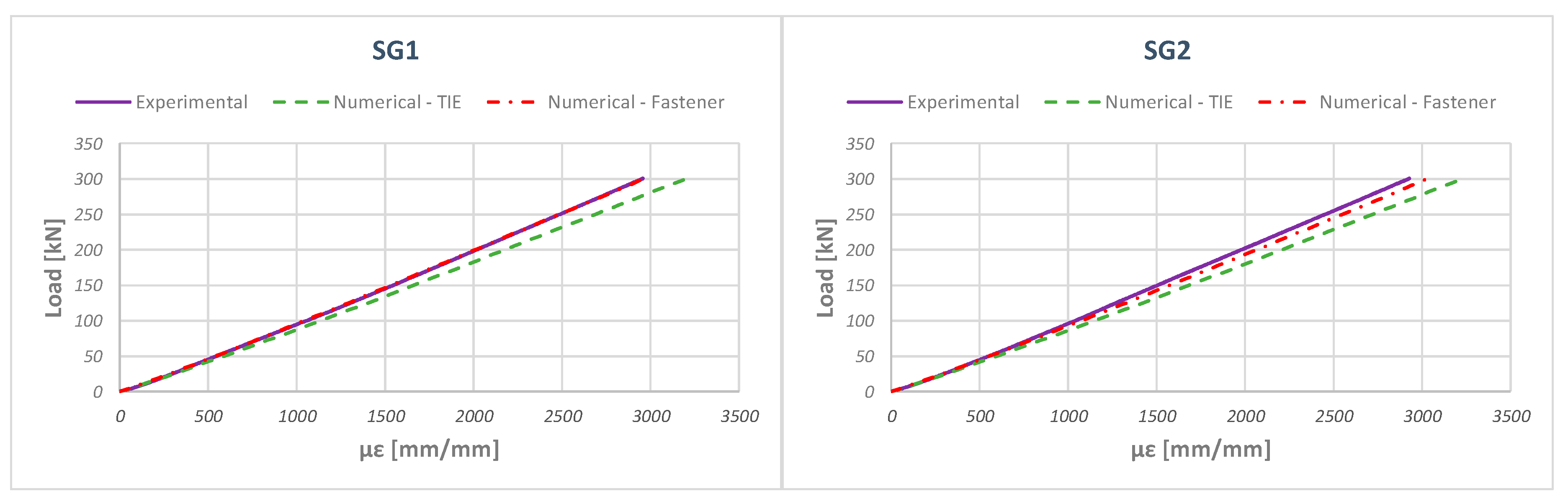
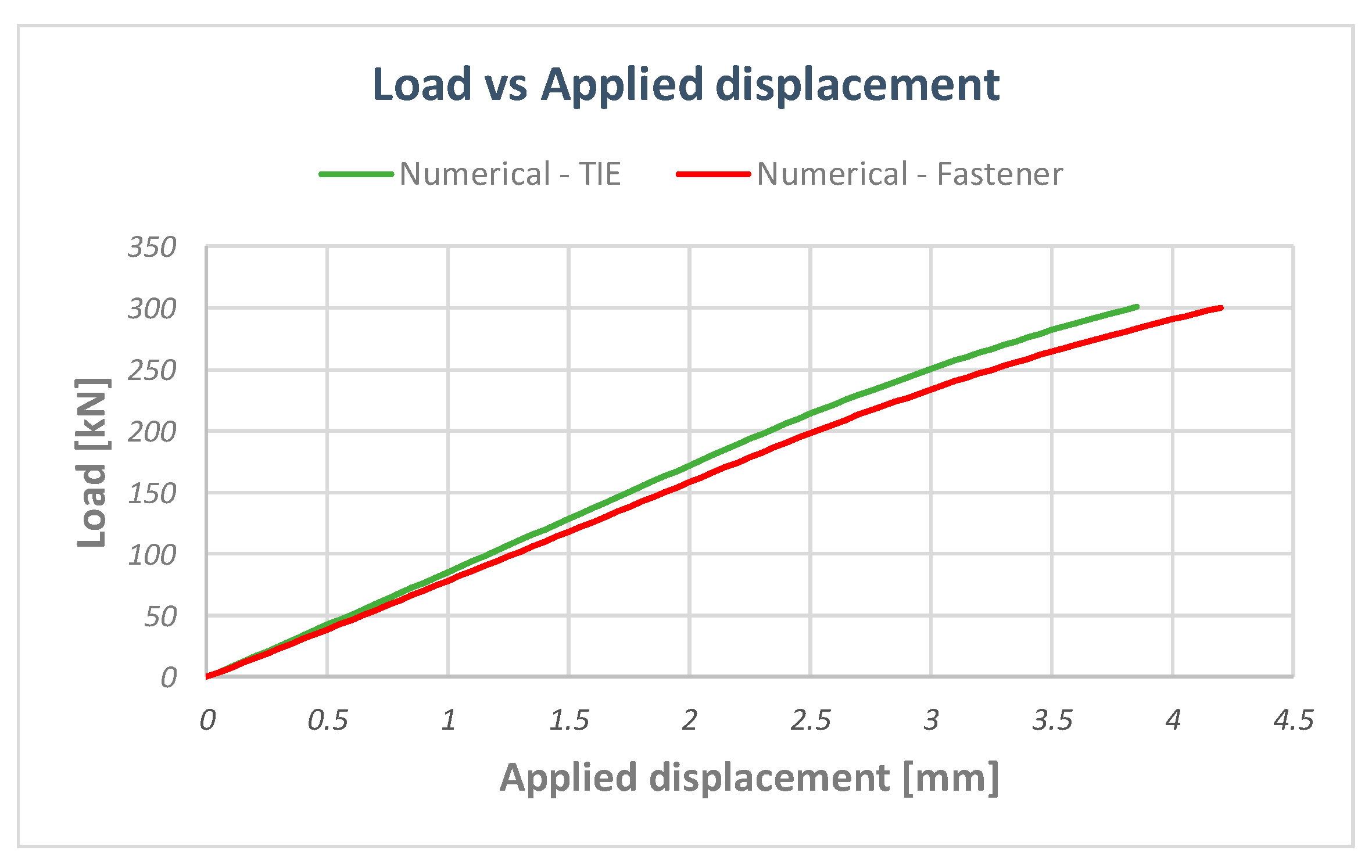
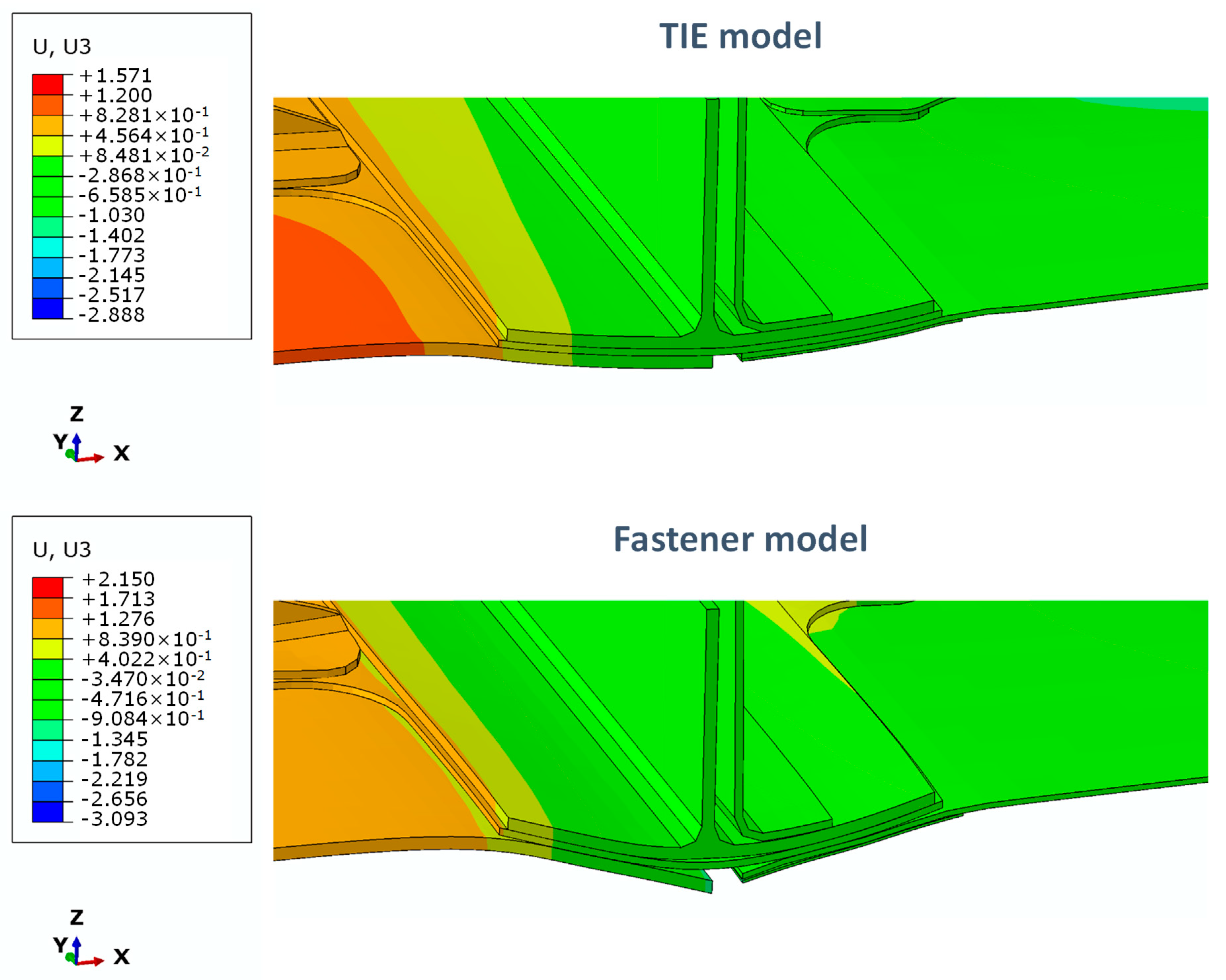
  • Model with Tie: TIE constraints: this was used to connect the surfaces of the fastened subcomponents;
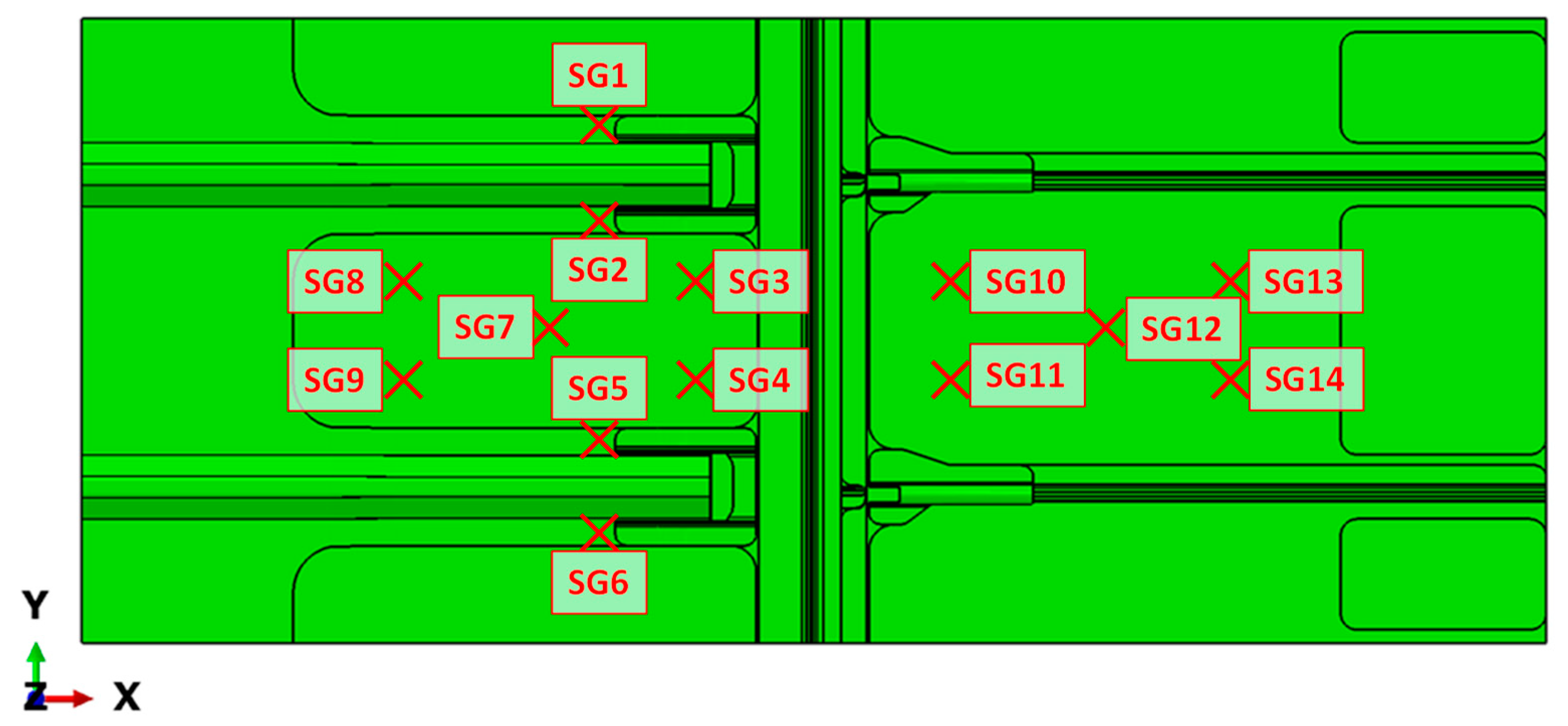
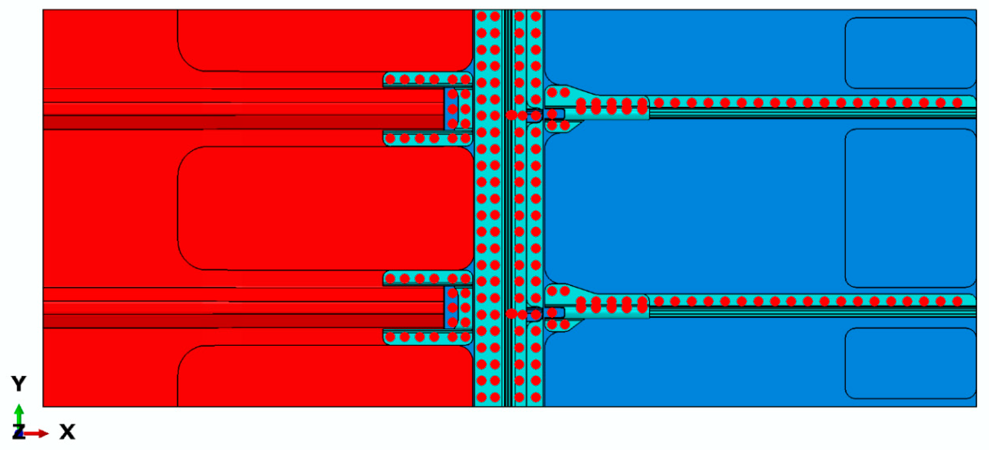
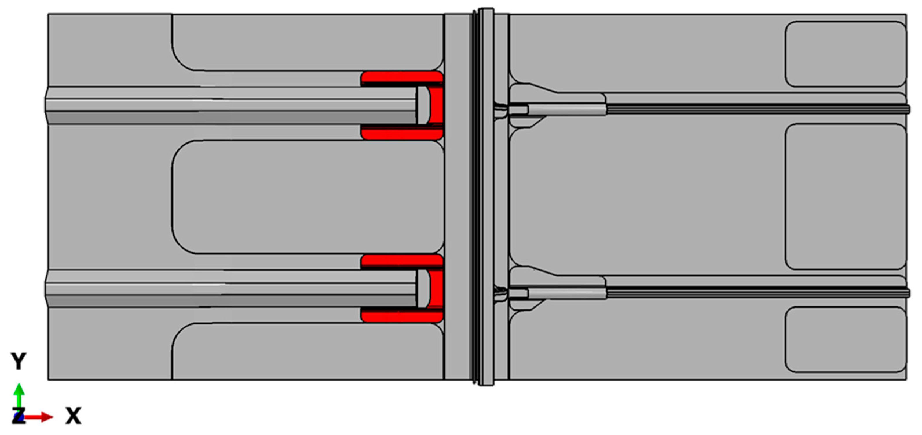
  • Model with Fastener: the fasteners were numerically simulated by means of ABAQUS fastener connectors. An elastic behaviour was supposed for the fastener connectors, which were placed in the locations of the experimental test-case, reported in Figure 11.

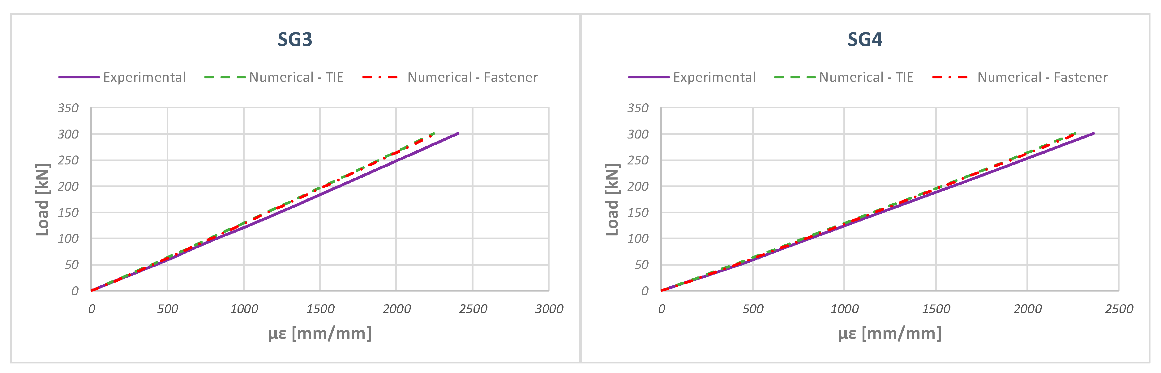
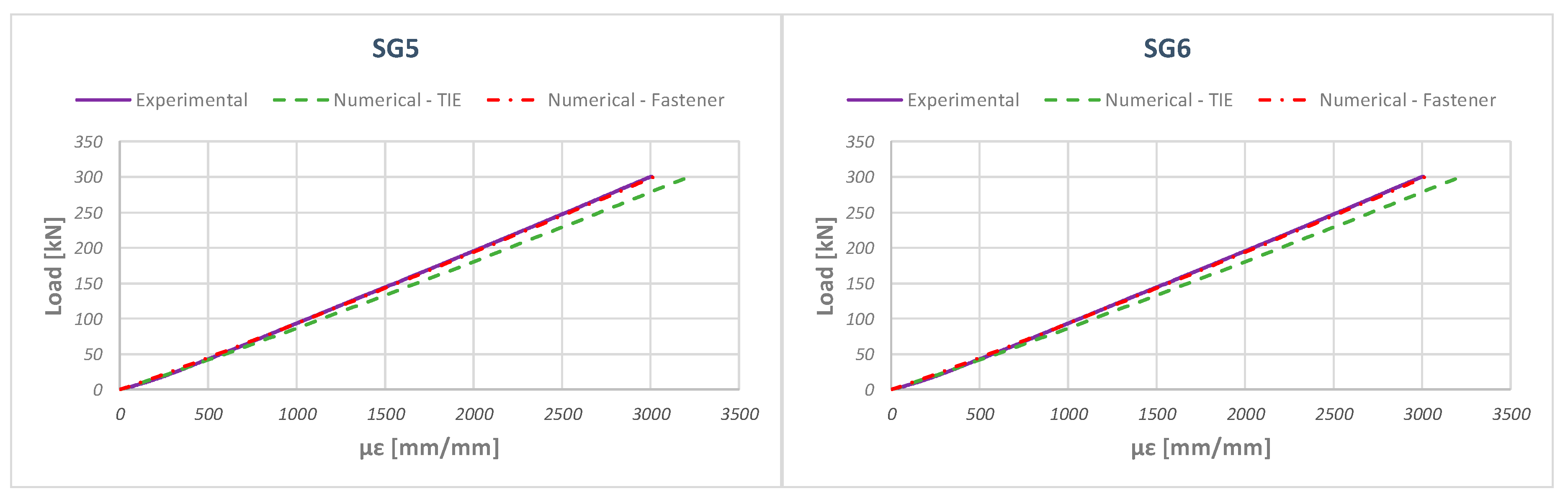
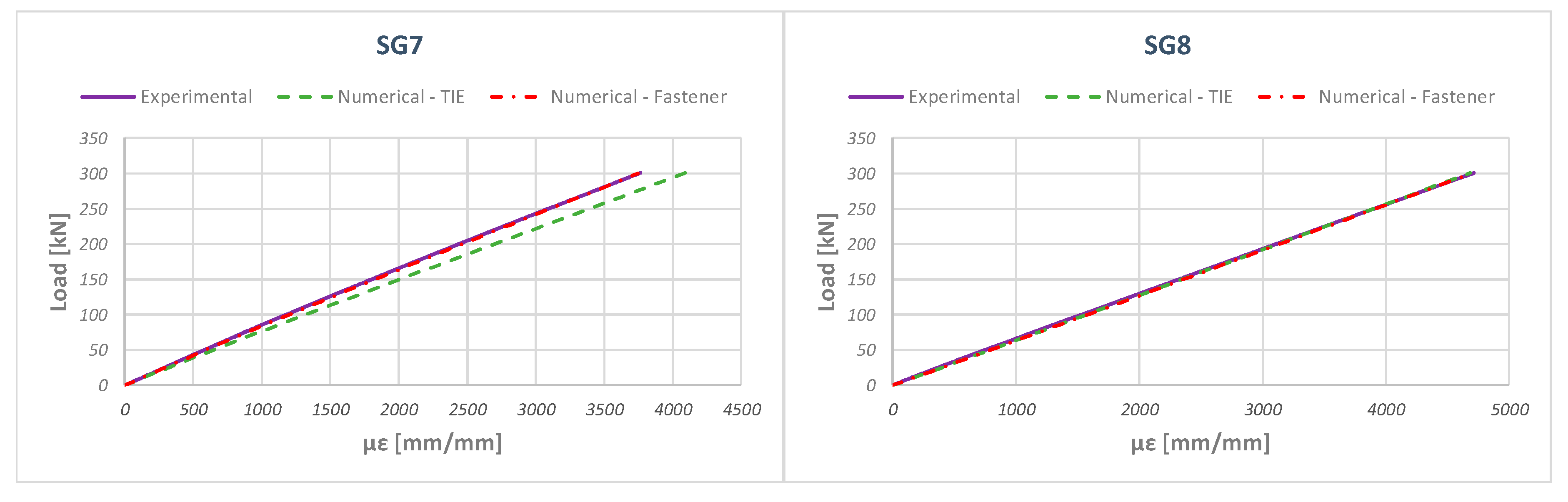
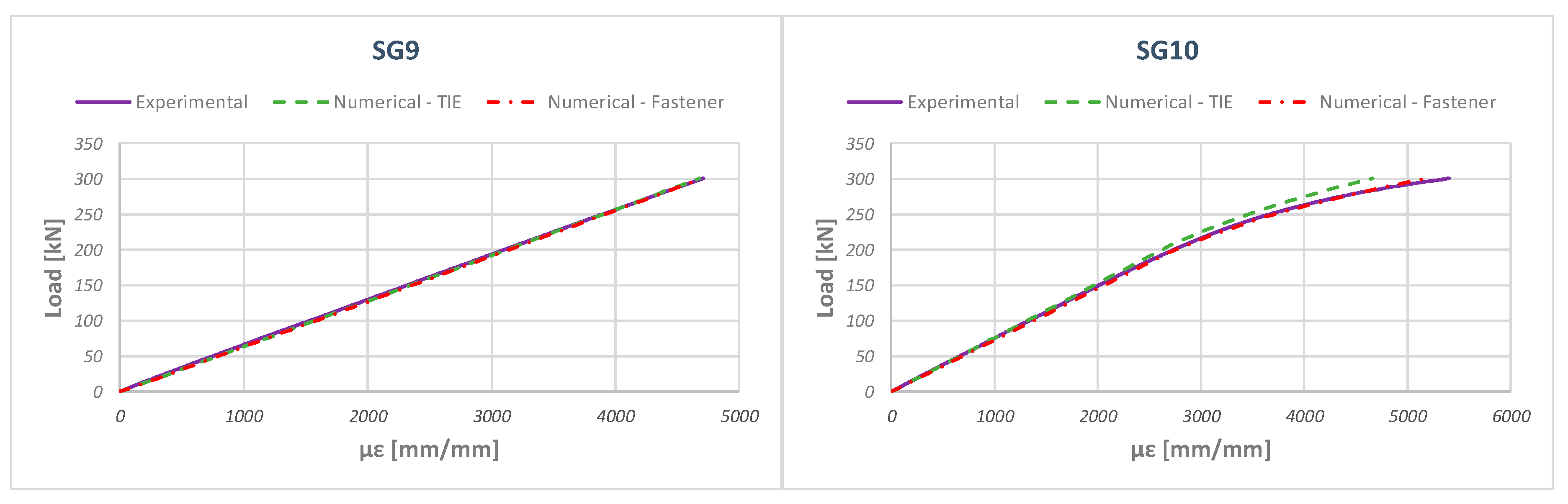
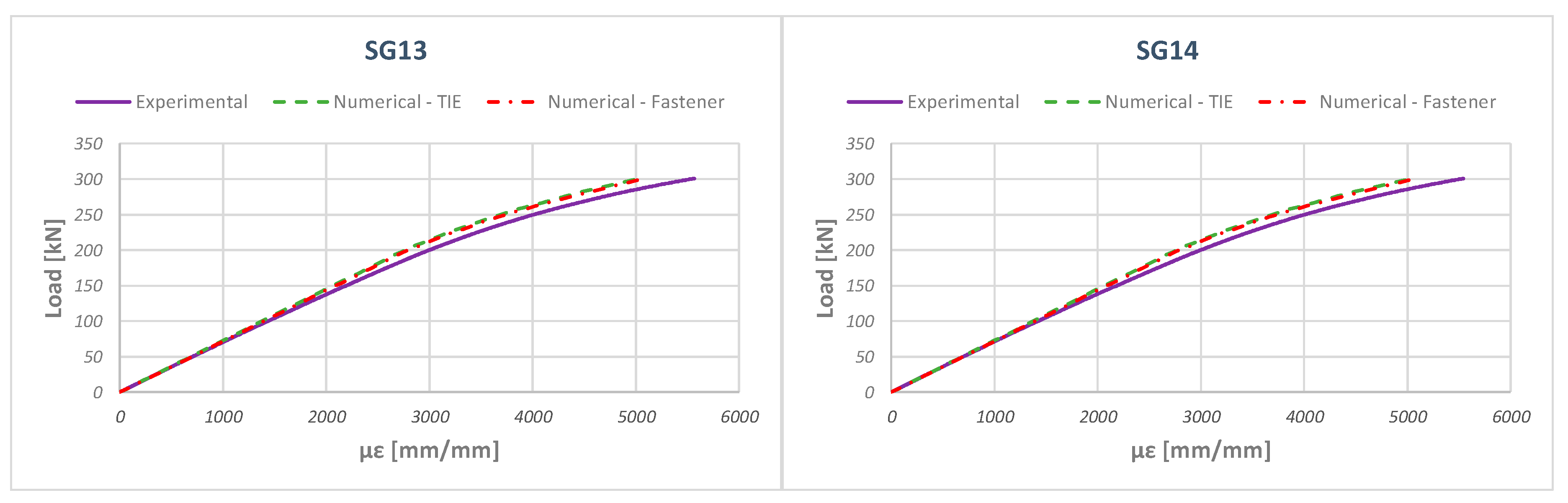
5. Numerical–Experimental Correlation

In this section, the numerical results, obtained by means of the previously described numerical model, are compared to the data recorded during the experimental test. In particular, the strains, obtained from the experimental test, are compared to the strains predicted at strain gauges locations for both the Tie and the Fastener numerical models.
Figure 12, Figure 13, Figure 14, Figure 15, Figure 16, Figure 17 and Figure 18 report the numerical-experimental comparisons at strain gauge locations on the stringers (SG-1, SG-2, SG-5, and SG-6), on the composite skin (SG-3, SG-4, SG-7, SG-8, and SG-9), and on the aluminium skin (SG-10, SG-11, SG-12, SG-13, and SG-14). It is worth noting that, for this kind of test, a maximum deviation equal to ±5% can be observed in the experimental data [60,61].
According to Figure 13, Figure 14, Figure 15, Figure 16, Figure 17 and Figure 18, good agreement is found between the experimentally measured strains and those predicted by the numerical TIE model; while an excellent agreement is found between the experiment and the numerical Fasteners model which uses fastener connectors to couple the structure components. Indeed, the fastener model is able to provide a more realistic deformation field of the structure resulting in a less stiff global behaviour when compared to the TIE model. This behaviour is confirmed by Figure 19, which introduces the comparison between the stiffness of the investigated numerical models. Finally, Figure 20 shows details of the displacements of the Tie and Fastener numerical models. From this figure, the capability of the Fastener-based numerical model to allow the relative displacement of all the structure subcomponents can be appreciated.
As already remarked, Hashin’s failure criteria were used to investigate the damage behaviour of the composite sub-components. Indeed, no damage occurred in composite sub-components if a tensile load of 300 kN was applied. This is confirmed by Figure 21 and Figure 22, which introduce the values of the Hashin’s failure criteria, respectively, for the fibres and for the matrix phases resulting from the Fasteners-based numerical model. Moreover, in Figure 21 and Figure 22 the values of the Hashin’s failure criteria induced by the stress concentration due to the fastener can be appreciated. Indeed, the different material characteristics of the CFRP and metal regions result in a complex stress field at their interface. The faster formulation adopted in this work allows the transfer of concentrated loads between the metal and CFRP regions. Despite the fact that this approach could lead to different predicted results at the interface, the results from a macroscopic point of view can be considered acceptable in terms of stress transfer between the CFRP and metal regions.
Finally, the predicted plastic deformations in the metallic region, when a tensile load of 300 kN is applied, are introduced in Figure 23. Indeed, the metallic plate experiences plastic deformations; however, as expected, an increase of the metallic skin thickness would restrain plasticity, as confirmed by the fact that the metal portion of the metal skin coupled with the doubler (see Figure 10) does not experience any plastic deformation.

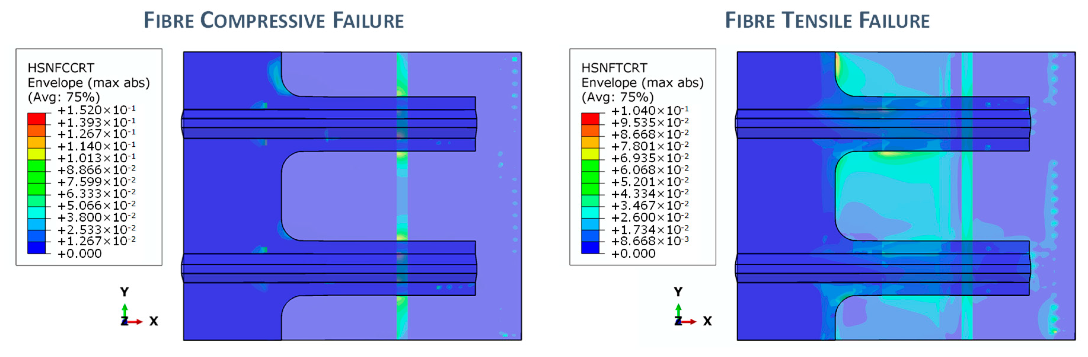
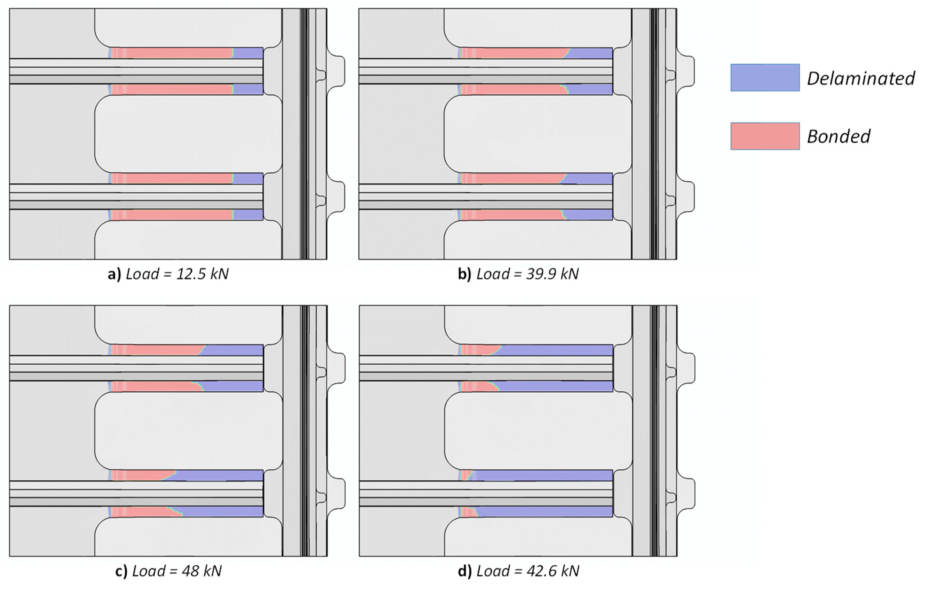
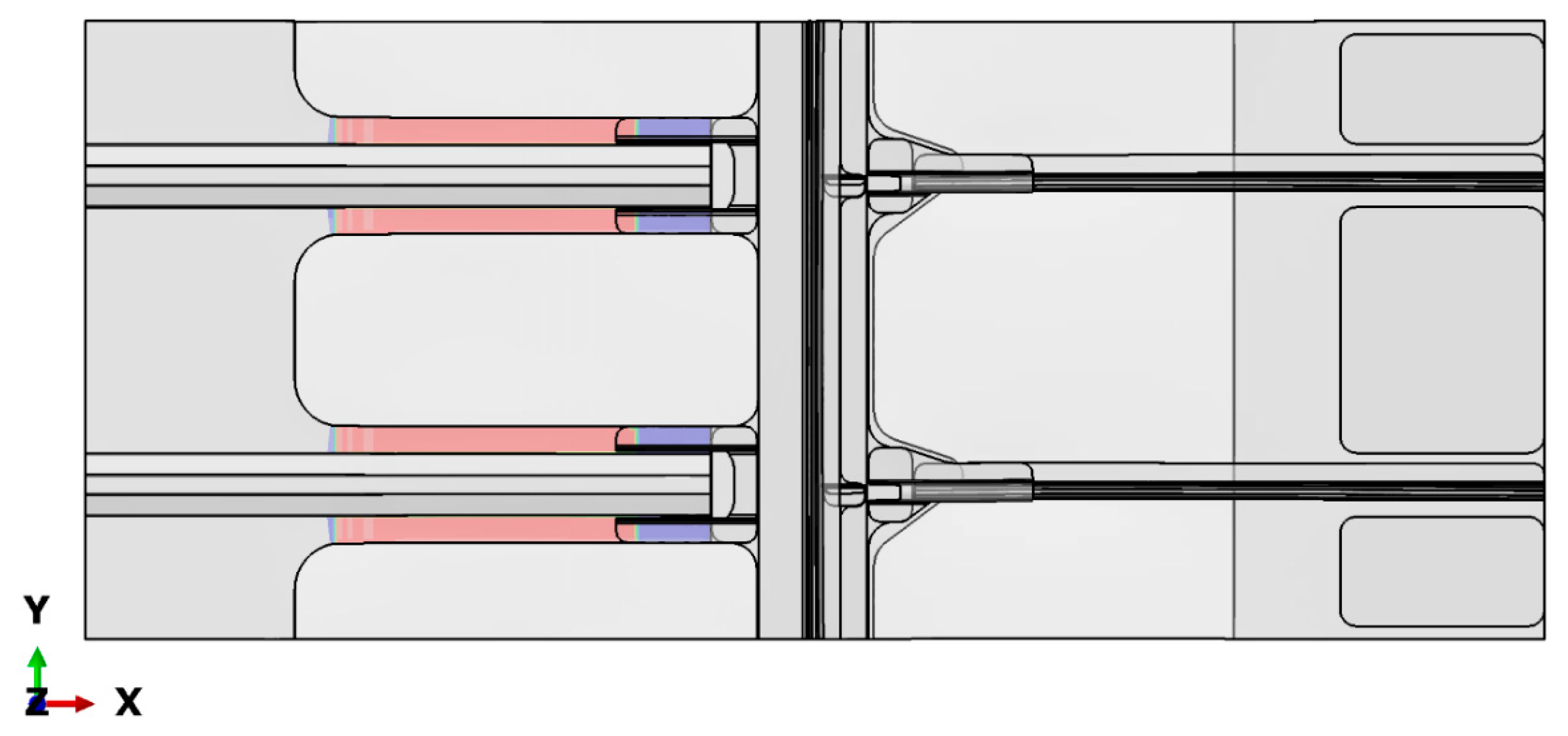
6. Sensitivity Analysis on the Inter-Laminar Damage Behaviour

In this section, the sensitivity analysis performed to assess the influence of the omega stringer joints on the damage behaviour of the composite components of the structure is summarized. An initial artificial 70 mm-long debonding was introduced between the interface of the composite skin and stringers. Then, the virtual crack closure technique (VCCT) [57] was adopted to numerically simulate the skin-stringer debonding growth in configurations with and without the omega stringer joints (see Figure 24). By comparing the results obtained on these configurations, in terms of skin-stringer debonding growth, for a tensile applied displacement equal to 2.5 mm (which is, actually, the displacement at collapse for the configuration without omega stringer joints) the effects of the omega stringer joints on debonding evolution were assessed.
Figure 25 reports the tensile load as a function of the applied displacement for both the investigated configurations (with and without omega stringer joints).
According to Figure 25, the maximum tensile load reached by the configuration without omega joints is 48 kN, which is considerably lower if compared to the 160 kN tensile load reached by the configuration with the omega joints. Indeed, in the model without omega stringer joints, the propagation of the skin-stringer debonding critically reduces the structure-carrying load capability, leading to a premature collapse. This trend is confirmed by Figure 26, which introduces the skin-stringer debonding propagation, in the configuration without omega joints, as the applied displacement increases.
The skin-stringer debonding growth onset occurs at a 12.5 kN load (Figure 26a). The skin-stringer debonding then propagates at both skin-stringer interfaces, up to the maximum applied tensile load of 48 kN (see Figure 26c) at which structural collapse takes place (see Figure 26d).
In contrast, the skin-stringer debonded area in the configuration with the omega joint (shown in Figure 27) does not increase, reaching a maxim applied tensile load of 160 kN for an applied displacement of 2.5 mm as confirmed by Figure 25.

7. Conclusions

In this work, a numerical–experimental investigation into the mechanical behaviour of a fastened hybrid composite–metal stiffened panel has been presented. For numerical predictions, the fasteners have been simulated by using a tie approach and ABAQUS connectors. Both the numerical models take into account the damage behaviour of composite sub-components by Hashin failure criteria while plasticity has been considered for the metallic sub-components.
The numerical results have been correlated to data recorded from an experimental tensile test for a first preliminary validation of the adopted numerical approach. From this comparison, the fastener-based numerical model was revealed to be more accurate, if compared to the tie-based model, in predicting the experimental response in terms of deformations. Actually, tie constraints introduce excessive bonding between the sub-components without allowing the expected relative displacements between them. This preliminary numerical–experimental study demonstrated that the investigated hybrid panel does not experience any damage in composite sub-components up to a tensile load of 300 kN; while, at this loading level, some metallic sub-components experience extensive plastic deformation.
An additional sensitivity numerical analysis has been performed to assess the influence of omega stringer joints on the inter-laminar damage evolution in composite sub-components. Indeed, the virtual crack closure technique has been used to investigate the effect of the omega stringer joints on the evolution of an artificial debonding inserted between composite skin and stringers under tensile loading conditions. Numerical analysis demonstrated that the omega stringer joints are able to arrest the skin-stringer debonding growth avoiding a drastic reduction of the load-carrying capability of the panel.

Author Contributions

All authors equally contribute to this work. All authors have read and agreed to the published version of the manuscript.

Funding

This research received no external funding.

Conflicts of Interest

The authors declare no conflict of interest.

References

  1. Sellitto, A.; Riccio, A.; Russo, A.; Zarrelli, M.; Toscano, C.; Lopresto, V. Compressive behaviour of a damaged omega stiffened panel: Damage detection and numerical analysis. Compos. Struct. 2019, 209, 300–316. [Google Scholar] [CrossRef]
  2. Li, X.; Gao, W.; Liu, W. Post-buckling progressive damage of CFRP laminates with a large-sized elliptical cutout subjected to shear loading. Compos. Struct. 2015, 128, 313–321. [Google Scholar] [CrossRef]
  3. Benedetti, I.; Gulizzi, V. A grain-scale model for high-cycle fatigue degradation in polycrystalline materials. Int. J. Fatigue 2018, 116, 90–105. [Google Scholar] [CrossRef]
  4. Benedetti, I.; Nguyen, H.; Soler-Crespo, R.A.; Gao, W.; Mao, L.; Ghasemi, A.; Wen, J.; Nguyen, S.; Espinosa, H.D. Formulation and validation of a reduced order model of 2D materials exhibiting a two-phase microstructure as applied to graphene oxide. J. Mech. Phys. Solids 2018, 112, 66–88. [Google Scholar] [CrossRef]
  5. Milazzo, A.; Benedetti, I.; Gulizzi, V. An extended Ritz formulation for buckling and post-buckling analysis of cracked multilayered plates. Compos. Struct. 2018, 201, 980–994. [Google Scholar] [CrossRef]
  6. Riccio, A.; Linde, P.; Raimondo, A.; Buompane, A.; Sellitto, A. On the use of selective stitching in stiffened composite panels to prevent skin-stringer debonding. Compos. Part B Eng. 2017, 124, 64–75. [Google Scholar] [CrossRef]
  7. Zhu, G.; Sun, G.; Liu, Q.; Li, G.; Li, Q. On crushing characteristics of different configurations of metal-composites hybrid tubes. Compos. Struct. 2017, 175, 58–69. [Google Scholar] [CrossRef]
  8. Zhu, G.; Sun, G.; Yu, H.; Li, S.; Li, Q. Energy absorption of metal, composite and metal/composite hybrid structures under oblique crushing loading. Int. J. Mech. Sci. 2018, 135, 458–483. [Google Scholar] [CrossRef]
  9. Kumar, P.; Rai, B. Delaminations of barely visible impact damage in CFRP laminates. Compos. Struct. 1993, 23, 313–318. [Google Scholar] [CrossRef]
  10. Rogge, M.D.; Leckey, C.A.C. Characterization of impact damage in composite laminates using guided wavefield imaging and local wavenumber domain analysis. Ultrasonics 2013, 53, 1217–1226. [Google Scholar] [CrossRef]
  11. Angelidis, N.; Irving, P.E. Detection of impact damage in CFRP laminates by means of electrical potential techniques. Compos. Sci. Technol. 2007, 67, 594–604. [Google Scholar] [CrossRef]
  12. Romano, F.; Di Caprio, F.; Mercurio, U. Compression after impact analysis of composite panels and equivalent hole method. Procedia Eng. 2016, 167, 182–189. [Google Scholar] [CrossRef]
  13. Borrelli, R.; Franchitti, S.; Di Caprio, F.; Mercurio, U.; Zallo, A. A repair criterion for impacted composite structures based on the prediction of the residual compressive strength. Procedia Eng. 2014, 88, 117–124. [Google Scholar] [CrossRef]
  14. Borrelli, R.; Franchitti, S.; Di Caprio, F.; Romano, F.; Mercurio, U. A numerical procedure for the virtual compression after impact analysis. Adv. Compos. Lett. 2015, 24, 57–67. [Google Scholar] [CrossRef]
  15. Perner, M.; Algermissen, S.; Keimer, R.; Monner, H.P. Avoiding defects in manufacturing processes: A review for automated CFRP production. Robot. Comput.-Integr. Manuf. 2016, 38, 82–92. [Google Scholar] [CrossRef]
  16. Ma, L.; Soleimani, M. Hidden defect identification in carbon fibre reinforced polymer plates using magnetic induction tomography. Meas. Sci. Technol. 2014, 25, 055404. [Google Scholar] [CrossRef]
  17. Hörrmann, S.; Adumitroaie, A.; Schagerl, M. The effect of ply folds as manufacturing defect on the fatigue life of CFRP materials. Frattura ed Integrita Strutturale 2016, 10, 76–81. [Google Scholar] [CrossRef] [Green Version]
  18. Wang, P.; Lei, H.; Zhu, X.; Chen, H.; Wang, C.; Fang, D. Effect of manufacturing defect on mechanical performance of plain weave carbon/epoxy composite based on 3D geometrical reconstruction. Compos. Struct. 2018, 199, 38–52. [Google Scholar] [CrossRef]
  19. Pramanik, A. Developments in the non-traditional machining of particle reinforced metal matrix composites. Int. J. Mach. Tools Manuf. 2014, 86, 44–61. [Google Scholar] [CrossRef] [Green Version]
  20. Pramanik, A.; Basak, A.K.; Dong, Y.; Sarker, P.K.; Uddin, M.S.; Littlefair, G.; Dixit, A.R.; Chattopadhyaya, S. Joining of carbon fibre reinforced polymer (CFRP) composites and aluminium alloys—A review. Compos. Part A Appl. Sci. Manuf. 2017, 101, 1–29. [Google Scholar] [CrossRef] [Green Version]
  21. Riccio, A.; Ricchiuto, R.; Di Caprio, F.; Sellitto, A.; Raimondo, A. Numerical investigation of constitutive material models on bonded joints in scarf repaired composite laminates. Eng. Fract. Mech. 2017, 173, 91–106. [Google Scholar] [CrossRef]
  22. Rhee, K.Y.; Choi, N.-S.; Park, S.-J. Effect of plasma treatment of aluminum on the bonding characteristics of aluminum-CFRP composite joints. J. Adhes. Sci. Technol. 2002, 16, 1487–1500. [Google Scholar] [CrossRef]
  23. Jumbo, F.; Ruiz, P.D.; Yu, Y.; Swallowe, G.M.; Ashcroft, I.A.; Huntley, J.M. Experimental and numerical investigation of mechanical and thermal residual strains in adhesively bonded joints. Strain 2007, 43, 319–331. [Google Scholar] [CrossRef]
  24. Zhang, K.; Yang, Z.; Li, Y. A method for predicting the curing residual stress for CFRP/Al adhesive single-lap joints. Int. J. Adhes. Adhes. 2013, 46, 7–13. [Google Scholar] [CrossRef]
  25. Ishii, K.; Imanaka, M.; Nakayama, H.; Kodama, H. Evaluation of the fatigue strength of adhesively bonded CFRP/metal single and single-step double-lap joints. Compos. Sci. Technol. 1999, 59, 1675–1683. [Google Scholar] [CrossRef]
  26. Biscaia, H.; Cardoso, J.; Chastre, C. A finite element based analysis of double strap bonded joints with CFRP and aluminium. Key Eng. Mater. 2017, 754, 237–240. [Google Scholar] [CrossRef]
  27. Ruiz, P.D.; Jumbo, F.; Huntley, J.M.; Ashcroft, I.A.; Swallowe, G.M. Experimental and numerical investigation of strain distributions within the adhesive layer in bonded joints. Strain 2011, 47, 88–104. [Google Scholar] [CrossRef]
  28. Tinkloh, S.; Wu, T.; Tröster, T.; Niendorf, T. A micromechanical-based finite element simulation of process-induced residual stresses in metal-CFRP-hybrid structures. Compos. Struct. 2020, 238, 111926. [Google Scholar] [CrossRef]
  29. Tsokanas, P.; Loutas, T.; Kotsinis, G.; Kostopoulos, V.; van den Brink, W.M.; Martin de la Escalera, F. On the fracture toughness of metal-composite adhesive joints with bending-extension coupling and residual thermal stresses effect. Compos. Part B Eng. 2020, 185, 107694. [Google Scholar] [CrossRef]
  30. Xiao, Y.; Ishikawa, T. Bearing strength and failure behavior of bolted composite joints (part I: Experimental investigation). Compos. Sci. Technol. 2005, 65, 1022–1031. [Google Scholar] [CrossRef]
  31. Xiao, Y.; Ishikawa, T. Bearing strength and failure behavior of bolted composite joints (part II: Modeling and simulation). Compos. Sci. Technol. 2005, 65, 1032–1043. [Google Scholar] [CrossRef]
  32. Irisarri, F.-X.; Laurin, F.; Carrere, N.; Maire, J.-F. Progressive damage and failure of mechanically fastened joints in CFRP laminates-Part I: Refined Finite Element modelling of single-fastener joints. Compos. Struct. 2012, 94, 2269–2277. [Google Scholar] [CrossRef]
  33. Irisarri, F.-X.; Laurin, F.; Carrere, N.; Maire, J.-F. Progressive damage and failure of mechanically fastened joints in CFRP laminates-Part II: Failure prediction of an industrial junction. Compos. Struct. 2012, 94, 2278–2284. [Google Scholar] [CrossRef]
  34. Madukauwa-David, I.D.; Drissi-Habti, M. Numerical simulation of the mechanical behavior of a large smart composite platform under static loads. Compos. Part B Eng. 2016, 88, 19–25. [Google Scholar] [CrossRef]
  35. Antony, S.; Drissi-Habti, M.; Raman, V. Numerical Analysis to Enhance Delamination Strength around Bolt Holes of Unidirectional Pultruded Large Smart Composite Platform. Adv. Mater. Sci. Eng. 2018, 2018, 3154904. [Google Scholar] [CrossRef] [Green Version]
  36. Benezech, L.; Landon, Y.; Rubio, W. Study of manufacturing defects and tool geometry optimisation for multi-material stack drilling. Adv. Mater. Res. 2012, 423, 1–11. [Google Scholar] [CrossRef]
  37. Zitoune, R.; Krishnaraj, V.; Sofiane Almabouacif, B.; Collombet, F.; Sima, M.; Jolin, A. Influence of machining parameters and new nano-coated tool on drilling performance of CFRP/Aluminium sandwich. Compos. Part B Eng. 2012, 43, 1480–1488. [Google Scholar] [CrossRef]
  38. Breziner, L.; Hutapea, P. Influence of harsh environmental conditions on CFRP-aluminum single lap joints. Aircr. Eng. Aerosp. Technol. 2008, 80, 371–377. [Google Scholar] [CrossRef]
  39. Coman, C.-D.; Pelin, G. Thermal effects on single-Lap, single-Bolt, hybrid metal—Composite joint stiffness. Incas Bull. 2018, 10, 75–88. [Google Scholar]
  40. Ueda, M.; Miyake, S.; Hasegawa, H.; Hirano, Y. Instantaneous mechanical fastening of quasi-isotropic CFRP laminates by a self-piercing rivet. Compos. Struct. 2012, 94, 3388–3393. [Google Scholar] [CrossRef]
  41. Hoang, N.-H.; Langseth, M.; Porcaro, R.; Hanssen, A.-G. The effect of the riveting process and aging on the mechanical behaviour of an aluminium self-piercing riveted connection. Eur. J. Mech. A/Solids 2011, 30, 619–630. [Google Scholar] [CrossRef]
  42. Hoang, N.-H.; Porcaro, R.; Langseth, M.; Hanssen, A.-G. Self-piercing riveting connections using aluminium rivets. Int. J. Solids Struct. 2010, 47, 427–439. [Google Scholar] [CrossRef] [Green Version]
  43. Pickin, C.G.; Young, K.; Tuersley, I. Joining of lightweight sandwich sheets to aluminium using self-pierce riveting. Mater. Des. 2007, 28, 2361–2365. [Google Scholar] [CrossRef]
  44. Landgrebe, D.; Jäckel, M.; Niegsch, R. Influence of process induced damages on joint strength when self-pierce riveting carbon fiber reinforced plastics with aluminum. Key Eng. Mater. 2015, 651–653, 1493–1498. [Google Scholar] [CrossRef]
  45. Rao, H.M.; Kang, J.; Huff, G.; Avery, K.; Su, X. Impact of rivet head height on the tensile and fatigue properties of lap shear self-pierced riveted CFRP to aluminum. SAE Int. J. Mater. Manuf. 2017, 10, 167–173. [Google Scholar] [CrossRef]
  46. Kweon, J.-H.; Jung, J.-W.; Kim, T.-H.; Choi, J.-H.; Kim, D.-H. Failure of carbon composite-to-aluminum joints with combined mechanical fastening and adhesive bonding. Compos. Struct. 2006, 75, 192–198. [Google Scholar] [CrossRef]
  47. Matsuzaki, R.; Shibata, M.; Todoroki, A. Improving performance of GFRP/aluminum single lap joints using bolted/co-cured hybrid method. Compos. Part A Appl. Sci. Manuf. 2008, 39, 154–163. [Google Scholar] [CrossRef]
  48. Di Franco, G.; Zuccarello, B. Analysis and optimization of hybrid double lap aluminum-GFRP joints. Compos. Struct. 2014, 116, 682–693. [Google Scholar] [CrossRef] [Green Version]
  49. Fu, M.; Mallick, P.K. Fatigue of hybrid (adhesive/bolted) joints in SRIM composites. Int. J. Adhes. Adhes. 2001, 21, 145–159. [Google Scholar] [CrossRef]
  50. Di Franco, G.; Fratini, L.; Pasta, A. Analysis of the mechanical performance of hybrid (SPR/bonded) single-lap joints between CFRP panels and aluminum blanks. Int. J. Adhes. Adhes. 2013, 41, 24–32. [Google Scholar] [CrossRef]
  51. Barut, A.; Madenci, E. Analysis of bolted-bonded composite single-lap joints under combined in-plane and transverse loading. Compos. Struct. 2009, 88, 579–594. [Google Scholar] [CrossRef]
  52. Kapidžić, Z.; Nilsson, L.; Ansell, H. Finite element modeling of mechanically fastened composite-aluminum joints in aircraft structures. Compos. Struct. 2014, 109, 198–210. [Google Scholar] [CrossRef]
  53. Hochard, C.; Payan, J.; Bordreuil, C. A progressive first ply failure model for woven ply CFRP laminates under static and fatigue loads. Int. J. Fatigue 2006, 28, 1270–1276. [Google Scholar] [CrossRef]
  54. Guild, F.J.; Vrellos, N.; Drinkwater, B.W.; Balhi, N.; Ogin, S.L.; Smith, P.A. Intra-laminar cracking in CFRP laminates: Observations and modelling. J. Mater. Sci. 2006, 41, 6599–6609. [Google Scholar] [CrossRef]
  55. Reiner, J.; Feser, T.; Schueler, D.; Waimer, M.; Vaziri, R. Comparison of two progressive damage models for studying the notched behavior of composite laminates under tension. Compos. Struct. 2019, 207, 385–396. [Google Scholar] [CrossRef]
  56. Gong, W.; Chen, J.; Patterson, E.A. An experimental study of the behaviour of delaminations in composite panels subjected to bending. Compos. Struct. 2015, 123, 9–18. [Google Scholar] [CrossRef]
  57. Riccio, A.; Russo, A.; Sellitto, A.; Raimondo, A. Development and application of a numerical procedure for the simulation of the “Fibre Bridging” phenomenon in composite structures. Compos. Struct. 2017, 168, 104–119. [Google Scholar] [CrossRef]
  58. Lévêque, D.; Schieffer, A.; Mavel, A.; Maire, J.-F. Analysis of how thermal aging affects the long-term mechanical behavior and strength of polymer-matrix composites. Compos. Sci. Technol. 2005, 65, 395–401. [Google Scholar] [CrossRef]
  59. De Luca, A.; Caputo, F. A review on analytical failure criteria for composite materials. Aims Mater. Sci. 2017, 4, 1165–1185. [Google Scholar] [CrossRef]
  60. Khadyko, M.; Dumoulin, S.; Børvik, T.; Hopperstad, O.S. An experimental-numerical method to determine the work-hardening of anisotropic ductile materials at large strains. Int. J. Mech. Sci. 2014, 88, 25–36. [Google Scholar] [CrossRef]
  61. Frodal, B.H.; Dæhli, L.E.B.; Børvik, T.; Hopperstad, O.S. Modelling and simulation of ductile failure in textured aluminium alloys subjected to compression-tension loading. Int. J. Plast. 2019, 118, 36–69. [Google Scholar] [CrossRef]
Figure 1. Geometrical description, materials, and boundary conditions of the investigated structure (dimensions in mm).
Applsci 10 01880 g001
Figure 2. Geometrical model: isometric views.
Applsci 10 01880 g002
Figure 3. Stacking sequences in the skin.
Applsci 10 01880 g003
Figure 4. Stacking sequences in the stringers.
Applsci 10 01880 g004
Figure 5. Strain gauge locations.
Applsci 10 01880 g005
Figure 6. Hybrid panel (back side) including clamps.
Applsci 10 01880 g006
Figure 7. Test rig.
Figure 7. Test rig.
Applsci 10 01880 g007
Figure 8. Finite element model (FEM).
Applsci 10 01880 g008
Figure 9. Bilinear plastic model.
Applsci 10 01880 g009
Figure 10. Bonded regions.
Applsci 10 01880 g010
Figure 11. Fastener locations.
Applsci 10 01880 g011
Figure 12. Numerical–experimental comparisons for SG-1 and SG-2: numerical TIE and Fasteners models.
Applsci 10 01880 g012
Figure 13. Numerical–experimental comparisons for SG-3 and SG-4: numerical TIE and Fasteners models.
Applsci 10 01880 g013
Figure 14. Numerical–experimental comparisons for SG-5 and SG-6: numerical TIE and Fasteners models.
Applsci 10 01880 g014
Figure 15. Numerical–experimental comparisons for SG-7 and SG-8: numerical TIE and Fasteners models.
Applsci 10 01880 g015
Figure 16. Numerical–experimental comparisons for SG-9 and SG-10: numerical TIE and Fasteners models.
Applsci 10 01880 g016
Figure 17. Numerical–experimental comparisons for SG-11 and SG-12: numerical TIE and Fasteners models.
Applsci 10 01880 g017
Figure 18. Numerical–experimental comparisons for SG-13 and SG-14: numerical TIE and Fasteners models.
Applsci 10 01880 g018
Figure 19. TIE and Fastener numerical models’ stiffness comparisons.
Applsci 10 01880 g019
Figure 20. Out of plane displacements at 300 kN (10× deformation factor in the z-direction–units in mm).
Applsci 10 01880 g020
Figure 21. Hashin’s failure criteria: fibre.
Applsci 10 01880 g021
Figure 22. Hashin’s failure criteria: matrix.
Applsci 10 01880 g022
Figure 23. Plastic strains—load: 300 kN.
Applsci 10 01880 g023
Figure 24. Omega stringer joint (in red).
Applsci 10 01880 g024
Figure 25. Load vs. applied displacement.
Applsci 10 01880 g025
Figure 26. Skin-stringer debonding propagation. (a) skin-stringer debonding growth onset; (b) intermediate skin-stringer debonding evolution; (c) maximum attained load; (d) ultimate skin-stringer debonding.
Applsci 10 01880 g026
Figure 27. Omega joint configuration—delaminated area: load = 161 kN.
Applsci 10 01880 g027
Table 1. AA 2024 and AA 7075 mechanical properties.
AA 2024–T42AA 7075–T62
E [MPa]ν [-]E [MPa]ν [-]
72,4000.3371,7000.33
Table 2. IMS/977-2 mechanical properties [58].
IMS/977-2
E1
[MPa]
E2 = E3
[MPa]
G12 = G13
[MPa]
G23
[MPa]
ν12
[-]
GIC
[kJ/m2]
GIIC = GIIIC
[kJ/m2]
152,3108730394028400.340.180.5
XT
[MPa]
XC
[MPa]
YT
[MPa]
YC
[MPa]
ST
[MPa]
SL
[MPa]
GT1C
[kJ/m2]
GT2C
[kJ/m2]
GC1C
[kJ/m2]
GC2C
[kJ/m2]
270013005519040102450.2980.3343.349

