Article

Potential Use of Time-Lapse Surface Seismics for Monitoring Thawing of the Terrestrial Arctic

1
Department of Earth Science, University of Bergen, P.O. Box 7803, 5020 Bergen, Norway
2
ARCEx, UiT The Arctic University of Norway, P.O. Box 6050 Langnes, 9037 Tromsø, Norway
3
Department of Arctic Geology, The University Centre in Svalbard (UNIS), P.O. Box 156, 9171 Longyearbyen, Norway
*
Author to whom correspondence should be addressed.
Appl. Sci. 2020, 10(5), 1875; https://doi.org/10.3390/app10051875
Submission received: 9 February 2020 / Revised: 28 February 2020 / Accepted: 5 March 2020 / Published: 9 March 2020
(This article belongs to the Special Issue Surface Waves for Monitoring of Materials at Different Scales)

Abstract

:

Featured Application

We investigate the feasibility of using seismic data acquired in repeated active experiments for monitoring changes in the degree of freezing in unconsolidated sediments.

Abstract

The terrestrial Arctic is warming rapidly, causing changes in the degree of freezing of the upper sediments, which the mechanical properties of unconsolidated sediments strongly depend upon. This study investigates the potential of using time-lapse surface seismics to monitor thawing of currently (partly) frozen ground utilizing synthetic and real seismic data. First, we construct a simple geological model having an initial temperature of −5 °C, and infer constant surface temperatures of −5 °C, +1 °C, +5 °C, and +10 °C for four years to this model. The geological models inferred by the various thermal regimes are converted to seismic models using rock physics modeling and subsequently seismic modeling based on wavenumber integration. Real seismic data reflecting altered surface temperatures were acquired by repeated experiments in the Norwegian Arctic during early autumn to mid-winter. Comparison of the surface wave characteristics of both synthetic and real seismic data reveals time-lapse effects that are related to thawing caused by varying surface temperatures. In particular, the surface wave dispersion is sensitive to the degree of freezing in unconsolidated sediments. This demonstrates the potential of using surface seismics for Arctic climate monitoring, but inversion of dispersion curves and knowledge of the local near-surface geology is important for such studies to be conclusive.

1. Introduction

Adventdalen is located on Svalbard in the Norwegian Arctic, in an area that traditionally has experienced stable subzero winter temperatures and minimal annual rainfall. However, measurements in recent years show that climate is changing rapidly in this region and in the Arctic in general [1]. The IPCC [2] projects that temperatures and precipitation will continue to increase drastically in the years to come, likely contributing to thawing of currently frozen surfaces, including sea ice, glaciers, snow, and fully or partly frozen ground, often referred to as permafrost. Permafrost is defined as ground that stays at or below 0 °C for at least two years [3], and this purely thermal definition implies that the degree of freezing in permafrost can vary considerably.
Methods for monitoring thawing of permafrost are desirable because thawing of currently frozen ground may have large geomorphic consequences [4]. Frozen ground is stiffer and more rigid than unfrozen ground [5], therefore, subsidence and increased avalanche risk are likely consequences of thawing. Additionally, the large currently frozen land areas in the Northern hemisphere hold huge reserves of carbon that may be released to the atmosphere in the thawing process, inducing further climate change [6]. These methods should preferably be non-intrusive due to efficiency and environmental constraints.
Kneisel, et al. [7] provide an overview of some previously tested geophysical methods for monitoring thawing of permafrost, based on changes in electric, electromagnetic, elastic, or dielectric properties. All methods show limitations, particularly in areas with saline pore water, see [8] for a good overview. Salt causes freezing point depression and gradual freezing of pore water at subzero temperatures because the salinity of the residual pore water increases as salt is expelled when the water freezes [9]. Typical for saline permafrost is therefore unfrozen water within the permafrost, the amount depending on the salinity. If the salinity varies with depth, the amount of ice also varies with depth leading to an irregularly varying stiffness gradient with depth. For such partially frozen soils, the correlation between temperature and resistivity can be complicated [8,10], making electric methods difficult to use. Additionally, refraction seismics cannot be used in such environments, because it will not detect softer layers if these are located below stiffer layers.
Effective elastic properties of a medium depend on the physical properties and quantity of its constituents, as well as their geometrical distribution, which for permafrost typically means sediment grains, water, ice, and air. Thus, since thawing of a frozen material leads to a change in the ice-to-water ratio, referred to as the ice saturation, thawing will change the effective elastic and seismic properties. Laboratory measurements of the seismic properties of permafrost during the freeze-thaw process [8,11] support the idea that elastic properties of unconsolidated sediments decrease with increased thawing, however the relation between the degree of thawing and change in elastic properties is not linear.
Shear modulus of unconsolidated sediments is particularly affected by variation in ice saturation [12], and since surface wave properties strongly depend on the shear modulus, surface wave methods may be a viable option for detecting thawing in permafrost. Multichannel analysis of surface waves (MASW) was first introduced by Park, et al. [13], and has been extensively used for determining the properties of near-surface sediments through inversion of surface wave properties. However, MASW inversion shows limited success for soils with irregular stiffness gradients, and so more sophisticated methods are needed here. Several studies have focused on modified versions of MASW or other surface-wave methods to detect low velocity layers within permafrost with promising results [14,15], since the surface wave properties depend on how the elastic properties of the near-surface sediments vary with depth. For example, Tsuji, et al. [16] detected unfrozen sediments at the base of a glacier on Svalbard using common-midpoint cross-correlation followed by MASW. However, few have used surface wave methods to detect variations in permafrost with time, so-called time-lapse surface seismics. Ajo-Franklin, et al. [17] conducted a controlled warming experiment using distributed acoustic sensing to study the seismic response of such thawing, but we are not aware of any published studies focusing on variations in the seismic signatures of surface waves caused only by natural temperature variations.
The objective of this study is to evaluate the potential of using seismic data in general, and dispersion properties of surface waves in particular, to monitor temporal changes in the permafrost of the Arctic region caused by surface temperature variation. To study this, we make use of both synthetic seismic data generated by seismic modeling, and real time-lapse seismic data obtained by experiments in Adventdalen.

2. Materials and Methods

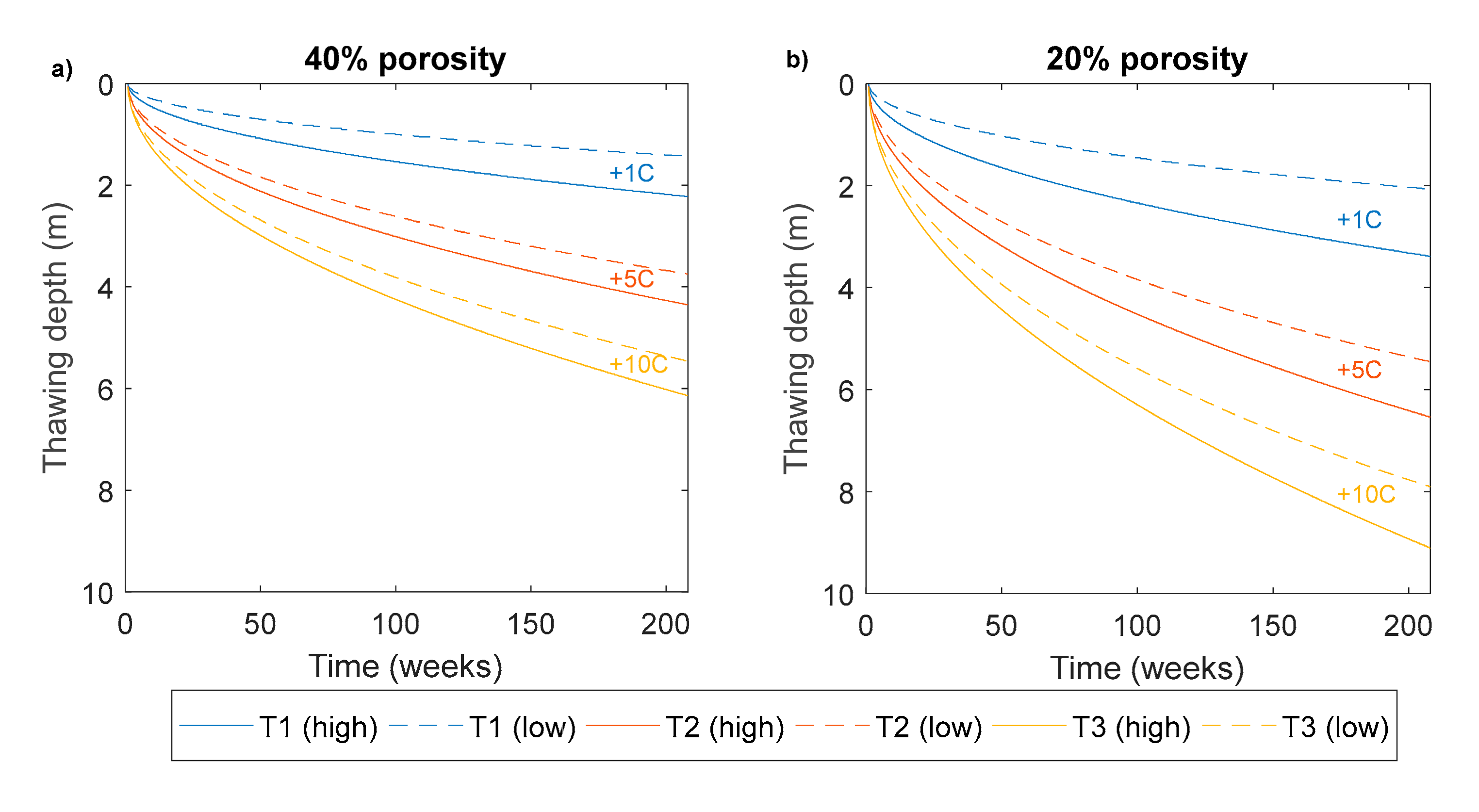
2.1. Modeling Thawing of Frozen Sediments

Heat transport in the subsurface occurs through conduction or convection, where conduction is commonly believed to be the dominant process in permafrost environments except for during extensive spring thawing [18,19]. Heat is conducted downward into the ground if surface temperature is higher than ground temperature, and opposite. Surface temperature is primarily controlled by air temperature, therefore heat flux into the ground is typically largest during summer, but other factors such as snow cover and vegetation also affect surface temperature [3]. If the ground is initially frozen, which is common in the Arctic, this heat flux may cause thawing. In the Arctic today, winter temperatures are generally cold enough so that summer thawing is completely reversed during winter, but if Arctic temperatures increase as they are expected to do [2,20], we will likely see increased thawing of currently frozen ground in the near future.
By considering conduction only, we can describe the strength of the vertical heat flux by the heat transport equation:
C T t + · κ T = Q .
Here, C (Jkg−1K−1) is the volumetric specific heat capacity (in the following referred to as heat capacity), T ( ) is temperature at depth z (m), t is time, κ (Wm−1K−1) is thermal conductivity, and Q (Wm−2) is external heat flux. The effective thermal properties of a composite depend on the thermal properties of the individual constituents and their volume fractions. For permafrost that is typically a matrix, water, ice, and air (in the following defined by subscripts m, w, i, and a, respectively). We also need to include latent heat L (kJ/kg) when one or more of the materials involved changes phase (here: water/ice, L = 333.6 kJ/kg), and following [21], we do this by replacing C with an equivalent heat capacity Ceq that includes latent heat:
C e q = θ m ρ m c m + θ a ρ a c a + θ w ρ w c w + Ф T L + θ i ρ i c i + Ф T L .
Density, heat capacity, and volume fraction of each constituent are defined by ρ n , c n , and θ n , respectively, with subscripts as defined above. Total porosity is θ =   θ a + θ w + θ i , and the volume fractions of water and ice are given by θ w = ( θ θ a ) Ф and θ i = ( θ θ a ) θ w , where Ф is a variable changing from 0 to 1 for fully frozen to fully unfrozen material over the phase change temperature interval. Note that saturation here denotes total fluid content in the pore space, i.e., θ w + θ i θ , while ice saturation denotes the amount of the fluid that is frozen, i.e., θ i θ w + θ i . Furthermore, we parameterize thermal conductivity using the approximation of De Vries [22]:
κ e q = f m θ m κ m   +   f a θ a κ a   +   f w θ w κ w   +   f i θ i κ i θ m f m   +   θ a f a   +   θ w f w +   θ i f i .
The shape factors f n are given by [19] as:
f n = 1 + 1 3 κ n κ 0 1 1 ,
where κ 0 denotes the thermal conductivity of the background medium (here: κ 0 = κ m ).
By assuming that the only heat source is the surface temperature (Q = 0), we can model how temperature distribution evolves with time and depth by using Equation (1) with thermal properties as given by Equations (2)–(4) in a finite-element scheme as provided by COMSOL [23].
Porosity, saturation, and salinity all affect thawing depth in frozen ground because the effective thermal properties of a composite are sensitive to the volume fractions of each constituent. Heat transport in Arctic terrestrial sediments is particularly sensitive to changes in the amount and chemistry of pore water because it may change phase in the temperature range commonly encountered here. In this paper, we assume full saturation and, therefore, porosity is the only factor determining water content. For a material to change phase from a solid to a liquid (e.g., ice to water), energy is absorbed to change the molecular structure of the material, meaning that heat transport to depth slows down. Non-saline water changes phase instantaneously at 0 °C, while salinity leads to gradual phase change and freezing point depression. Expressions were derived by [9] relating temperature to ice saturation, and using these expressions, we can estimate the ice saturation at a given temperature, assuming known salinity. Combining this knowledge with Equation (1), we can now determine how ice saturation evolves with time and depth.
Figure 1 shows the freezing point isotherm computed using Equation (1) for a simple model consisting of quartz sand with initial temperature T0 = −5 °C throughout the sediment column for three different assumptions of surface temperature: T1 is +1 °C, T2 is +5 °C, and T3 is +10 °C. We use typical values for the physical properties of the constituents from [21,24]. All three scenarios are displayed for a high-porosity (Figure 1a) and a low-porosity sand (Figure 1b) and for high-salinity (solid line) and low-salinity pore water (dashed line). It is evident from Figure 1 that higher surface temperature, increased salinity, and lower porosity all lead to increased thawing depth. This is because higher porosity means that a higher ice content needs to thaw for the thawing depth to progress deeper, and higher salinity means that phase change from ice to water is initiated at a lower temperature.

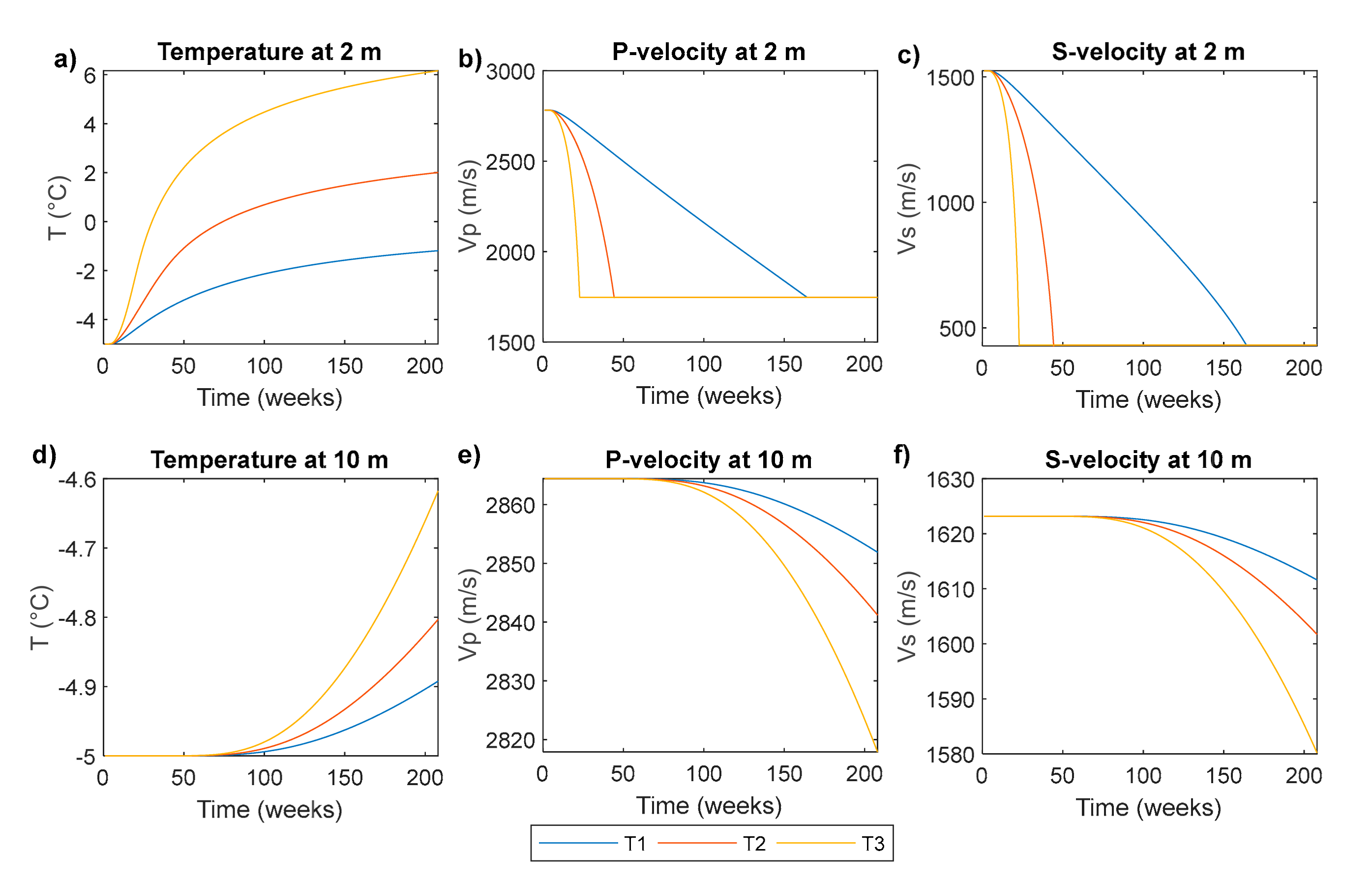
2.2. Modeling Effects of Thawing on Seismic Properties

To understand the effects of thawing and freezing on the elastic properties of unconsolidated, fully saturated near-surface sediments, we refer to papers of Dvorkin et al. [25,26,27] who described the effects of cement (here: ice) forming at various pore-scale configurations on the effective elastic properties of sediments. Ice can form at the grain contacts where it significantly increases the elastic properties, or within the pore space where the effect on effective properties is smaller. Since seismic experiments are dominated by low frequencies (usually <200 Hz), the relevant wavelengths are orders of magnitude larger than the heterogeneities of the sediments. To convert sediment composition and texture to elastic properties, we can adopt standard rock physics principles. In our case, we will consider isotropic sediments, which then elastically are fully characterized by the bulk modulus K and the shear modulus µ. We use a rock physics model similar to the two-end member mixing approach used by Minshull, et al. [28] and Dou, et al. [29] that inherently assumes cementing and pore-filling ice forming simultaneously at all ice saturations. We compute elastic properties of a fully unfrozen composite ( θ i   = 0) by first using Hertz–Mindlin contact theory [30] to compute dry rock properties, and subsequently Gassmann fluid substitution [31] to compute fully water-saturated rock properties. Furthermore, we compute elastic properties of a fully frozen composite ( θ f   = 0) using the self-consistent approach (SCA) as described by [32,33] by assuming penny-shaped ice inclusions and spherical sediment grain inclusions in a background medium with initially unknown properties. Lastly, to find elastic properties of a composite with ice saturation varying from 0% to 100%, we use the Hill average of the modified Hashin–Shtrikman bounds to mix the fully unfrozen and the fully frozen end-members [34]. For completeness, the main procedure for computing elastic properties of thawing or freezing sediments is outlined in Appendix A.
The resulting elastic properties can together with density ρ be input to the equations for seismic P- and S-wave velocities Vp and Vs, respectively:
V p = K + 4 3   µ / ρ ,
and
V s = µ / ρ .
Combining the resulting velocities with Equation (1), we can determine how seismic velocities vary with time and depth. The complete approach of combing heat flux modeling, rock physics modeling, and the equations for seismic velocities to investigate how seismic velocities vary with time is described in detail in [35].
Figure 2 shows the result of using this approach on high-porosity sand with high-salinity pore water, considering scenarios T1, T2, and T3 (solid lines in Figure 1a). The figure shows how velocities at two stationary points in the subsurface: 2 m depth (Figure 2b,c) and 10 m depth (Figure 2e,f), vary with time. The resulting velocity variations are consistent with the temperature variation with time at these two depths (Figure 2a,d): as temperatures increase, velocities decrease because the water content increases. The largest velocity change is at 2 m depth, consistent with the larger temperature change at 2 m depth than at 10 m depth because less heat is conducted down to 10 m depth.
Figure 3 shows how temperature varies with depth at the last time step in Figure 2 for the scenarios T0, T1, and T3, for a 20 m thick model consisting of four layers. Each layer is quartz sand, but the porosity decreases with depth to mimic a compaction effect, as pressure increases with depth due to increased sediment load. A lower porosity means lesser effects of thawing on the elastic properties, because less material changes phase. For T1 and T3, the temperature distribution in the sediment column has significantly altered from the initial state, and the effects of this change are also evident in the corresponding seismic velocity profiles in Figure 3b,c. Since the only factor that varies between the models is the temperature, the large velocity change from T0 to T1 and T3 is solely ascribed to effects caused by the change in the thermal regime.

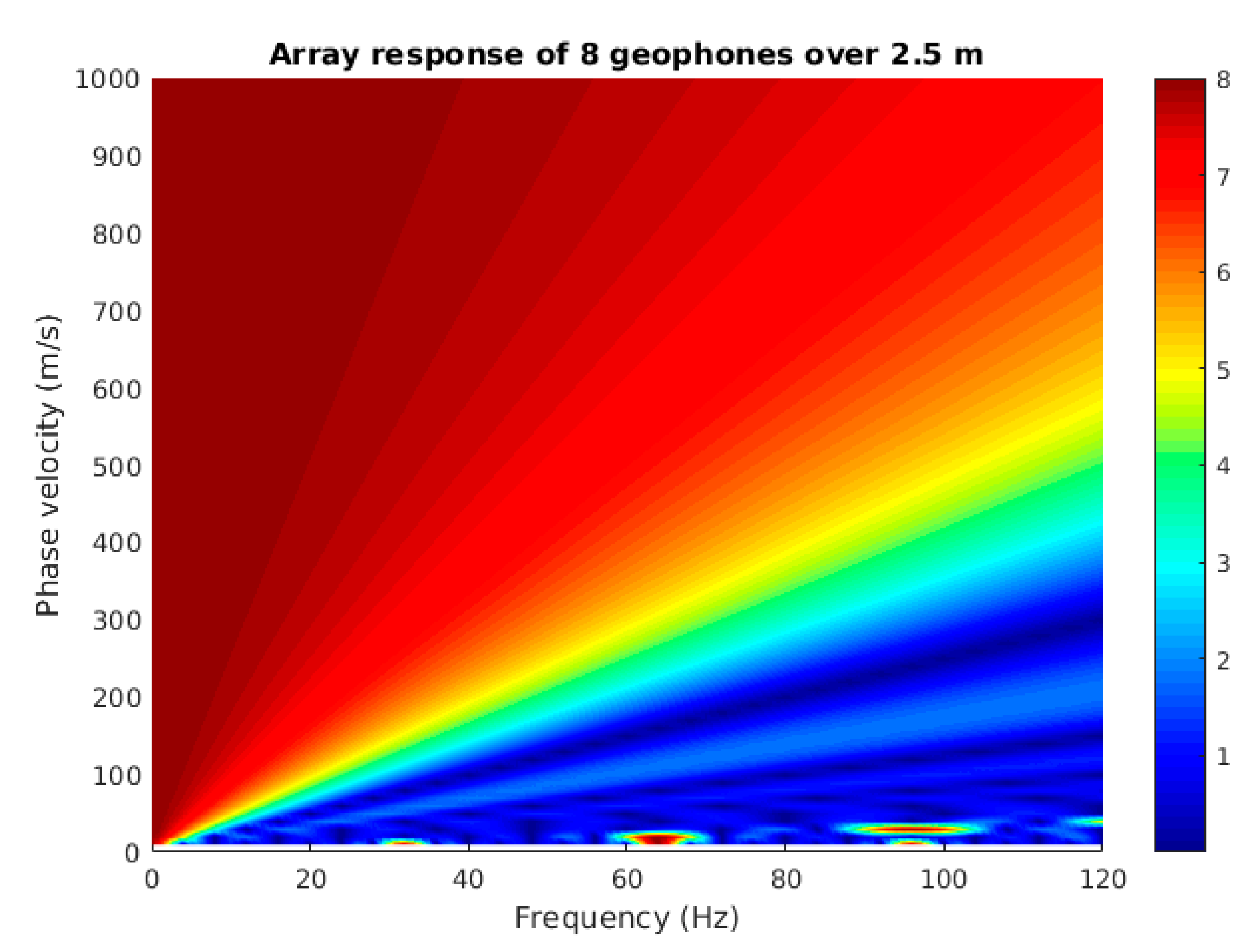
2.3. Surface Seismic Analysis
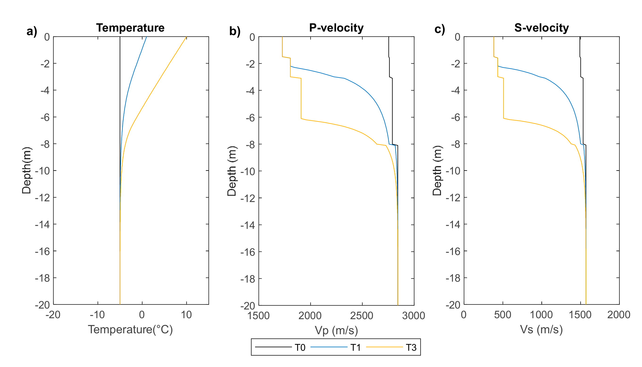
Seismic data acquired in permafrost environments often show strong surface waves [12] and, therefore, we expect to observe these in both synthetic and real seismic data. Vertical geophones record surface waves of Rayleigh type. These propagate in the uppermost sediments of the subsurface as an interaction phenomenon between P- and S-waves. The phase velocity of a Rayleigh wave depends on the elastic properties of the medium that the wave travels in, which for a homogenous medium corresponds to the solution of the following equation [36]:
ζ 3     8 ζ 2   +   8 ζ 3     2 η     16 1     η = 0 ,
where ζ = c R 2 V s 2 and η = V s 2 V p 2 . cR is phase velocity, and Vp and Vs are the P- and S- wave velocities defined by Equations (5) and (6).
There is no frequency dependence inherent in Equation (7), meaning that for a wave propagating in a homogenous medium, all frequency components of the surface wave travel with the same phase velocity cR. However, when a wave propagates along the surface, the amplitude of higher frequencies decreases more rapidly with depth than the lower frequencies; thus, low frequency energy is generally dominating at larger depths. If the elastic properties of the subsurface vary with depth, the various frequency components are influenced by different effective elastic properties, and cR becomes a function of depth and frequency. The equations describing surface wave propagation can then have several solutions (i.e., possible combinations of frequencies and phase velocities), called modes, where the fundamental mode is the solution with the lowest phase velocity for a given frequency [37]. Since the Rayleigh wave is not inherently dispersive, any observed dispersion must be due to varying elastic properties of the near-surface sediments. Equation (7) infers that cR depends on the sediment shear modulus through Vs, which has been shown to strongly respond to freezing/thawing. Thus, an inversion of frequency-dependent surface wave phase velocity for obtaining S-wave velocity with depth can reveal the degree of freezing with depth if the sediment composition is known [38].
To analyze surface wave dispersion, we generate frequency-phase velocity spectra (FV-spectra) by using a wavefield transform. This transform builds an FV-spectrum by decomposing the gather into separate frequency components through Fourier transformation, applying amplitude normalization to each component, and scanning for a range of phase velocities to find the magnitude of summed amplitudes for each frequency component [39]. The FV-spectrum is useful for separating body and surface wave energy, and when the surface wave phase velocity is constant for all frequencies, there is no variation in the elastic properties with depth. Correspondingly, if the FV-spectra of the surface wave vary between equal experiments conducted at different times, this implies a temporal variation of the elastic properties. In our case, this time-lapse effect represents a signal of altered freezing conditions.

3. Results

To investigate the impact of thawing on seismic data, we use seismic gathers and FV-spectra from synthetic seismic data and real seismic data acquired in the Norwegian Arctic.

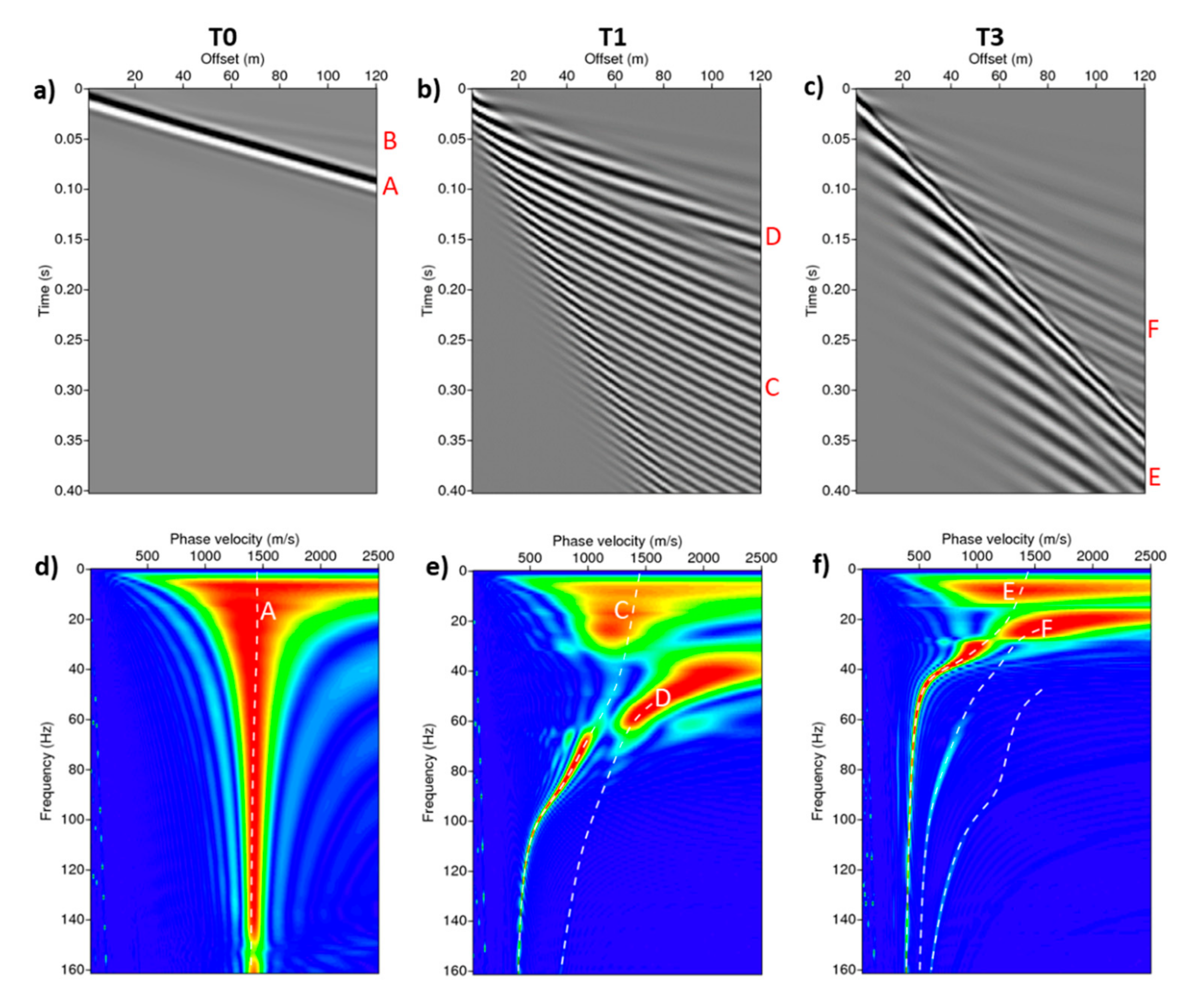
3.1. Synthetic Seismic Data

We use an implementation of the wavenumber integration method called OASES [40] to generate synthetic seismic data corresponding to the velocity models shown in Figure 3. We model the vertical particle displacement for a 120 m-long line with geophones spaced 1 m apart and an impulsive source.
Figure 4a–c show synthetic seismic gathers corresponding to the velocity profiles for T0, T1, and T3 of Figure 3. We observe significant differences between the various gathers, and the complexity of the data increases as the temperature variability with depth increases. For T0, only two events are visible: a non-dispersive strong event travelling at approximately 1450 m/s, which is the fundamental mode of the surface wave (A), and one weaker non-dispersive event travelling at approximately 2700 m/s, which is the direct P-wave (B). The seismic gathers for T1 and T3 are more difficult to interpret, so in addition to the seismic gathers showed here, we make use of computed group velocities and modeling of separate modes of surface waves (as done in normal mode summation [41]). For T1, dispersive waves dominate the wavefield. This includes a wide fan-shaped event with group velocities ranging from approximately 200 m/s to 1450 m/s (C), which is associated with the fundamental mode of the surface wave, and a narrower fan-shaped event with group velocities ranging from approximately 500 m/s to 850 m/s (D), which is the first higher mode. Also for T3, dispersive events dominate the wavefield. The lower fan-shaped event (E) has group velocities ranging from approximately 200 m/s to 1450 m/s, and is the fundamental mode of the surface wave. Amplitudes are particularly high at a group velocity of approximately 380 m/s, which we attribute to the fundamental mode being dispersive at low frequencies, but becoming non-dispersive and correspondingly have a constant group velocity of 380 m/s at higher frequencies. The weaker fan-shaped event (F) is the first higher mode of surface wave with group velocities ranging from 380 m/s to 1000 m/s.
Figure 4d–f show the corresponding FV-spectra, with theoretical modal curves computed from the input models overlaid on the spectra for easier mode identification. Just as with the seismic gathers, there are significant differences between the various models. For T0, the peak in the FV-spectrum appears at fairly constant phase velocities of around 1450 m/s for all frequencies, corresponding with the non-dispersive event observed in Figure 4a. T1 and T3 have similar and constant phase velocities of about 380 m/s at frequencies >120 Hz, but at frequencies between approximately 63 and 120 Hz, phase velocities are higher for T1 than T3. By comparing the FV-spectra with the modal curves, the spectrum peak for T0 corresponds well with the fundamental mode at all frequencies. For T1, it corresponds well with the fundamental mode below 31 Hz and above 63 Hz, and with the first higher mode from 31 to 63 Hz. We observe a weak fundamental mode between 31 and 63 Hz as well, but the first higher mode is dominant. For T3, the modal curves correspond well with the strong fundamental mode in most of the frequency range displayed here, while the first higher mode is dominant in a narrow frequency range of approximately 20 to 30 Hz. We also observe two weak higher modes starting at approximately 60 Hz and 110 Hz, respectively. At low frequencies for all models, we find energy at phase velocities higher than the S-wave velocity in the lower half space, which cannot be normal mode Rayleigh waves and, therefore, we interpret these as leaky wave modes.

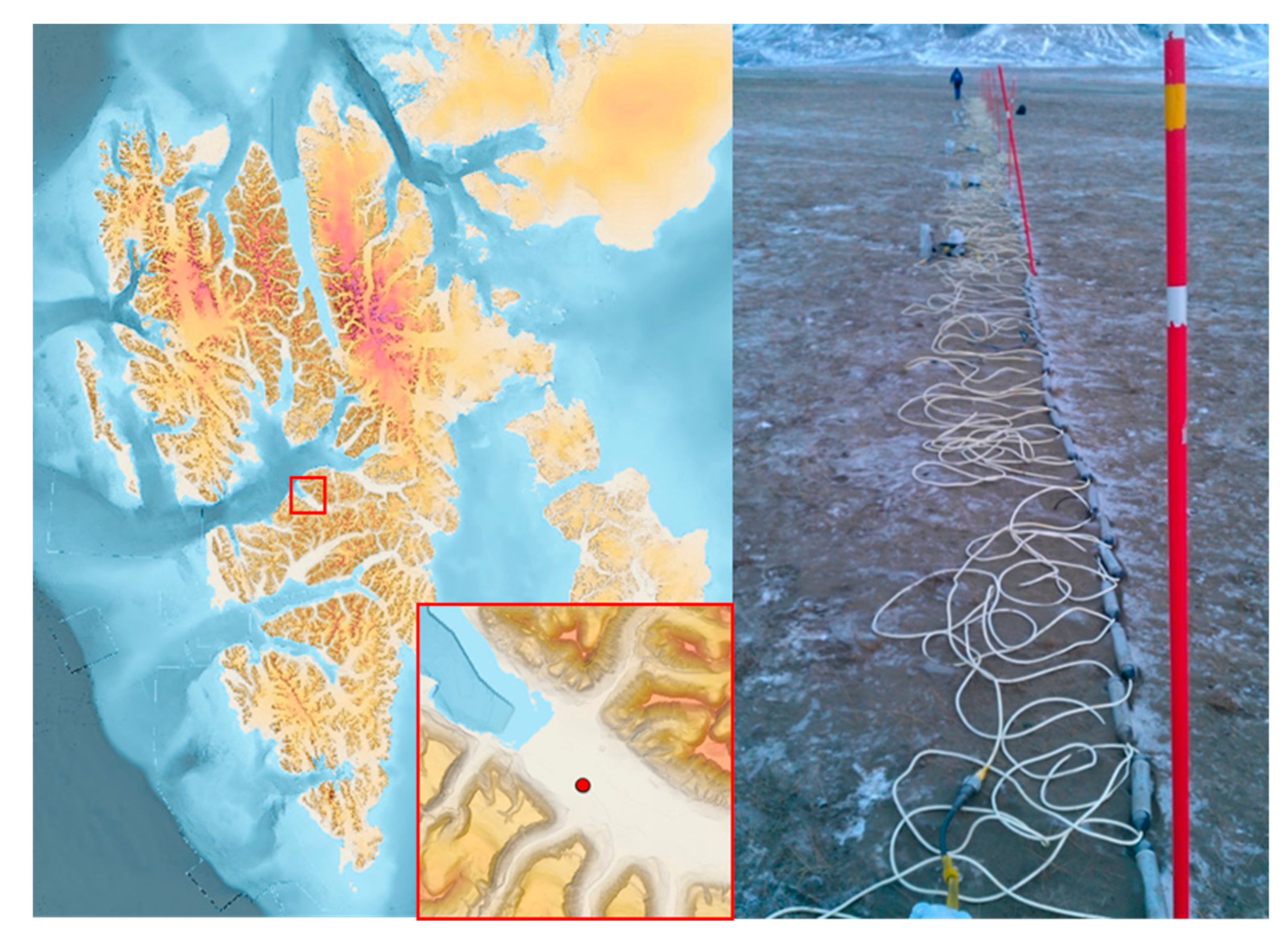
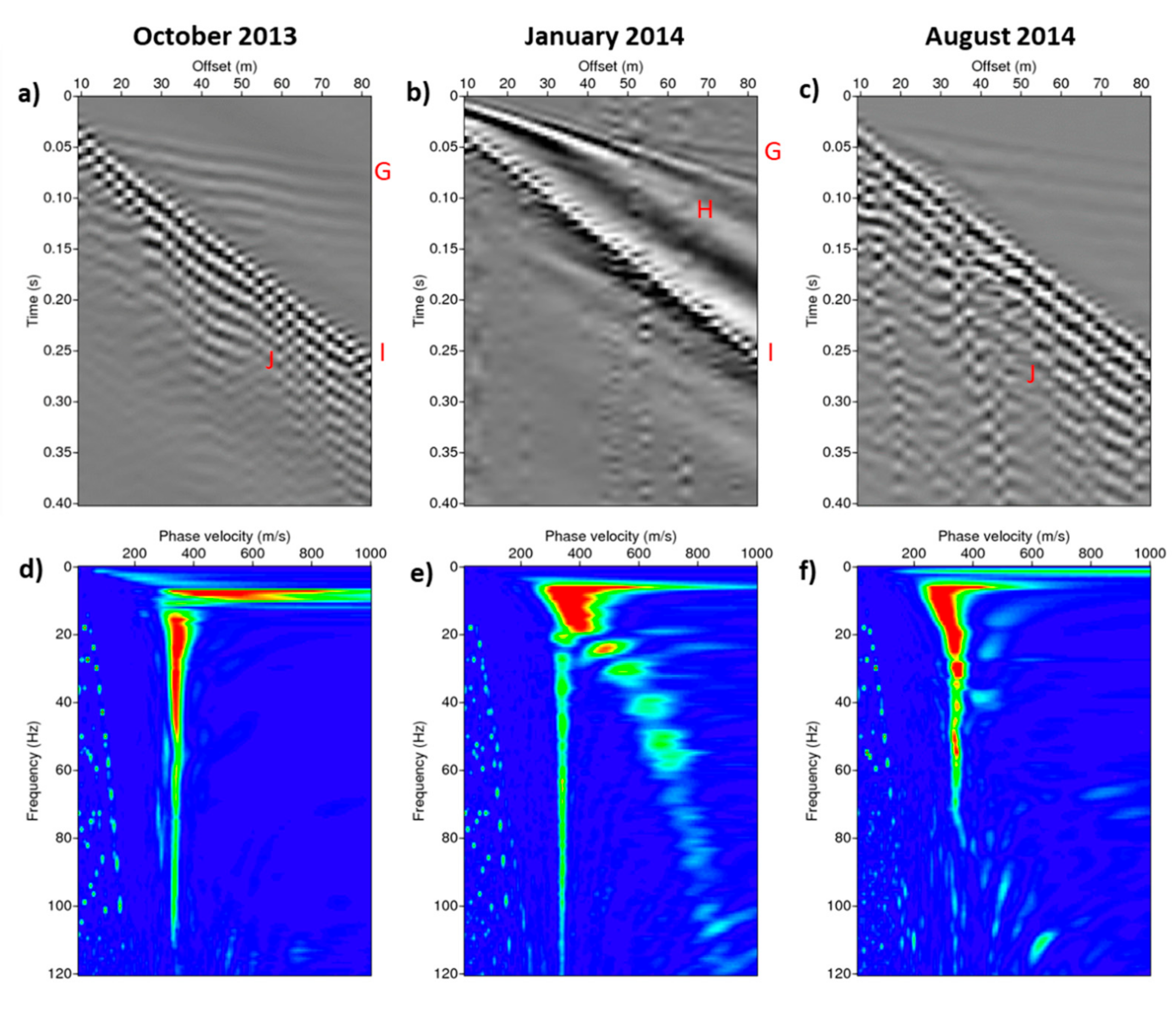
3.2. Real Seismic Data Example

To further study the effects of thawing and freezing on the seismic wavefield, we conducted three similar seismic experiments on permafrost in Adventdalen on Svalbard in the Norwegian Arctic in October 2013, January 2014, and August 2014. Permafrost in this area typically extends to a depth of around 100 m, and the upper approximately 1.2 m is the active layer that thaws seasonally [1]. There are several boreholes in the area that indicate that the upper approximately 2–3 m of sediments in Adventdalen are eolian with a lower salinity than the deeper sediments of marine origin that extend down to the bedrock at approximately 65 m depth. However, these boreholes were drilled with the objective of obtaining information about the deeper bedrock, and thus lack detailed information about the near-surface soil properties, such as saturation, salinity, and porosity [42]. Gilbert, et al. [43] studied several cores acquired throughout Adventdalen and showed that the near-surface geology is somewhat laterally homogenous in the area, but with some local variations. Temperature measurements from a borehole near the study site show that when the experiments were conducted in October, the surface temperature had been fluctuating around 0   for a couple of weeks. In January, surface temperature had been subzero since October (average surface temperature −9.81   ), while in August, the surface temperature had been stable above zero since mid-May (average surface temperature 0.47   ). From this, we presume that ice saturation in the ground was highest in January and lowest in August. We also assume that the ice saturation was more laterally heterogeneous in October than during the other two experiments because the temperatures were close to the freezing point in the weeks prior to this experiment. The soil may also have varied laterally, but this should not affect the time-lapse effect observed in the data, since all three experiments were conducted at the same location.
The objective of the experiments was to acquire reflected, refracted, and surface waves, and we therefore used gimballed geophone strings as seismic receivers in all experiments. Each geophone string consisted of 8 geophones spread out over an interval of 2.5 m, which was also the group interval. Geophone strings reduce the effect of the ground roll (Rayleigh wave), and the actual group length is critical for acquiring surface waves. The array response dampens the ground roll at wavelengths equal to or shorter than the group length, but this effect rapidly decreases for longer wavelengths (lower frequencies). Figure 5 shows that for the seismic setup applied here, we get half of the full response already at around 80 Hz (4 m wavelength) for the air wave traveling at 330 m/s, and the quality improves rapidly with decreasing frequency (increasing wavelength). Therefore, we limit our study to frequencies <100 Hz, where the surface waves should be minorly filtered due to the geophone group length.
The seismic source was firecrackers placed in a 0.2–0.3 m deep hole in the ground. These create an impulsive source signature. The receivers were placed along a 75 m long straight line, with the first receiver 9.5 m from the shot point. Figure 6 shows the location of the study site, and a picture of the seismic spread in October 2013. As the picture and topographic map reveals, the ground below the seismic line was flat, and thus no topography effects were assumed.
Since we lack information about the exact near-surface soil properties and the corresponding elastic properties at the study site, it is not possible to compute theoretical modal curves for these data. However, since we know that salinity is assumed to increase with depth in this area, this implies that the upper sediments freeze at a higher temperature than the deeper sediments due to the freezing point depression in saline pore water. When temperatures decrease gradually with depth, like in the synthetic example, a few possible scenarios are likely: the first is that during summer, we have an irregular velocity gradient in Adventdalen: a thawed upper low velocity layer above a largely frozen low-salinity and high velocity layer, above a less frozen high-salinity and lower velocity layer. A second possibility is that temperatures are high enough during summer so that the low-salinity layer completely thaws, which implies an increasing velocity gradient with depth: a thawed low-salinity and low velocity layer above a partly frozen high-salinity and higher velocity layer. This implies a similar velocity gradient as seen for the synthetic data example. During winter, it is likely that the uppermost low velocity layer disappears, i.e., velocity decreases with depth.
Figure 7a–c show seismic gathers obtained from the three seismic experiments. The data from January are clearly of different nature to the other two gathers, while the differences between the data from October and August are more subtle. A weak event (G) can be seen in all gathers. This is most likely a refraction or reflection from the underlying stiff, consolidated sediments at approximately 65 m depth. The ringing nature of this event seen in the gathers from October and August is probably due to related multiples. Event H in the January data is the Rayleigh wave caused by the frozen, stiff near-surface sediments. The air wave is defined by event I in all gathers. The lack of distinct Rayleigh waves in the data from October and August reveals that the surface sediments are soft. As noted by [44], there could be a strong coupling between the air wave and Rayleigh waves when the upper soil layer supports surface waves with a phase velocity identical to that of the air wave. This requires a soil layer with an S-wave velocity less than 330 m/s at the surface and increasing with depth. The surface waves in the August and October data make a monochromatic wave train (J), which is further indicative of a group velocity lower than phase velocity. This is typical for Rayleigh waves when Vs is increasing with depth (i.e., phase velocity decreasing with increasing frequency).
Figure 7d–f show the corresponding FV-spectra for the three seismic experiments. The energy peak in all spectra is related to the air wave, with a velocity of about 330 m/s, but other events are also seen to vary between the different spectra. The most prominent events are observed in the data from January, where there are several strong amplitude events at increasing phase velocities with increasing frequency. This inversely dispersive trend is probably linked to several higher modes of surface waves, and they are absent in data from October and August. For the August data, some weak events seem to resemble those seen for the synthetic seismic models T1 and T3 at frequencies below 40 Hz. Thus, both the seismic gathers and the FV-spectra show changes in the freezing conditions between the experiments, specifically from January to October and August.

4. Discussion and Conclusions

Both the modeled and the real seismic data reveal that thawing has a significant impact on the seismic wavefield. Seismic properties depend on the ice saturation. Increased surface temperature causes increased heat flux, thawing, and lower seismic velocities of near-surface sediments. The largest change in seismic properties occurs at shallow depths when the surface temperature is high, because this implies the largest heat flux. Since Rayleigh waves are not inherently dispersive, surface wave dispersion means that the elastic properties alter with depth. Correspondingly, thawing or freezing will thus cause temporal changes in the FV-spectra.
In the synthetic seismic data, the fundamental mode of surface wave is dominant for all experiments. Since lower frequencies are more influenced by elastic properties of deeper sediments than higher frequencies, the fundamental mode in the FV-spectra reveals that the seismic velocities in the shallow layers decrease from the T0 to the T1 model and, furthermore, from the T1 to the T3 model. This is consistent with the input data. Since the velocity decrease extends to lower frequencies for T3 than for T1, T3 implies deeper thawing than T1 due to the reduced velocities with increased thawing.
The real seismic data are, as expected, quite different from the modeled seismic data, since the subsurface model used for the synthetic data was not designed to represent local conditions. Since the inversely dispersive trend in the FV-spectra is the strongest in January, weaker in October, and missing in August, this indicates that the presence of higher modes is related to ice saturation. Temperature data indicate that the upper sediments are most frozen in January when the higher modes are strong, and least frozen in August, when the higher modes are absent. Surface waves are generally attenuated more in unfrozen ground than in frozen ground, which also explains why more low-frequency surface waves are seen in the data from January.
We did not consider a varying salinity in the synthetic data example, meaning that seismic velocities here increase steadily with depth. At the study site of the real seismic data, the ground salinity most probably varies with depth, which implies that several velocity depth models are possible. During winter, a stiff upper layer overlies softer sediments, and in this case, strong higher modes are typically generated [14,45,46,47]. This also happens when a low velocity layer is embedded in layers of higher velocities. An analogue to a stiff frozen layer on top of a stack of softer unconsolidated sediments is pavement, which constitutes a thin, very stiff layer overlaying softer sediments. For such velocity depth models, higher order modes of Rayleigh waves have been observed as an inversely dispersive trend in FV-spectra, as well as a large amount of leaky guided waves [48], which are also seen in our synthetic data. During summer, we either have stiffer sediments embedded in softer sediments, or stiffness increasing with depth. For such velocity depth models, higher modes are rarely seen [14,45]. This supports our observation that the fundamental mode is more dominant in October and August, and higher modes are more dominant in January when the uppermost layer is frozen.
Differences in the signatures of the modeled and real seismic data can also be caused by the fact that unlike in the synthetic model, the surface temperature varied frequently between low and high temperatures in the time period between October 2013 and August 2014. Furthermore, variable precipitation throughout the year affects the data. While snow leads to effective insulation of the heat flux, rain alters the moisture content in the uppermost sediments. We also assume a simple horizontally layered geological model, and no lateral soil heterogeneity or anisotropy. Adding complexity to the geological model will certainly affect the seismic data, but will to a lesser degree affect the time-lapse effects in data collected at the same location. The seismic experiments in Adventdalen also included a second seismic data line with the same shot point, but having a 67.5 degree azimuth to the east of the current line. These data display similar FV-spectra and time-lapse effects, indicating gentle variation in the soil properties laterally. The seismic setup of the experiments was not particularly designed for recording surface waves. As full thawing only occurs in the top meter or so in Adventdalen, the receiver interval should in general be minimized to gain more high-frequency data. Although geophone strings were used, the array response retains frequencies up to 100 Hz, which is sufficient for our study.
Our results show significant time-lapse effects in both the seismic gathers and the estimated Rayleigh wave dispersion curves, which can be related to thawing of near-surface Arctic sediments. The synthetic seismic data were made with full control over the physical properties of the models, and show distinct time-lapse effects that are due to changes in the thermal regime. The time-lapse study of the real seismic data strongly indicate that low-frequency time-lapse effect are due to changes in the freezing conditions. Analysis of FV-spectra basically provide trends in the stiffness gradient (increasing/decreasing/irregular). However, to quantify exact changes in the mechanical properties of the subsurface due to thawing requires more sophisticated inversion of FV-spectra to S-wave velocity with depth. Conventional inversion techniques using normal mode methods are not designed for (irregularly) decreasing velocities with depth, or when higher-order modes dominate [45,49,50]. This was seen to occur for the real seismic data example, where higher modes became dominant with increasing frequencies. Full-waveform inversion often works for small modal jumps, but fails for large modal jumps, and where the main energy does not return to the fundamental mode at high frequencies [14,45]. An in-depth discussion or execution of more complex inversion methods is beyond the scope of this study. Our study has been limited to qualitatively assessing the differences between the various seismic gathers and FV-spectra at low frequencies. Our results also highlight the need to know the near-surface soil and pore water properties to estimate the degree of thawing from estimated velocity profiles. The contribution of this study is to demonstrate the potential of using time-lapse surface seismic data in climate monitoring of the terrestrial Arctic.

Author Contributions

Conceptualization, H.M.S. and T.A.J.; Data curation, H.M.S., T.A.J. and B.O.R.; Formal analysis, H.M.S. and B.O.R.; Funding acquisition, T.A.J.; Investigation, H.M.S, T.A.J. and B.O.R.; Methodology, H.M.S, T.A.J. and B.O.R.; Project administration, T.A.J.; Software, H.M.S. and B.O.R.; Supervision, T.A.J.; Validation, H.M.S., T.A.J. and B.O.R.; Visualization, H.M.S. and B.O.R.; Writing—original draft, H.M.S.; Writing—review and editing, H.M.S., T.A.J. and B.O.R. All authors have read and agreed to the published version of the manuscript.

Funding

This research is funded by ARCEx partners and the Research Council of Norway (grant number 228107).

Conflicts of Interest

The authors declare no conflict of interest. The funders had no role in the design of the study; in the collection, analyses, or interpretation of data; in the writing of the manuscript, or in the decision to publish the results.

Appendix A

Hertz–Mindlin contact theory (CT):
Hertz–Mindlin contact theory can be used to compute effective dry rock moduli:
k C T = ( n 2 ( 1     φ 0 ) 2 μ G 2 18 π 2 ( 1     ν G ) 2 P ) 1 3 ,
and:
µ C T = 5 4 ν G 5 2 ν G ( 3 n 2 ( 1     φ 0 ) 2 μ G 2 2 π 2 ( 1     ν G ) 2 P ) 1 3 .
The subscript CT means the effective dry rock moduli and the subscript G means the sediment grain property. k and µ are the bulk and shear modulus, respectively, ν is the Poisson’s ratio, φ0 is the porosity, P is the pressure, and n is the coordination number.
Gassmann fluid substitution (Gassmann, 1951):
Gassmann fluid substitution can be used to compute the effective water-saturated rock properties for a case where the wavelengths >> characteristic pore sizes:
k s a t W = k G φ 0 k C T     1   +   φ 0 k W k C T / k G   +   k W 1     φ 0 k W   +   φ 0 k G     k W k C T / k G .
The subscript satW means the effective fully water-saturated moduli, and the subscript W means water. The shear modulus is unaffected by the presence of a fluid, so:
µ s a t W = µ C T .
Self-consistent approach (SCA) (Berryman (1980a,b)):
The self-consistent approach (SCA) can be used to compute the effective ice-saturated rock properties. The principle of the SCA is to assume inclusions of the constituents in a background medium with initially unknown properties. The strategy is to adjust the elastic properties of the background medium iteratively until the net scattering from a wave incident on the background medium with inclusions is zero. Here, this means setting up two scenarios, j = 1, 2. Scenario 1 is for penny-shaped ice inclusions in a background medium, and scenario 2 is for spherical sediment grain inclusions in a background medium. We compute the elastic moduli kj and µj for each scenario as a function of ice-filled rock effective moduli ksatI and µsatI by using formulas:
k 1 = k i k s a t I S i P i ,
µ 1 = µ i µ s a t I S i Q i ,
k 2 = k g k s a t I S g P g ,
µ 2 = µ g µ s a t I S g Q g .
Si and Sg are the fractions of each inclusion type, and we use shape-dependent factors Pi, Pg, Qi and Qg as found in Dou et al. (2017):
P i = k s a t I   +   4 3 µ i k i   +   4 3 µ i   +   π α i β * ,
Q i = 1 5 1 + 8 µ s a t I 4 µ i + π α i ( µ *   +   2 β * ) + 2 k i   +   2 3 µ i   +   µ s a t I k i   +   4 3 µ i   +   π α i β * ,
P g =   k s a t I   +   4 3 µ s a t I k g   +   4 3 µ s a t I ,
Q g = µ s a t I   +   Ϛ * µ g   +   Ϛ * ,  
where α i is the aspect ratio of the grains, and β * and Ϛ * are defined by:
β * = µ s a t I 3 k s a t I   +   µ s a t I 3 k s a t I   +   4 µ s a t I ,
Ϛ * = µ s a t I 6 9 k s a t I   +   8 µ s a t I k s a t I   +   2 µ s a t I .
We require k1 + k2 = 0 and µ1 + µ2 = 0, and solve these equations iteratively for ksatI and µsatI, which are the ice-filled rock effective elastic moduli.
Modified Hashin–Shtrikman bounds (Hashin and Shtrikman, 1963; Dou et al., 2017):
Hashin–Shtrikman bounds were originally developed to mix two mineral phases. To use Hashin–Shtrikman bounds to mix to fully frozen and fully unfrozen multi-phase composites for estimating elastic properties at varying ice saturations, we replace the volume fraction of each material in the original formulas with the amount of water or ice in the pore space, respectively s w or si (sw+ si = 1 for fully saturated pore space).
Hashin–Shtrikman bounds are upper and lower bounds for elastic moduli: kHS+, kHS, µHS+, and µHS. The effective properties kPF and µPF at any given saturation are simplified as the arithmetic average (Hill average) of these two bounds. The subscript PF means partially frozen.
k P F = 1 2 k H S + + k H S ,
µ P F = 1 2 µ H S + + µ H S ,
where
k H S + = k s a t I + s w k s a t W k s a t I 1 + s i k s a t I + 4 3 µ s a t I 1 ,
k H S = k s a t W + s i k s a t I     k s a t W 1   +   s w k s a t W   +   4 3 µ s a t W 1 ,
µ H S + = µ s a t I + s w µ s a t W     µ s a t I 1   +   2 s i k s a t I   +   2 µ s a t I 5 µ s a t I k s a t I   +   4 3 µ s a t I ,
µ H S = µ s a t W + s i µ s a t I µ s a t W 1   +   2 s w k s a t W   +   2 µ s a t W 5 µ s a t W k s a t W   +   4 3 µ s a t W .

References

  1. Christiansen, H.H.; Etzelmüller, B.; Isaksen, K.; Juliussen, H.; Farbrot, H.; Humlum, O.; Johansson, M.; Ingeman-Nielsen, T.; Kristensen, L.; Hjort, J. The thermal state of permafrost in the Nordic area during the International Polar Year 2007–2009. Permafr. Periglac. Process. 2010, 21, 156–181. [Google Scholar] [CrossRef] [Green Version]
  2. Pachauri, R.K.; Allen, M.R.; Barros, V.R.; Broome, J.; Cramer, W.; Christ, R.; Church, J.A.; Clarke, L.; Dahe, Q.; Dasgupta, P. Climate Change 2014: Synthesis Report. Contribution of Working Groups I, II and III to the Fifth Assessment Report of the Intergovernmental Panel on Climate Change; 9291691437; IPCC: Geneva, Switzerland, 2014. [Google Scholar]
  3. French, H.M. The Periglacial Environment, 5th ed.; John Wiley & Sons: West Sussex, UK, 2017. [Google Scholar]
  4. Hjort, J.; Karjalainen, O.; Aalto, J.; Westermann, S.; Romanovsky, V.E.; Nelson, F.E.; Etzelmüller, B.; Luoto, M. Degrading permafrost puts Arctic infrastructure at risk by mid-century. Nat. Commun. 2018, 9, 5147. [Google Scholar] [CrossRef] [PubMed]
  5. Zimmerman, R.W.; King, M.S. The effect of the extent of freezing on seismic velocities in unconsolidated permafrost. Geophysics 1986, 51, 1285–1290. [Google Scholar] [CrossRef]
  6. Schaefer, K.; Zhang, T.; Bruhwiler, L.; Barrett, A.P. Amount and timing of permafrost carbon release in response to climate warming. Tellus B Chem. Phys. Meteorol. 2011, 63, 168–180. [Google Scholar] [CrossRef]
  7. Kneisel, C.; Hauck, C.; Fortier, R.; Moorman, B. Advances in geophysical methods for permafrost investigations. Permafr. Periglac. Process. 2008, 19, 157–178. [Google Scholar] [CrossRef]
  8. Wu, Y.; Nakagawa, S.; Kneafsey, T.J.; Dafflon, B.; Hubbard, S. Electrical and seismic response of saline permafrost soil during freeze-Thaw transition. J. Appl. Geophys. 2017, 146, 16–26. [Google Scholar] [CrossRef]
  9. Potter, R.W.; Clynne, M.A.; Brown, D.L. Freezing point depression of aqueous sodium chloride solutions. Econ. Geol. 1978, 73, 284–285. [Google Scholar] [CrossRef]
  10. Wu, Y.; Hubbard, S.S.; Ulrich, C.; Wullschleger, S.D. Remote monitoring of freeze–thaw transitions in Arctic soils using the complex resistivity method. Vadose Zone J. 2012, 12, vzj2012.0062. [Google Scholar] [CrossRef]
  11. Dou, S.; Nakagawa, S.; Dreger, D.; Ajo-Franklin, J. A rock-physics investigation of unconsolidated saline permafrost: P-wave properties from laboratory ultrasonic measurements. Geophysics 2016, 81, WA233–WA245. [Google Scholar] [CrossRef]
  12. Johansen, T.A.; Digranes, P.; van Schaack, M.; Lønne, I. Seismic mapping and modeling of near-surface sediments in polar areas. Geophysics 2003, 68, 566–573. [Google Scholar] [CrossRef]
  13. Park, C.B.; Miller, R.D.; Xia, J. Multichannel analysis of surface waves. Geophysics 1999, 64, 800–808. [Google Scholar] [CrossRef] [Green Version]
  14. Dou, S.; Ajo-Franklin, J.B. Full-wavefield inversion of surface waves for mapping embedded low-velocity zones in permafrost. Geophysics 2014, 79, EN107–EN124. [Google Scholar] [CrossRef] [Green Version]
  15. Strobbia, C.; Glushchenko, A.; Laake, A.; Vermeer, P.; Papworth, T.; Ji, Y. Arctic near surface challenges: The point receiver solution to coherent noise and statics. First Break 2009, 27, 69–76. [Google Scholar]
  16. Tsuji, T.; Johansen, T.A.; Ruud, B.O.; Ikeda, T.; Matsuoka, T. Surface-wave analysis for identifying unfrozen zones in subglacial sediments. Geophysics 2012, 77, EN17–EN27. [Google Scholar] [CrossRef]
  17. Ajo-Franklin, J.; Dou, S.; Daley, T.; Freifeld, B.; Robertson, M.; Ulrich, C.; Wood, T.; Eckblaw, I.; Lindsey, N.; Martin, E. Time-lapse surface wave monitoring of permafrost thaw using distributed acoustic sensing and a permanent automated seismic source. In SEG Technical Program Expanded Abstracts 2017; Society of Exploration Geophysicists: Tulsa, OK, USA, 2017; pp. 5223–5227. [Google Scholar]
  18. Romanovsky, V.E.; Osterkamp, T.E. Effects of unfrozen water on heat and mass transport processes in the active layer and permafrost. Permafr. Periglac. Process. 2000, 11, 219–239. [Google Scholar] [CrossRef]
  19. Weismüller, J.; Wollschläger, U.; Boike, J.; Pan, X.; Yu, Q.; Roth, K. Modeling the thermal dynamics of the active layer at two contrasting permafrost sites on Svalbard and on the Tibetan Plateau. Cryosphere 2011, 5, 741–757. [Google Scholar] [CrossRef] [Green Version]
  20. Seneviratne, S.I.; Donat, M.G.; Pitman, A.J.; Knutti, R.; Wilby, R.L. Allowable CO 2 emissions based on regional and impact-related climate targets. Nature 2016, 529, 477. [Google Scholar] [CrossRef] [Green Version]
  21. Govaerts, J.; Beerten, K.; Veen, J.T. Weichselian permafrost depth in the Netherlands: A comprehensive uncertainty and sensitivity analysis. Cryosphere 2016, 10, 2907–2922. [Google Scholar] [CrossRef] [Green Version]
  22. De Vries, D.A. Thermal properties of soils. In Physics of Plant Environment; North-Holland Publishing Corporation: Amsterdam, The Netherlands, 1963; pp. 210–235. [Google Scholar]
  23. Pryor, R.W. Multiphysics Modeling Using COMSOL®: A First Principles Approach, 1st ed.; Jones & Bartlett Publishers: Sudbury, MA, USA, 2009. [Google Scholar]
  24. Mavko, G.; Mukerji, T.; Dvorkin, J. The Rock Physics Handbook, 2nd ed.; Cambridge University Press: New York, NY, USA, 2009. [Google Scholar]
  25. Dvorkin, J.; Nur, A. Elasticity of high-porosity sandstones: Theory for two North Sea data sets. Geophysics 1996, 61, 1363–1370. [Google Scholar] [CrossRef]
  26. Dvorkin, J.; Nur, A.; Yin, H. Effective properties of cemented granular materials. Mech. Mater. 1994, 18, 351–366. [Google Scholar] [CrossRef]
  27. Dvorkin, J.; Berryman, J.; Nur, A. Elastic moduli of cemented sphere packs. Mech. Mater. 1999, 31, 461–469. [Google Scholar] [CrossRef]
  28. Minshull, T.; Singh, S.; Westbrook, G. Seismic velocity structure at a gas hydrate reflector, offshore western Colombia, from full waveform inversion. J. Geophys. Res. Solid Earth 1994, 99, 4715–4734. [Google Scholar] [CrossRef]
  29. Dou, S.; Nakagawa, S.; Dreger, D.; Ajo-Franklin, J. An effective-medium model for P-wave velocities of saturated, unconsolidated saline permafrost. Geophysics 2017, 82, EN33–EN50. [Google Scholar] [CrossRef]
  30. Mindlin, R. Compliance of elastic bodies in contact. J. Appl. Mech. ASME 1949, 16, 259–268. [Google Scholar]
  31. Gassmann, F. Elastic waves through a packing of spheres. Geophysics 1951, 16, 673–685. [Google Scholar] [CrossRef]
  32. Berryman, J.G. Long-wavelength propagation in composite elastic media II: Ellipsoidal inclusions. J. Acoust. Soc. Am. 1980, 68, 1820–1831. [Google Scholar] [CrossRef]
  33. Berryman, J.G. Long-wavelength propagation in composite elastic media I: Spherical inclusions. J. Acoust. Soc. Am. 1980, 68, 1809–1819. [Google Scholar] [CrossRef]
  34. Hashin, Z.; Shtrikman, S. A variational approach to the theory of the elastic behaviour of multiphase materials. J. Mech. Phys. Solids 1963, 11, 127–140. [Google Scholar] [CrossRef]
  35. Stemland, H.M.; Johansen, T.A.; Ruud, B.O.; Mavko, G. Elastic properties as indicators of heat flux into cold near-surface arctic sediments. Geophysics. under review.
  36. Landau, L.D.; Kosevich, A.; Pitaevskii, L.P.; Lifshitz, E.M. Theory of Elasticity, 3rd ed.; Butterworth-Heinemann: Oxford, UK, 2012. [Google Scholar]
  37. Zhang, S.X.; Chan, L.S.; Chen, C.Y.; Dai, F.C.; Shen, X.K.; Zhong, H. Apparent phase velocities and fundamental-mode phase velocities of Rayleigh waves. Soil Dyn. Earthq. Eng. 2003, 23, 563–569. [Google Scholar] [CrossRef]
  38. Pan, Y.; Xia, J.; Gao, L.; Shen, C.; Zeng, C. Calculation of Rayleigh-wave phase velocities due to models with a high-velocity surface layer. J. Appl. Geophys. 2013, 96, 1–6. [Google Scholar] [CrossRef]
  39. Park, C.B.; Miller, R.D.; Xia, J. Imaging dispersion curves of surface waves on multi-channel record. In SEG Technical Program Expanded Abstracts 1998; Society of Exploration Geophysicists: Tulsa, OK, USA, 1998; pp. 1377–1380. [Google Scholar]
  40. Schmidt, H.; Jensen, F.B. A full wave solution for propagation in multilayered viscoelastic media with application to Gaussian beam reflection at fluid–solid interfaces. J. Acoust. Soc. Am. 1985, 77, 813–825. [Google Scholar] [CrossRef]
  41. Herrmann, R.B. Computer programs in seismology: An evolving tool for instruction and research. Seismol. Res. Lett. 2013, 84, 1081–1088. [Google Scholar] [CrossRef]
  42. Braathen, A.; Bælum, K.; Christiansen, H.H.; Dahl, T.; Eiken, O.; Elvebakk, H.; Hansen, F.; Hanssen, T.H.; Jochmann, M.; Johansen, T.A. The Longyearbyen CO 2 Lab of Svalbard, Norway—Initial assessment of the geological conditions for CO2 sequestration. Nor. J. Geol. Nor. Geol. Foren. 2012, 92, 353–376. [Google Scholar]
  43. Gilbert, G.L.; O‘Neill, H.B.; Nemec, W.; Thiel, C.; Christiansen, H.H.; Buylaert, J.P. Late Quaternary sedimentation and permafrost development in a Svalbard fjord-valley, Norwegian high Arctic. Sedimentology 2018, 65, 2531–2558. [Google Scholar] [CrossRef]
  44. Haskell, N.A. A note on air-coupled surface waves. Bull. Seismol. Soc. Am. 1951, 41, 295–300. [Google Scholar]
  45. O‘Neill, A.; Matsuoka, T. Dominant higher surface-wave modes and possible inversion pitfalls. J. Environ. Eng. Geophys. 2005, 10, 185–201. [Google Scholar] [CrossRef]
  46. Tokimatsu, K.; Tamura, S.; Kojima, H. Effects of multiple modes on Rayleigh wave dispersion characteristics. J. Geotech. Eng. 1992, 118, 1529–1543. [Google Scholar] [CrossRef]
  47. Lu, L.; Wang, C.; Zhang, B. Inversion of multimode Rayleigh waves in the presence of a low-velocity layer: Numerical and laboratory study. Geophys. J. Int. 2007, 168, 1235–1246. [Google Scholar] [CrossRef] [Green Version]
  48. Ryden, N.; Lowe, M.J. Guided wave propagation in three-layer pavement structures. J. Acoust. Soc. Am. 2004, 116, 2902–2913. [Google Scholar] [CrossRef]
  49. Xia, J.; Miller, R.D.; Park, C.B.; Tian, G. Inversion of high frequency surface waves with fundamental and higher modes. J. Appl. Geophys. 2003, 52, 45–57. [Google Scholar] [CrossRef]
  50. Zhang, S.X.; Chan, L.S. Possible effects of misidentified mode number on Rayleigh wave inversion. J. Appl. Geophys. 2003, 53, 17–29. [Google Scholar] [CrossRef]
Figure 1. Freezing point isotherm throughout four years for (a) high porosity sand, and (b) low porosity sand. Both models are displayed for low salinity (dashed lines, freezing point temperature is −0.17 °C) and high salinity (solid lines, freezing point temperature is −1.43 °C ) pore water, and for models T1 (top boundary temperature = +1 °C ), T2 (top boundary temperature = +5 °C ), and T3 (top boundary temperature = +10 °C ).
Applsci 10 01875 g001
Figure 2. Variation in temperature and seismic velocities with time throughout four years at two stationary points for the models T1 (top boundary temperature = +1 °C), T2 (top boundary temperature = +5 °C ), and T3 (top boundary temperature = +10 °C ): (a) temperature at 2 m depth, (b) P-wave velocity at 2 m depth, (c) S-wave velocity at 2 m depth, (d) temperature at 10 m depth, (e) P-wave velocity at 10 m depth, (f) S-wave velocity at 10 m depth. Note the different axis scales for the two depths. The velocity decrease for all models is caused by the decreasing ice saturation due to temperature increase.
Applsci 10 01875 g002
Figure 3. Variation in temperature and seismic velocities with depth for a specific point in time (after four years) for models T0 (initial model, −5 °C through the column), T1 (top boundary temperature = +1 °C), and T3 (top boundary temperature = +10 °C). (a) Temperature profiles, (b) P-wave velocity profiles, and (c) S-wave velocity profiles. Temperature is equal at all depths for T0, so the observed velocity variation with depth is only due to the porosity decrease: 40% in the upper layer, 35% in the second layer, 30% in the third layer, and 20% in the bottom layer.
Applsci 10 01875 g003
Figure 4. Top: synthetic seismic gathers for (a) model T0 (initial model, −5 °C through the column), (b) model T1 (top boundary temperature = +1 °C ), and (c) model T3 (top boundary temperature = +10 °C). Bottom: corresponding frequency-phase velocity spectra (FV-spectra) with theoretical modal curves computed from the input models overlaid for (d) model T0, (e) model T1, and (f) model T3. The traces are plotted with an Ormsby-filter (1–25–40–120 Hz) to enhance the low frequencies and reduce aliasing. The capital letters A–F indicate the various modes of surface waves: A, C, and E is the fundamental mode, and D and F is the first higher mode.
Applsci 10 01875 g004
Figure 5. The array response of geophone strings with eight geophones where the length and group intervals are 2.5 m. The colors represent the gain of using the array relative to using a single geophone. Using geophone groups significantly downgrades the quality of the surface wave data at high frequencies, but affects in a minor way the amplitudes at low frequencies, except for at very low phase velocities.
Applsci 10 01875 g005
Figure 6. The location of the real seismic experiments in Adventdalen on Svalbard in the Norwegian Arctic is marked with a red dot in the small topographic map. The picture shows the study site in October 2013. Gimballed geophone strings are laid out with a 2.5 m group interval. Maps courtesy of Norwegian Polar Institute.
Applsci 10 01875 g006
Figure 7. Top: seismic gathers acquired in Adventdalen in (a) October 2013, (b) January 2014, and (c) August 2014. Bottom: corresponding FV-spectra for (d) October 2013, (e) January 2014, and (f) August 2014. The capital letters G-J identify various wave modes.
Applsci 10 01875 g007

