Article

Three-Dimensional CAD in Skull Reconstruction: A Narrative Review with Focus on Cranioplasty and Its Potential Relevance to Brain Sciences

1
Department of Exercise and Health Promotion, College of Education, Chinese Culture University, Taipei 11114, Taiwan
2
Division of Neurosurgery, Department of Surgery, Kuang Tien General Hospital, Taichung 43303, Taiwan
3
Department of Biotechnology and Animal Science, College of Bioresources, National Ilan University, Yilan 26047, Taiwan
4
Department of Biotechnology, College of Medical and Health Care, Hung Kuang University, Taichung 43302, Taiwan
5
Department of Health Business Administration, College of Medical and Health Care, Hung Kuang University, Taichung 43302, Taiwan
*
Author to whom correspondence should be addressed.
Appl. Sci. 2020, 10(5), 1847; https://doi.org/10.3390/app10051847
Submission received: 31 December 2019 / Revised: 26 February 2020 / Accepted: 4 March 2020 / Published: 7 March 2020
(This article belongs to the Special Issue Computer-aided Biomedical Imaging 2020: Advances and Prospects)

Abstract

:
In patients suffering from severe traumatic brain injury and massive stroke (hemorrhagic or ischemic), decompressive craniectomy (DC) is a surgical strategy used to reduce intracranial pressure, and to prevent brainstem compromise from subsequent brain edema. In surviving patients, cranioplasty surgery helps to protect brain tissue, and correct the external deformity. The aesthetic outcome of cranioplasty using an asymmetrical implant can negatively influence patients physically and mentally, especially young patients. Advancements in the development of biomaterials have now made three-dimensional (3-D) computer-assisted design/manufacturing (CAD/CAM)-fabricated implants an optimal choice for the repair of skull defects following DC. Here, we summarize the various materials for cranioplasty, including xenogeneic, autogenous, and alloplastic grafts. The processing procedures of the CAD/CAM technique are briefly outlined, and reflected our experiences to reconstruct skull CAD models using commercial software, published previously, to assess aesthetic outcomes of regular 3-D CAD models without contouring elevation or depression. The establishment of a 3-D CAD model ensures a possibility for better aesthetic outcomes of CAM-derived alloplastic implants. Finally, clinical consideration of the CAD algorithms for adjusting contours and their potential application in prospective healthcare are briefly outlined.

1. Introduction

The following important vital structures are contained in the unchanged volume of solid skull bone: (1) the brain, as the most important and complex organ, (2) blood, which flows through the arteries and veins, and (3) cerebrospinal fluid (CSF) (Monro–Kellie doctrine). Under critical circumstances, such as a severe traumatic brain injury and massive stroke (hemorrhagic or ischemic), primary insults to the brain tissues cause disrupted osmolite transport, disturbed transendothelial sodium gradient, enhanced oxidative stress, and augmented inflammatory cascade, thereby triggering devastating impaired permeability of the blood–brain barrier and abnormal accumulation of water within the brain tissue [1,2]. The aforementioned secondary injuries exaggerate various forms of brain edema, including cytotoxic, ionic, and vasogenic [3,4], and result in the consequent brain swelling. Within a fixed cranial vault, such injury-triggered brain swelling would unstoppably cause an increase in intracranial pressure (ICP), decreased cerebral blood flow, and attenuated oxygen supply to brain, bringing further deterioration of the brain edema. As a vicious pathological cycle, sustained brain swelling may eventually cause brainstem compromise, and leads to life-threatening complications [5].

2. Rationale to Remove (Decompressive Craniectomy) and Replace (Cranioplasty) the Skull Bone

Within the cranial skull, injury-driven brain swelling will result in the compromise of intracranial blood flow, and, as a consequence of Monro–Kellie doctrine, cause ischemic and hypoxic changes of brain tissues [6], which promotes further brainstem injuries. During critical neurological conditions with underlying profound brain swelling, decompressive craniectomy (DC) is a kind of surgical procedure that needs urgent implementation to reflect the skull bone, open the dura, remove the pathological lesions (i.e., hematoma), and augment the dural covering of the brain [7,8]. As early as 1901, Kocher filed the first case report of DC [9]. DC is performed to augment intracranial space, facilitate outward expanding of an injury-driven swollen brain, and accommodate the additional brain volume, thereby preventing the compromise of the brainstem [10,11]. DC has been proven to attenuate ICP levels, increase blood flow, and augment tissue oxygen tension of brain tissues, which consequently improves long-term outcomes [11,12,13].
In some patients with skull defects following DC procedures, particularly the elderly, a flattened or sunken skin flap can be presented, resulting in a neurological deterioration (i.e., trephined syndrome) [14]. Progressive sinking of the skin flap can induce intracranial compromise, which impairs cerebral autoregulation and haemodynamics [15,16]. Cranioplasty is a surgical procedure that reconstructs a skull defect, thereby protecting the contents of the skull against atmospheric pressure. Cranioplasty has been shown to benefit the restoration of cerebral vital structures, recovery of the curvature of the scalp flap, and therefore the expansion of brain tissues and clinical improvements [14,17]. The optimal time frame for cranioplasty in patients with skull defects has been shown to be within a 0- to 3-month interval after the initial DC surgery. Reduced risks of complications, such as disrupted CSF dynamics, impaired brain perfusion, and even trephined syndrome, have been presented in reports of a shorter interval time frame for cranioplasty, when compared to a greater than 6-month interval after the initial surgery [18].

3. Brief Outline of Materials Used for Cranioplasty

Cranioplasty has been recorded in human history as early as 3000 B.C. Across the centuries, materials used in cranioplasty can be classified into the following three categories [19]: (1) xenogeneic grafts: bone from non-human donors (oxen horn, eagle bone, hare bone, soup-bone cranioplasty (cooked shoulder of a sheep, 1917), coconut shells, palm leaves. (2) Autogenous grafts: rib, sternum, tibia, skull. (3) Alloplastic grafts: metals (aluminum, gold, cobalt-chromium, tantalum, titanium, alloys, stainless steel), biosynthetic materials such as acrylic resins or polymethyl methacrylate (PMMA), and ceramics (hydroxyapatite). Cranioplasty with xenogeneic materials is more primitive, after all, and the overall outcome is unsatisfactory. Furthermore, bone resorption and the consequent unsatisfactory cosmetic outcome are common disadvantages of implants with autogenous bone grafts. Recently, titanium and PMMA have become the main feasible alternatives for skull defect reconstruction.
Hydroxyapatite is a ceramic material, and can augment bone formation. Impaired malleability and a high infection rate (2.6%–10%) are the clinical concerns in the use of hydroxyapatite [20,21,22]. PMMA is one of the most common alloplastic materials in cranioplasty because of its low cost and easy availability. PMMA cranioplasty has been shown to be associated with a longer operative time for contour molding, greater blood loss, and high infection rate (4%–13.8%) [21,23,24,25]. Titanium mesh was used during the Vietnam War to repair craniofacial defects. Advantages of titanium mesh applied in cranioplasty include the following: strength, low molecular weight, low thermal conductivity, elasticity similar to bone, magnetic resonance imaging (MRI) and computed tomography (CT) compatibility, and a relatively low infection rate (0%–4.5%) [17,23,24]. The role of titanium mesh in craniofacial reconstruction has been established and the applications have been shown as follows: craniofacial repairment including mandibular, maxillary, zygomatic, orbital, and calvarial reconstruction, head trauma, sinus fractures, battle wounds, repair after surgical removal of meningiomas, skull base tumors, cerebral infarction, herpes encephalitis, and brain abscess [26].

4. Aesthetics of Cranioplasty—Not Solely Limited to the Function of Bone Replacement

Cranioplasty should have two implications. In addition to protecting brain tissue, it also helps to correct deformity in appearance. The optimal material for cranioplasty is autogenous bone from the original skull, but in many cases, osteolysis or infection may reduce its applicability. As high as from 2.7% to 51% of bone resorption rate has been shown [27,28,29,30]. Approximately a 2.7% bone resorption rate per year has been presented following a longer follow-up period [31]. Resorption of autogenous bone from the native skull gradually causes disfigurement in general appearance. The patients who survive their injury events, however, must endure cranial deformity, unless a reconstructive surgery can be aesthetically undertaken. The gross external appearance of the skull after craniectomy negatively affects patients physically and mentally, especially young patients who are concerned about their appearance.
The three-dimensional (3-D) computer-assisted design (CAD) contouring method is not likely to be applied in all alloplastic materials, such as PMMA. The contour molding during cranioplasty surgery tends to be time-consuming, and inferior aesthetic cosmesis has been shown compared to computer-assisted reconstructive strategy [32,33,34]. Attempts have been made to semiquantitativly determine the raised height of skull defects in PMMA cranioplasty [35]. Some successes have been addressed in computer-assisted design/manufacturing (CAD/CAM) of 3-D titanium mesh implants for the reconstruction of skull defects of large-area hemi-skull bones and frontal bones, with excellent results [7,26,36].

5. Three-Dimensional CAD/CAM Models in the Reconstruction of Skull Defects

Advancements in the development of CAD/CAM techniques have now made CAD/CAM-generated devices a new option in orthopedic surgery, maxillofacial, and dental reconstruction. Through rapid prototyping techniques, more accurate manufacturing of custom-made medical implants can be achieved in subspecialties in dentistry, including restorative dentistry, prosthetic dentistry, and orthodontics [37,38]. The application of CAD/CAM technology has been addressed in the fabrication of maxillofacial and orthopedic prostheses, such as artificial ear [39] and congenital heart disease [40] to plan preoperatively or simulate surgery intraoperatively. Herein, we focus on the application of CAD/CAM technology in cranioplasty.
During specific circumstances, such as fracture and resorption of the original bone flap, or unsatisfying shape of the artificial skull, CAD/CAM-fabricated implants in cranioplasty can be a suitable option. In skull defect reconstruction, CAD/CAM techniques include the designing of a CAD model and computer-based processing to manufacture custom-made skull implants from alloplastic materials indicated with 3-D contouring, such as titanium and PMMA. Advantages have been shown in accumulating the literature to apply 3-D CAD implants for craniofacial skeletal reconstruction in terms of excellent cosmesis and few complications when compared to autogenous or alloplastic bone grafts in cranioplasty and facial reconstructive surgeries [21,23,41,42]. We present an overview of the processing and analysis of CAD modeling for the reconstruction of defective skulls. The flow of processing methods of the CAD/CAM technique and potential perspectives of CAD modeling in brain sciences are shown in Figure 1.

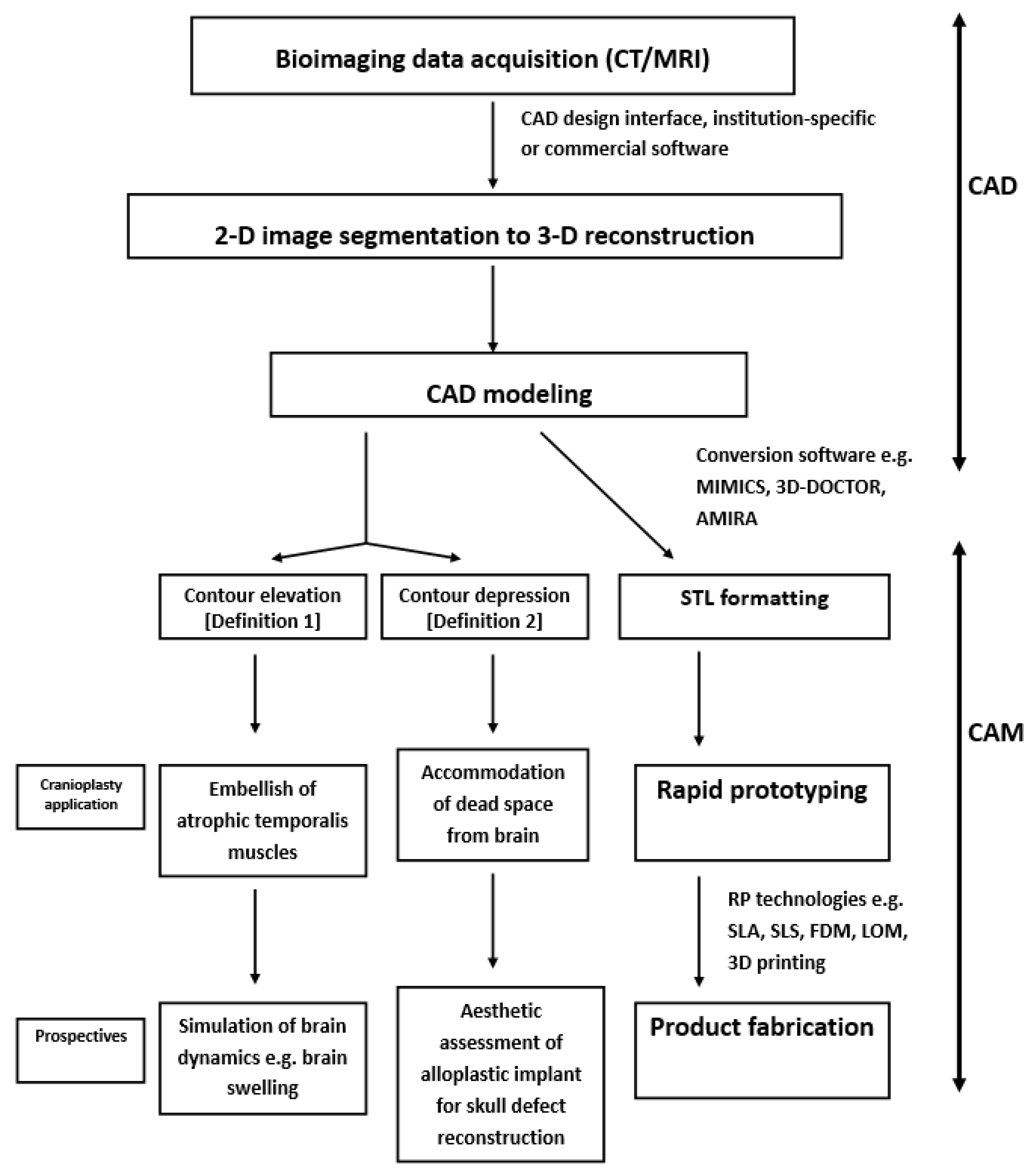
6. Brief Overview of the CAD Modeling Process for the Reconstruction of Cranial Defects

In general, image data are captured from the bioimaging of CT scans for the design of a CAD model of skull defect reconstruction. The patients with skull defects will receive CT scans of the brain with slice thickness from the skull base to convexity, including the region of the skull defect. It is understood that a high-resolution CT scan represents a slice as thin as 1–2 mm. A 1.25 mm thick of CT slice has been shown for a 3-D titanium mesh reconstruction of a defective skull [26].
Advances in hardware and software have increased the feasibility of accurate 3-D CAD reconstruction of skull skeletons [12,13,14]. The two-dimensional (2-D) images of brain CT scans can be edited with medical institution-specific or commercial software. As shown in Figure 2B,D,F, and Figure 3G,I,L, by using an image-editing interface approach to process the CT digital information, the contour of the skull defect can be manually reconstructed under the CT bone window image. The image-editing interface provides a region-growing function to reconstruct the flap and the original cranial skull [43], so that the external appearance and symmetry of the CAD model can therefore be verified. Specifically, the symmetry of the reconstructed 3-D artificial CAD flap will be simultaneously evaluated via axial, coronal, and sagittal views (as shown in Figure 2C,E,G and Figure 3H,J,K,M).

7. Demonstration of Editing the 2-D Images of Brain CT Scans Using Commercial Software

Various commercial software can be used to reconstruct skull CAD models. For example, Open Source Computer Vision (OpenCV), Open Graphic Library (OpenGL) OBJ Viewer, and GLC Player, etc. Some of the commercial 3-D software are easily available and can even be downloaded for free. An investigation has previously addressed the editing method of the 2-D images of brain CT scans using OpenCV and OpenGL OBJ Viewer [44].
In brief, CT bone window images with a JPEG file format are first loaded into OpenCV interface. The user next identifies and previews the axis of symmetry of the skull in the CT bone window image. Once the axis of symmetry has been established, the symmetrical contour to fill the skull defect will be defined by the software, based on the axis of symmetry and the contralateral skull curvature. Redundant contours outside the skull defect can be further modified subjectively with an unsymmetrical skull.
A 3-D model of the reconstruction of the skull defect can be established using the interface of OpenGL OBJ Viewer. The points surrounding the contour in each CT bone window image needed to be extracted, followed by forming triangles via the connections of the adjacent points. The interpreted formula can be briefly summarized as follows.
Assume:
  • PD surrounding points in image D,
    PD+1 surrounding points in image D + 1,
    Adjacent point in image D + 1 of the sth point in image L is the (s* PD + 1 /PD)th point in image D + 1.
    Let n = (s*PD + 1 /PD), for the sth point in image D, triangles are formed by connecting
    the sth and (s + 1)th points in image D and the nth point in image D + 1
    the (s + 1)th point in image D and the nth and (n + 1)th points in image D + 1
Following the formation of two triangles for each point in each image, all triangles surrounding the surface of the skull will be eventually generated.
In general, the aesthetic outcomes of the CAM-derived alloplastic implant for repair of skull defect can be enhanced through the fabrication process from a CAD model of defect reconstruction that is symmetrical to the curvature of the contralateral skull. Thus, the determination of a symmetrically regular CAD skull model (without elevated or depressed contouring) is quite important. An example of the quantitative assessment of the regular CAD model can be found in terms of cranial index of symmetry (CIS) (CIS > 95% indicating symmetry [45]). Results show the CIS scores of 15 CAD models derived from commercial software (OpenCV and OpenGL OBJ Viewer) were 99.24 + 0.004% (range 98.47–99.84) [44].

8. Brief Overview of CAM Processing for Reconstruction of Cranial Defects

Through CAD/CAM procedures, the CAD data will next be transferred to CAM processing. In brief, the CAD information has to be first converted into STL formatting. The following software have been shown to be helpful in the conversion—MIMICS, 3D-Doctor, SliceOmatic, and AMIRA [46]. CAD data will be processed using the rapid prototyping technique, and a CAD/CAM-fabricated implant can be eventually stamp-molded. Modeling for rapid prototyping can be conducted through the following processes: SLA (stereo lithography), SLS (selective laser sintering), LOM (laminated object manufacturing), FDM (fused deposition modeling), and novel 3-D printing [43].

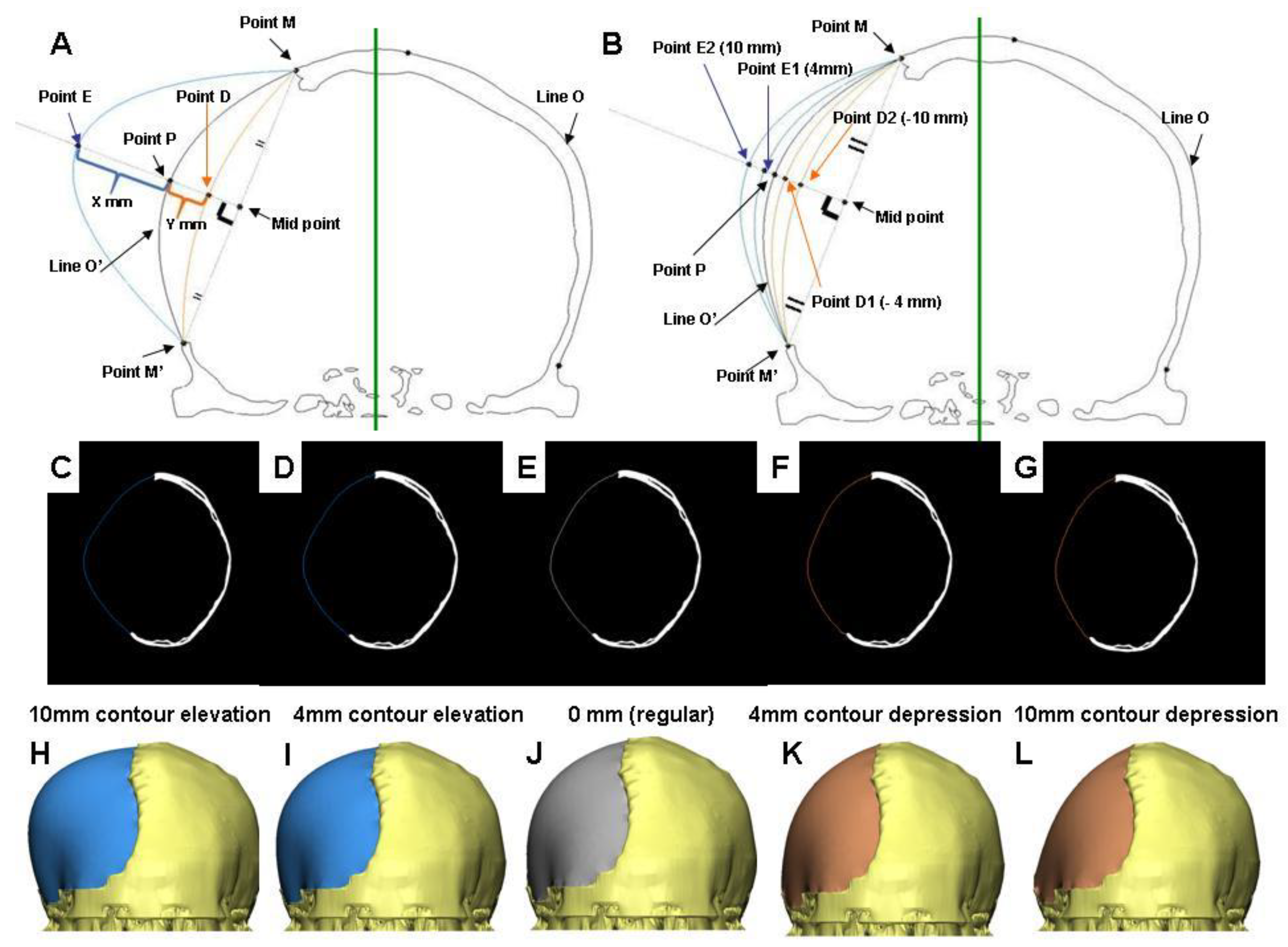
9. Clinical Consideration of CAD Algorithms for Adjusting Contours

In some circumstances, the CAD algorithms for the contouring of skull defects are likely to be adjusted, either in elevation or depression. In patients with resorption of the autogenous bone grafts or atrophy of the temporalis muscle, newly reconstructed contours should be elevated to compensate for the depressed curvature of soft tissue bulk and deficits of the temporalis muscle [42].
Thin and flattened skin flaps can be found in the elderly or patients with trephined syndrome. Difficulties in scalp adaptation during cranioplasty surgery are likely to take place in these patients. Difficult scalp adaptation can cause impaired tension-free skin closure and subsequent skin necrosis. Furthermore, a dead space between the scalp and dura can be created if parts of the brain have been removed during the initial decompressive surgery. For the aforementioned conditions, the newly reconstructed contour should be depressed to prevent excessive tension to the scalp, and avoid enlargement of the dead space between the dura and implant.
Thus, smaller or larger CAD/CAM-fabricated implants are likely applied in cranioplasty surgeries under various clinical circumstances. We herein emphasize the significance of the establishment of accurate and symmetrical regular CAD models before adjusting the CAD contours.

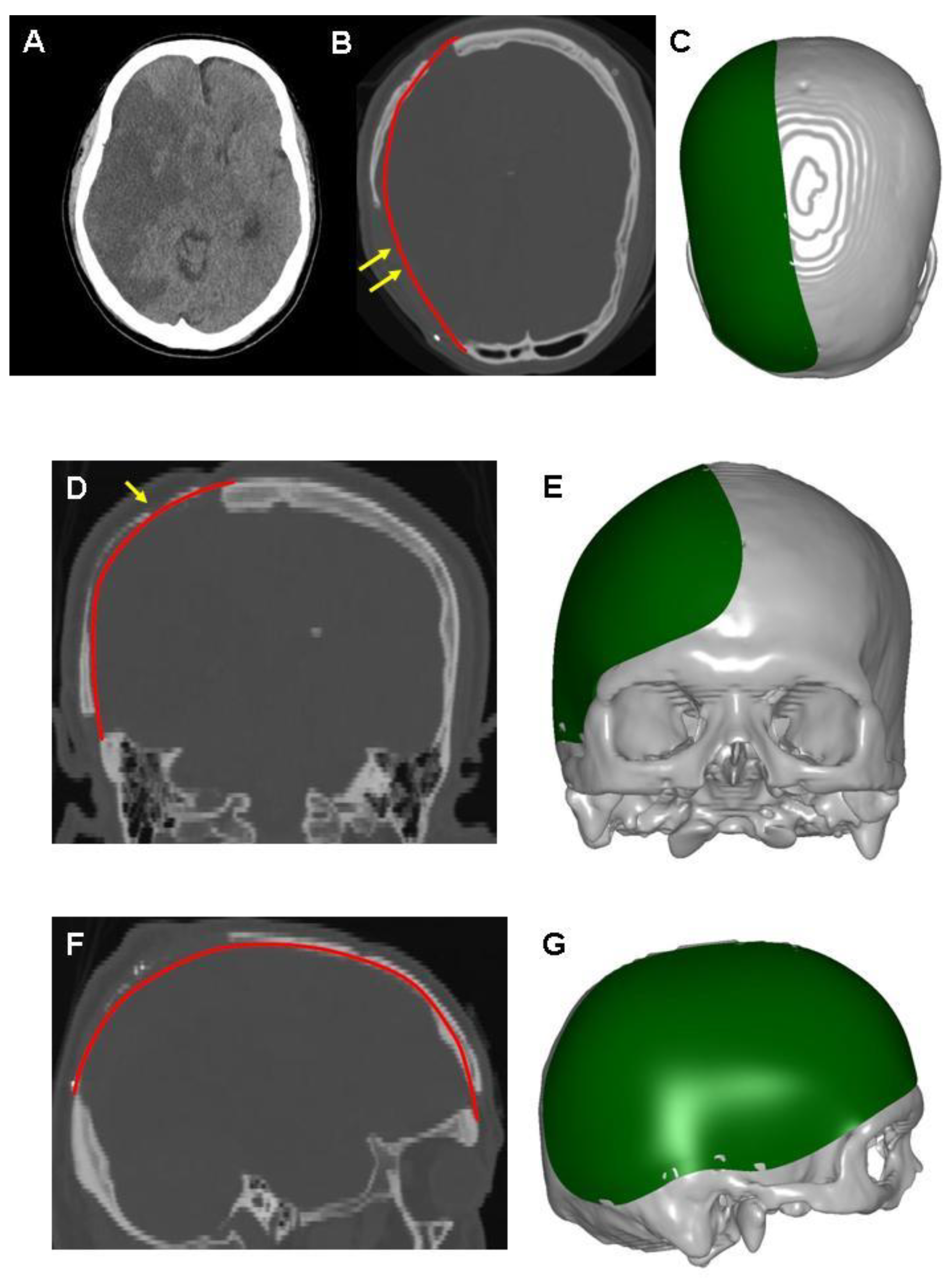
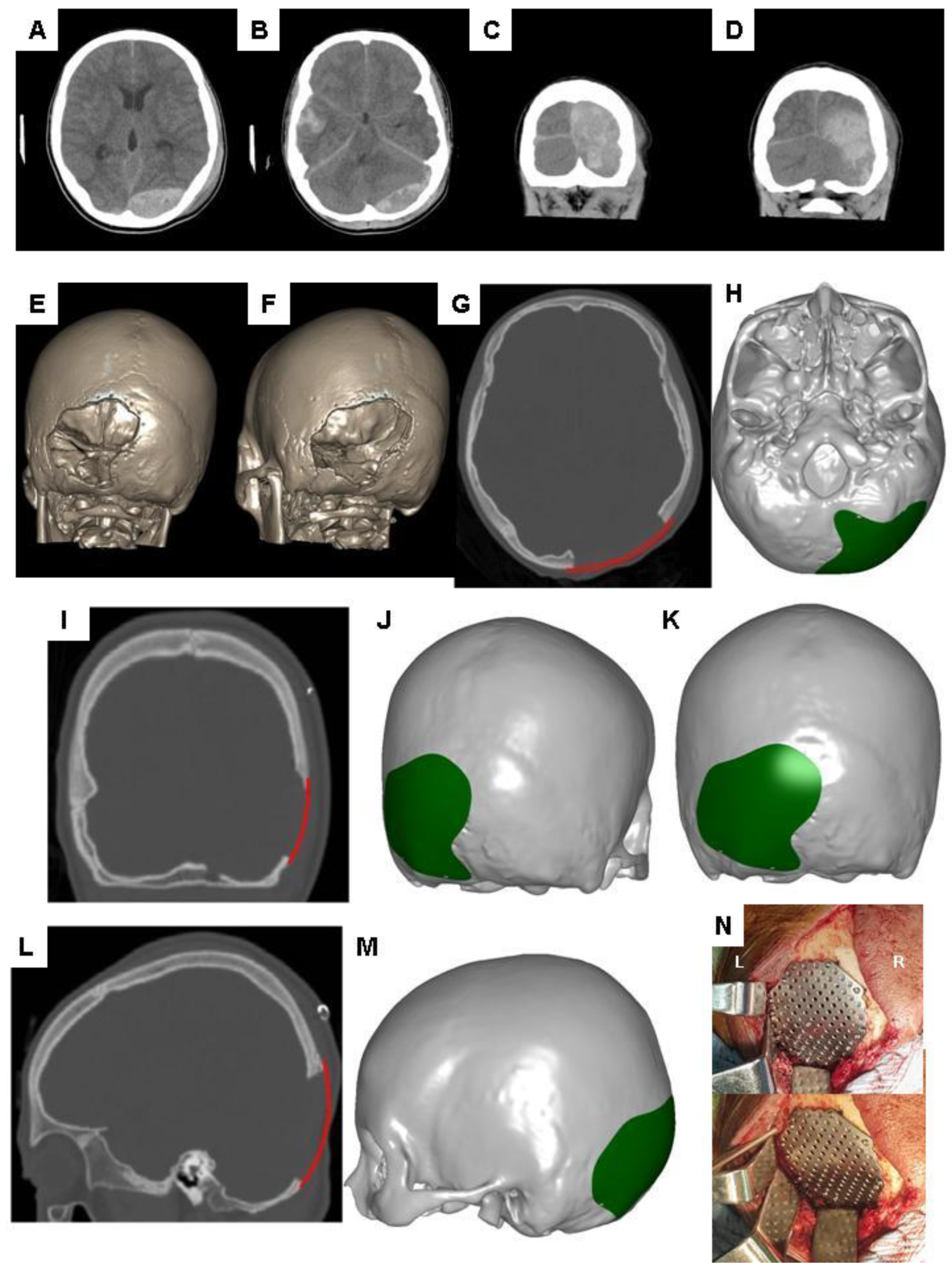
10. Demonstration of Adjusting Contours for the Reconstruction of Skull Defects in CAD Modeling

As shown in Figure 4A, we present a schematic planning of the contour reconstruction of a demonstrated case. Firstly, it is necessary to draw the axis of symmetry (the green line). The symmetric contour for the skull defect (line O’) can be addressed by mirror reflecting the curvature of the contralateral skull (line O) via the axis of symmetry. Next, connect the two marginal points of the skull defect (point M and M’). Make a perpendicular bisector through the connection line. Point P represents the intersection of the O’ line and the vertical bisector.
Suppose point P is adjusted to elevate by X mm along the perpendicular bisector.
Let the intersection with the perpendicular bisector be point E. An elevated contour is defined as follows:
Definition 1.
The arc line connecting point M, M’, and E.
Figure 4B shows the schematic illustration of elevated contour of the skull defect of the demonstrated case 3. Contours were elevated outward by 4 (intersection with Point E1) and 10 mm (as indicated in Point E2). Reconstructed contours with 4 and 10 mm elevation were achieved by establishing an arc line connecting point M, M’, E1, and point M, M’, E2, respectively. The reconstructed contours of the skull defect with 10 and 4 mm elevation, and a regular contour of axial CT images are shown in Figure 4C–E, respectively. The corresponding 3-D models are shown as Figure 4H–J. The reconstructed artificial flap with regular and elevated contours is labeled in gray and blue, respectively.
Suppose point P is adjusted to depress by Y mm along the perpendicular bisector.
Let the intersection with the perpendicular bisector be point D. The depressed contour is defined as follows:
Definition 2.
The arc line connecting point M, M’, and D.
As indicated in Figure 4B, contours were depressed inward 4 (intersection with Point D1) and 10 mm (as indicated in Point D2). Reconstructed contours with a 4 and 10 mm depression were established by connecting point M, M’, D1, and point M, M’, D2 respectively. The reconstructed contours of the skull defect with a 4 and 10 mm depression of axial CT images are shown as Figure 4F,G respectively. The corresponding 3-D models are shown as Figure 4K,L. The reconstructed artificial flap is labeled in orange.

11. Potential Application of CAD Models with Adjusting Contours in Prospective Brain Sciences

In clinical practice, the profound outward herniation of brain tissues, along with the scalp, will take place after the performance of a DC procedure, due to injury-driven brain swelling. Under such situations, microdynamics of the cerebrum can be a subject of concern. Gaining better understanding of the possible mechanisms as follows will help to interpret how the brainstem can be protected during the DC procedure. How much are brain volumes able to be shifted outside the skull bone, which eventually prevents the brainstem from being compromised? How large an area of the skull defects can facilitate more accommodation of an injury-driven swollen brain? Where does interaction exist between i and ii? The above-mentioned issues are likely to be resolved via quantitative volumetric assessment and advanced regression calculation. Based on the established regular CAD modeling, the CAD algorithms to create a group of elevating contours to different extents help to investigate brain microdynamics following DC. The reconstructed contour elevation of the CAD skull model represents the extent of brain herniation from skull defects. CAD data can be extracted into volumetric quantitation.
The extent of brainstem protection following DC can be quantitatively evaluated in terms of volume augmentation, volume-increasing rate, or more practical parameters. As discussed in the previous section, under some circumstances, such as excessive wound tension and extensive loss of brain parenchyma, inadequate scalp adaptation likely takes place during cranioplasty surgery. CAD modeling should include algorithms to reconstruct a depressed contour to solve the above-mentioned clinical problem. The reconstructed contour depression of a CAD skull model helps to decrease tension to the scalp or diminish sub-cranioplasty dead space. However, CAD models with depressed contours possibly render the symmetry. Under such situations, determination of the optimal height for contour depression in the CAD model can be an area of significant research interest. CAD algorithms to reconstruct various depressing contours to different extents help to assess the eventual aesthetic outcome. The following can be quantitatively evaluated: reduced height and respective symmetry. Evaluating these factors by the mathematical interpolation method to obtain optimal decreased height could achieve CAD models with 95% symmetry.

12. Conclusions

Advancements in the 3-D CAD technique have now enabled CAD/CAM-fabricated alloplastic implants to demonstrate superior forehead contouring, excellent cosmesis, and few complications. A highly accurate CAD modeling technique ensures the excellent aesthetic outcomes of CAD/CAM-derived implants. CAD algorithms including the adjustments of contours could benefit from compensating deficits of soft tissue bulk (contour-elevation), or obligating sub-cranioplasty dead space (contour-depression), as well as a providing a potential platform for swollen brain microdynamics or cranial symmetrical quantification respectively.

Author Contributions

The work presented here was carried out in collaboration between all authors. W.-M.K. and M.-S.L. defined the research theme and provided clinical suggestions. W.-M.K. drafted the manuscript. I.-S.T. and M.-S.L. contributed to the literature review. M.-S.L. helped revise the final draft. All authors have read and agreed to the published version of the manuscript.

Funding

This research received no external funding.

Conflicts of Interest

The authors declare no conflict of interest.

References

  1. Shah, S.; Kimberly, W.T. Today’s Approach to Treating Brain Swelling in the Neuro Intensive Care Unit. Semin. Neurol. 2016, 36, 502–507. [Google Scholar] [CrossRef] [Green Version]
  2. Stokum, J.A.; Kurland, D.B.; Gerzanich, V.; Simard, J.M. Mechanisms of astrocyte-mediated cerebral edema. Neurochem. Res. 2015, 40, 317–328. [Google Scholar] [CrossRef] [Green Version]
  3. Klatzo, I. Presidental address. Neuropathological aspects of brain edema. J. Neuropathol. Exp. Neurol. 1967, 26, 1–14. [Google Scholar] [CrossRef]
  4. Simard, J.M.; Kent, T.A.; Chen, M.; Tarasov, K.V.; Gerzanich, V. Brain oedema in focal ischaemia: Molecular pathophysiology and theoretical implications. Lancet Neurol. 2007, 6, 258–268. [Google Scholar] [CrossRef] [Green Version]
  5. Bouzat, P.; Sala, N.; Payen, J.F.; Oddo, M. Beyond intracranial pressure: Optimization of cerebral blood flow, oxygen, and substrate delivery after traumatic brain injury. Ann. Intensive Care 2013, 3, 23. [Google Scholar] [CrossRef] [Green Version]
  6. Stokum, J.A.; Gerzanich, V.; Simard, J.M. Molecular pathophysiology of cerebral edema. J. Cereb. Blood Flow Metab. 2016, 36, 513–538. [Google Scholar] [CrossRef] [Green Version]
  7. Marbacher, S.; Andres, R.H.; Fathi, A.R.; Fandino, J. Primary reconstruction of open depressed skull fractures with titanium mesh. J. Craniofac. Surg. 2008, 19, 490–495. [Google Scholar] [CrossRef]
  8. Chang, S.; Harrington, T.R.; Petersen, S.R. Craniectomy for traumatic brain injury. Barrow. Q. 2003, 61, 744–752. [Google Scholar]
  9. Huang, X.; Wen, L. Technical considerations in decompressive craniectomy in the treatment of traumatic brain injury. Int. J. Med. Sci. 2010, 7, 385–390. [Google Scholar] [CrossRef] [Green Version]
  10. Kolias, A.G.; Kirkpatrick, P.J.; Hutchinson, P.J. Decompressive craniectomy: Past, present and future. Nat. Rev. Neurol. 2013, 9, 405–415. [Google Scholar] [CrossRef]
  11. Bor-Seng-Shu, E.; Figueiredo, E.G.; Fonoff, E.T.; Fujimoto, Y.; Panerai, R.B.; Teixeira, M.J. Decompressive craniectomy and head injury: Brain morphometry, ICP, cerebral hemodynamics, cerebral microvascular reactivity, and neurochemistry. Neurosurg. Rev. 2013, 36, 361–370. [Google Scholar] [CrossRef]
  12. Schirmer, C.M.; Ackil, A.A., Jr.; Malek, A.M. Decompressive Craniectomy. Neurocrit. Care 2008, 8, 456–470. [Google Scholar] [CrossRef]
  13. Adamo, M.A.; Drazin, D.; Waldman, J.B. Decompressive craniectomy and postoperative complication management in infants and toddlers with severe traumatic brain injuries. J. Neurosurg. Pediatr. 2009, 3, 334–339. [Google Scholar] [CrossRef]
  14. Joseph, V.; Reilly, P. Syndrome of the trephined. J. Neurosurg. 2009, 111, 650–652. [Google Scholar] [CrossRef]
  15. Segal, D.H.; Oppenheim, J.S.; Murovic, J.A. Neurological recovery after cranioplasty. Neurosurgery 1994, 34, 729–731. [Google Scholar]
  16. Schaller, B.; Graf, R.; Sanada, Y.; Rosner, G.; Wienhard, K.; Heiss, W.D. Hemodynamic and metabolic effects of decompressive hemicraniectomy in normal brain. An experimental PET-study in cats. Brain Res. 2003, 982, 31–37. [Google Scholar] [CrossRef]
  17. Bandyopadhyay, T.K.; Thapliyal, G.K.; Dubey, A.K. Reconstruction of Cranial Defects in Armed Forces Personnel—Our Experience. Med. J. Armed. Forces. India 2005, 61, 36–40. [Google Scholar] [CrossRef] [Green Version]
  18. Chang, V.; Hartzfeld, P.; Langlois, M.; Mahmood, A.; Seyfried, D. Outcomes of cranial repair after craniectomy. J. Neurosurg. 2010, 112, 1120–1124. [Google Scholar] [CrossRef]
  19. Prolo, D.J.; Oklund, S.A. The use of bone grafts and alloplastic materials in cranioplasty. Clin. Orthop. Relat Res. 1991, 268, 270–278. [Google Scholar]
  20. Marchac, D.; Greensmith, A. Long-term experience with methylmethacrylate cranioplasty in craniofacial surgery. J. Plast. Reconstr. Aesthet. Surg. 2008, 61, 744–752. [Google Scholar] [CrossRef]
  21. Cabraja, M.; Klein, M.; Lehmann, T.N. Long-term results following titanium cranioplasty of large skull defects. Neurosurg. Focus 2009, 26, E10. [Google Scholar] [CrossRef] [Green Version]
  22. Staffa, G.; Nataloni, A.; Compagnone, C.; Servadei, F. Custom made cranioplasty prostheses in porous hydroxy-apatite using 3D design techniques: 7 years experience in 25 patients. Acta Neurochir. 2007, 149, 161–170. [Google Scholar] [CrossRef]
  23. Janecka, I.P. New reconstructive technologies in skull base surgery: Role of titanium mesh and porous polyethylene. Arch. Otolaryngol. Head Neck Surg. 2000, 126, 396–401. [Google Scholar] [CrossRef] [Green Version]
  24. Lakhani, R.S.; Shibuya, T.Y.; Mathog, R.H.; Marks, S.C.; Burgio, D.L.; Yoo, G.H. Titanium mesh repair of the severely comminuted frontal sinus fracture. Arch. Otolaryngol. Head Neck Surg. 2001, 127, 665–669. [Google Scholar] [CrossRef] [Green Version]
  25. Azmi, A.; Latiff, A.Z.; Johari, A. Methyl methacrylate cranioplasty. Med. J. Malaysia 2004, 59, 418–421. [Google Scholar]
  26. Kung, W.M.; Lin, F.H.; Hsiao, S.H.; Chiu, W.T.; Chyau, C.C.; Lu, S.H.; Hwang, B.; Lee, J.H.; Lin, M.S. New reconstructive technologies after decompressive craniectomy in traumatic brain injury: The role of three-dimensional titanium mesh. J. Neurotrauma 2012, 29, 2030–2037. [Google Scholar] [CrossRef]
  27. Brommeland, T.; Rydning, P.N.; Pripp, A.H.; Helseth, E. Cranioplasty complications and risk factors associated with bone flap resorption. Scand. J. Trauma Resusc. Emerg. Med. 2015, 23, 75. [Google Scholar] [CrossRef] [Green Version]
  28. Dunisch, P.; Walter, J.; Sakr, Y.; Kalff, R.; Waschke, A.; Ewald, C. Risk factors of aseptic bone resorption: A study after autologous bone flap reinsertion due to decompressive craniotomy. J. Neurosurg. 2013, 118, 1141–1147. [Google Scholar] [CrossRef] [Green Version]
  29. Honeybul, S.; Morrison, D.A.; Ho, K.M.; Lind, C.R.; Geelhoed, E. A randomized controlled trial comparing autologous cranioplasty with custom-made titanium cranioplasty. J. Neurosurg. 2017, 126, 81–90. [Google Scholar] [CrossRef] [Green Version]
  30. Schoekler, B.; Trummer, M. Prediction parameters of bone flap resorption following cranioplasty with autologous bone. Clin. Neurol. Neurosurg. 2014, 120, 64–67. [Google Scholar] [CrossRef]
  31. Park, S.P.; Kim, J.H.; Kang, H.I.; Kim, D.R.; Moon, B.G.; Kim, J.S. Bone Flap Resorption Following Cranioplasty with Autologous Bone: Quantitative Measurement of Bone Flap Resorption and Predictive Factors. J. Korean Neurosurg. Soc. 2017, 60, 749–754. [Google Scholar] [CrossRef]
  32. Matic, D.B.; Manson, P.N. Biomechanical analysis of hydroxyapatite cement cranioplasty. J. Craniofac. Surg. 2004, 15, 415–422. [Google Scholar] [CrossRef] [PubMed]
  33. Kaiser, A.; Illi, O.E.; Sailer, H.F.; Stauffer, U.G. Cranioplasties for congenital and acquired skull defects in children--comparison of new concepts with conventional methods. Eur. J. Pediatr. Surg. 1993, 3, 236–240. [Google Scholar] [CrossRef] [PubMed]
  34. Grant, G.A.; Jolley, M.; Ellenbogen, R.G.; Roberts, T.S.; Gruss, J.R.; Loeser, J.D. Failure of autologous bone-assisted cranioplasty following decompressive craniectomy in children and adolescents. J. Neurosurg. 2004, 100, 163–168. [Google Scholar] [CrossRef] [PubMed]
  35. Kung, W.M.; Lin, M.S. A simplified technique for polymethyl methacrylate cranioplasty: Combined cotton stacking and finger fracture method. Brain Inj. 2012, 26, 1737–1742. [Google Scholar] [CrossRef]
  36. Chen, S.T.; Chang, C.J.; Su, W.C.; Chang, L.W.; Chu, I.H.; Lin, M.S. 3-D titanium mesh reconstruction of defective skull after frontal craniectomy in traumatic brain injury. Injury 2015, 46, 80–85. [Google Scholar] [CrossRef]
  37. Davidowitz, G.; Kotick, P.G. The use of CAD/CAM in dentistry. Dent. Clin. North Am. 2011, 55, 559–570. [Google Scholar] [CrossRef]
  38. Leeson, D. The digital factory in both the modern dental lab and clinic. Dent. Mater. 2020, 36, 43–52. [Google Scholar] [CrossRef]
  39. Jiao, T.; Zhang, F.; Huang, X.; Wang, C. Design and fabrication of auricular prostheses by CAD/CAM system. Int. J. Prosthodont. 2004, 17, 460–463. [Google Scholar]
  40. Bramlet, M.; Olivieri, L.; Farooqi, K.; Ripley, B.; Coakley, M. Impact of Three-Dimensional Printing on the Study and Treatment of Congenital Heart Disease. Circ. Res. 2017, 120, 904–907. [Google Scholar] [CrossRef] [Green Version]
  41. Malis, L.I. Titanium mesh and acrylic cranioplasty. Neurosurgery 1989, 25, 351–355. [Google Scholar] [CrossRef]
  42. Scholz, M.; Wehmoller, M.; Lehmbrock, J.; Schmieder, K.; Engelhardt, M.; Harders, A.; Eufinger, H. Reconstruction of the temporal contour for traumatic tissue loss using a CAD/CAM-prefabricated titanium implant-case report. J. Craniomaxillofac. Surg. 2007, 35, 388–392. [Google Scholar] [CrossRef]
  43. Sun, W.; Darling, A.; Starly, B.; Nam, J. Computer-aided tissue engineering: Overview, scope and challenges. Biotechnol. Appl. Biochem. 2004, 39, 29–47. [Google Scholar] [CrossRef] [PubMed]
  44. Kung, W.M.; Chen, S.T.; Lin, C.H.; Lu, Y.M.; Chen, T.H.; Lin, M.S. Verifying three-dimensional skull model reconstruction using cranial index of symmetry. PLoS ONE 2013, 8, e74267. [Google Scholar] [CrossRef] [PubMed] [Green Version]
  45. Zonenshayn, M.; Kronberg, E.; Souweidane, M.M. Cranial index of symmetry: An objective semiautomated measure of plagiocephaly. Technical note. J. Neurosurg. 2004, 100, 537–540. [Google Scholar] [CrossRef] [PubMed]
  46. Nayar, S.; Bhuminathan, S.; Bhat, W.M. Rapid prototyping and stereolithography in dentistry. J. Pharm. Bioallied Sci. 2015, 7, S216–S219. [Google Scholar] [CrossRef] [PubMed]
Figure 1. Diagram of computer-assisted design/manufacturing (CAD/CAM) techniques and their potential application in perspective brain sciences.
Applsci 10 01847 g001
Figure 2. A 3-D CAD model for the skull defect reconstruction of case 1. (A) Initial computed tomography (CT) scan, revealing malignant in the left cerebral hemisphere with profound brain swelling, causing brainstem compromise. The patient received cranioplasty using autogenous bone graft. Resorption of autogenous bone has been shown with single arrows in (D). The 3-D CAD/CAM-fabricated implants will be made for surgery. Reconstructed contour of the skull defect as labeled in red, axial view in (B), coronal view in (D), and sagittal view in (F). Curvature of bony loss, double arrows in (B) can be compensated using newly reconstructed contour. Reconstructed 3-D models presented as the axial view in (C), coronal view in (E), and sagittal view in (G). The reconstructed artificial flap is labeled in green.
Applsci 10 01847 g002
Figure 3. A 3-D CAD model for the skull defect reconstruction of case 2. Axial (A,B), and coronal (C,D) CT images showing supra- and infratentorial acute epidural hematoma with mass effect. (E,F) The 3-D CAD reconstructions demonstrating skull defects in the demonstrated case underwent decompressive craniectomy and removal of hematoma. After having a full recovery of consciousness, the patient received cranioplasty using a 3-D CAD/CAM-fabricated titanium mesh. The reconstructed contour of the skull defect, as labeled in red, axial view in (G), coronal view in (I), and sagittal view in (L). The reconstructed artificial flap was labeled in green, as shown in the axial view (H), coronal view (J,K), and sagittal view (M). (N) CAD/CAM titanium implants for the reconstruction of skull defects. The patient, fixed with the Mayfield skull clamp, was placed in a prone position during the operation. The skull defect was located at the left of posterior fossa. Note that the titanium implant smoothly follows the contour to the cranial curvature of posterior fossa. R: right; L: left.
Applsci 10 01847 g003
Figure 4. CAD modeling with the contour adjustment of case 3. (A) Schematic illustration of the definition for contour elevation (Point M-E-M’-connected arc), and depression (Point M-D-M’-connected arc). (B) Schematic illustration of the elevated and depressed contour of the skull defect. Points E1, E2, D1, D2 represent intersection points where contours are 4 and 10 mm outwardly elevated, and inwardly depressed respectively. The reconstructed contour from the skull defect on the CT images: symmetrically filled (E), contour elevation of 4 (D), and 10 mm (C), contour depression 4 (F), and 10 mm (G). (HL) represented the respective 3-D CAD models.
Applsci 10 01847 g004

