A Multi-Terminal HVdc Grid Topology Proposal for Offshore Wind Farms
by
 , , and
Ali Raza
1,* ,
,
Muhammad Younis
1, 
Yuchao Liu
2,
Ali Altalbe
3,
Kumars Rouzbehi
4 and
and
Ghulam Abbas
1
1
Department of Electrical Engineering, The University of Lahore, Lahore 54000, Pakistan
2
College of Automation, Harbin Engineering University, Harbin 150001, China
3
Faculty of Computing and Information Technology, King Abdulaziz University, Jeddah 21589, Saudi Arabia
4
Department of Electrical Engineering, Universidad Loyola Andalucía, 41014 Seville, Spain
*
Author to whom correspondence should be addressed.
Appl. Sci. 2020, 10(5), 1833; https://doi.org/10.3390/app10051833
Submission received: 19 December 2019
/
Revised: 21 February 2020
/
Accepted: 24 February 2020
/
Published: 6 March 2020
(This article belongs to the Section Electrical, Electronics and Communications Engineering)
Abstract
:Although various topologies of multi-terminal high voltage direct current (MT-HVdc) transmission systems are available in the literature, most of them are prone to loss of flexibility, reliability, stability, and redundancy in the events of grid contingencies. In this research, two new wind farms and substation ring topology (2WF-SSRT) are designed and proposed to address the aforementioned shortcomings. The objective of this paper is to investigate MT-HVdc grid topologies for integrating large offshore wind farms with an emphasis on power loss in the event of a dc grid fault or mainland alternating current (ac)grid abnormality. Standards and control of voltage source converter (VSC) based MT-HVdc grids are defined and discussed. High voltage dc switch-gear and dc circuit topologies are appraised based on the necessity of dc cables, HVdc circuit breakers, and extra offshore platforms. In this paper, the proposed topology is analyzed and compared with the formers for number and ratings of offshore substations, dc breakers, ultra-fast mechanical actuators, dc circuits, cost, flexibility, utilization, and redundancy of HVdc links. Coordinated operation of various topologies is assessed and compared with respect to the designed control scheme via a developed EMTDC/PSCAD simulation platform considering three fault scenarios: dc fault on transmission link connecting the wind farm to mainland power converters, dc fault within substation ring of VSC-HVdc stations, and ultimate disconnection of grid side VSC station. Results show that 2WF-SSRT is a promising topology for future MT-HVdc grids.
1. Introduction
In recent years, multi-terminal high voltage direct current (MT-HVdc) systems topologies have attracted great attention for the integration of offshore wind farms to ac grids [1]. In this emerged paradigm, the main objectives are improving the stability and reducing the cost of multi-terminal HVdc grid as a whole and particularly the cost of dc circuits, control systems, the number of offshore substations, and HVdc circuit breakers (DCCB), respectively.
Currently, more than 200 point-to-point HVdc transmission systems have been launched around the world. Actually, the parallel connection of HVdc systems was investigated in 1963 [2], while series HVdc was discussed in 1965 [3]. However, in order to get the first working parallel MT-HVdc system, some existing HVdc applications have been extended with more than two terminals over the last two decades [4,5]. Provision of the MT-HVdc grid, comprised of multiple voltage-source converters (VSCs), has become an encouraging choice with the increased advancements and rapid availability of high-power VSCs from multiple vendors [5]. In this regard, MT-HVdc grid applications and its significant advantages have been identified and proposed in [6,7,8,9,10,11]. Moreover, MT-HVdc systems are derivers of the developments of European super-grid [12,13,14,15,16], in order to interconnect North Sea wind farms with the Scandinavian hydropower and Mediterranean solar power plants. Predominantly, MT-HVdc grids emerged as a strong contender that can meet the future needs of electrical power systems. Therefore, the topological evaluation of MT-HVdc grid circuits is the need of time.
Naeem et al. studied the impacts of HVdc grid topology on transient stability on the HVdc segmented electric grid [17,18]. HVdc grid converter topologies are discussed in [19]. Connection schemes for integration of offshore wind farms with mainland grids via VSC-HVdc grid are discussed in [20] but lack protection and control strategy. Schön et al. worked on the connection of HVdc link with different circuit topologies [21]. Examination of different communication topologies for distributed control of multi-terminal HVdc grids is carried out in [22]. Haileselassie studied the impact of dc-link voltage drop on the power flow of the MT-HVdc grid using droop control [23]. Therefore, in this paper, the tolerance limit of ±10% of dc-link voltage has been selected as a stability evaluation criterion for the topologies [24]. Kontos et al. studied the impacts of HVdc grid topology on MT-HVdc grid fault, but this study is limited to star connection topology [25]. The dc transmission circuit topology affects the protective operations in MT-HVdc networks [26]. Thus, it is important to lay out a detailed techno-economic comparison of HVdc grid topologies to address the shortcomings. Finally, a solution is proposed in terms of more dynamic MT-HVdc grid topology to cope with shortcomings.
Various topologies for MT-HVdc grids are proposed in [27,28,29,30], namely: point-to-point topology (PPT), star topology (ST), general ring topology (GRT), the star with central switching topology (SGRT), substation ring topology (SSRT), and wind farm ring topology (WFRT). However, these topologies lose their flexibility, stability, and redundancy in the event of an ac network fault [29,30]. In [30], WFRT and SSRT are analyzed and compared in detail and, based on that, a more efficient 2WF-1SST topology is proposed. However, 2WF-1SST of [30] also loses its flexibility, redundancy, and does not follow the maximum power loss criterion of the Great Britain’s security and quality of supply standards (GBSQSS) [31] during (i) mainland ac grid fault (grid side VSC) and (ii) dc-link fault on either of the extreme ends (end sectioned lines), simulations proved these drawbacks in Section 6. Thus, a new better circuit topology/variant is needed. Considering this, a more stable and promising topology for the MT-HVdc grid to connect offshore wind farms with the mainland grid is proposed in this paper and termed as two wind farms and substation ring topology (2WF-SSRT). This new MT-HVdc grid topology offers benefits of reduced length, rating, and the number of dc circuits; no extra offshore substation is required with the least number of dc breakers. 2WF-SSRT exhibit features of 2WF-1SST [30] and SSRT [28]. Furthermore, the proposed topology is able to improve the stability, utilization, and redundancy while fulfilling the maximum loss criterion in the normal and abnormal conditions by providing an alternate path for the power flow.
The main contributions of this paper are:
- A new promising topology for the MT-HVdc grid is proposed and named as two wind farms and substation ring topology (2WF-SSRT).
- MT-HVdc transmission grid topologies are investigated with stress on wind farm power (PWF) loss during dc grid and mainland ac grid faults via simulations.
- The core contribution of this paper is a comparison of different topologies of [27,28,29,30] with the proposed 2WF-SSRT topology based on the techno-economic factors such as length, number, and ratings of dc cables, number, and ratings of VSCs and DCCBs, additional offshore substation requirements, flexibility, capital, and running costs, stability, redundancy, and loss of VSC station in case of a fault. Such a comprehensive comparison was missing in the literature.
- Topology with the least number of offshore stations, DCCBs and reduced dc-link length with maximum flexibility, stability, utilization, and redundancy is checked to endure the MT-HVdc grid codes without a communication system, via simulations—a step to meet the HVdc grid codes by following the standards recommended by the GBSQSS [31].
- EMTDC/PSCAD tool is used to analyze and compare the transmission circuit topologies. In [27,28,29], the authors just proposed the circuit layout for MT-HVdc grids without simulations. However, in this paper, time-domain simulated configurations are experienced with the dc line–line faults and ultimate disconnection of the grid side VSC (GS-VSC) to assess the real-time evaluation of topologies.
- Finally, annotations on MT-HVdc grid topological evaluation are provided which may serve as a guideline for the researchers to understand different norms in this field.
The rest of the paper is organized as follows: multi-terminal HVdc transmission systems and its necessities are described in Section 2. Various topologies for the MT-HVdc grid are discussed from the literature in Section 3. A new topology is proposed in Section 4 for MT-HVdc transmission systems and stability of this newly proposed topology is assessed via two dc fault scenarios. A general case study based on techno-economic analysis is presented in Section 5. Simulations are conducted in Section 6 and each topology is tested for (i) GS-VSC disconnection and (ii) dc line–line fault. In Section 7, annotation on the topological evaluation of HVdc circuits is provided. Finally, remarks and conclusions are drawn in Section 8.
2. MT-HVdc Transmission Systems and Necessities
Offshore platforms are required for each offshore wind farm to install a VSC converter and a number of connections to connect the HVdc links depending upon the MT-HVdc application. The fundamental design of an MT-HVdc system relies both on economic and technical factors imposed by both society and utility. Further economic factors include geological position, length of dc circuits, and its rating, ultra-fast mechanical actuator (UFMA), and the number of HVdc circuit breakers, VSC converters, and its ratings, need of communication between converters and additional offshore substations. Moreover, technical perspectives can be successful usage of dc circuits, availability of security to the MT-HVdc system under abnormal conditions, dc grid flexibility, and inertia sharing with mainland ac grid and redundancy.
Great Britain’s security and quality of supply standards have proposed principles for offshore wind farms’ connection with onshore ac networks [31]. Hence, an MT-HVdc grid needs to ensure the following:
- (1)
- Direct voltage must be regulated during both faulty and normal operating conditions.
- (2)
- In the event of fault occurrence, the MT-HVdc system should provide support to the mainland ac grid.
- (3)
- In case of any VSC station failure, an MT-HVdc system needs to guarantee that power transferred to the ac network will not be reduced more than the maximum power failure (Pmax-fail e.g., for Great Britain its 1320 MW [32]).
The performance of MT-HVdc greatly depends on the employed control strategy, while control mainly relies on a kind of ac grid connection and the dc network topology [30]. This paper does not investigate control strategies in detail; however, operation and control of the MT-HVdc grid are discussed in our published research [33,34,35]. Accordingly, P−Vac control is deployed to regulate the ac voltages of WFs at a precise level [33]. Proportional integral (PI) control is used for constant voltage generation at 50 Hz. PI controller diminishes the voltage error (e = VWF * − VWF), which was then employed as a performance index [33,34]. MT-HVdc system specifications and parameters for PI controllers are enlisted in Table 1.
As shown in Figure 1, for assessment of MT-HVdc topology, Vdc and Q are controlled at GS-VSCs. Furthermore, Figure 2 shows a scheme of droop controller, employed to coordinate the direct voltage between GS-VSCs, where P * pu and Vdc * pu are the real power and direct voltage references, respectively. k is droop characteristic slope. Control of Figure 2 is more proficient than customary control and gives the least PI error [33] by adding limiters.
For modeling of the MT-HVdc grid, an average VSC value model is used, while offshore WFs are demonstrated as fixed power sources. The dc transmission lines are modeled via the π model.
3. MT-HVdc Grid Topologies
A number of MT-HVdc grid topologies are evaluated and analyzed by considering the ratings of VSC stations and dc breakers, length and capacity of dc cables, additional offshore substation requirements, flexibility, capital and running costs, stability, and redundancy for topological assessment. The authors of [27,28] suggested that wind farm ring topology is the best topology among general ring topology (GRT), substation ring topology (SSRT), star with central switching ring topology (SGRT), wind farm ring topology (WFRT), point-to-point topology (PPT), and star topology (ST) for a MT-HVdc system. However, authors have not investigated the impact of dc fault as the WFRT loses flexibility and stability under a fault on GS-VSC station or on permanent disconnection of GS-VSC. In the event of such a dc fault, the dc breaker will operate on either side of the fault [28] and, as a result, a substation and two WFs will be disconnected from the MT-HVdc grid, which could not fulfill the third requirement of GBSQSS. Therefore, 2WF-1SST is suggested in [30], which can sustain the effects of anomalies of the system. The proposed topology and the two prominent topologies (WFRT and 2WF-1SST) from literature are described in the subsequent section with their merits and demerits, and then these are simulated.
3.1. Wind Farm Ring Topology
The wind farm ring topology (WFRT) contains offshore WFs accompanied in a ring, possesses the equal number of WFs and dc breakers, and each WF is linked to an associated mainland network as shown in Figure 3 [27,28]. In the event of a dc fault, DCCBs operate on either side of the fault [28], thus a WF side VSC (WF-VSC) and a GS side VSC are disconnected. As a result, the maximum power loss criterion of GBSQSS has not complied. An isolator segregates the faulty region; once the fault current is zero, HVdc breakers reclose its contacts and hence onshore SS and the offshore WF are again functional. WFRT does not permanently cut off the WF under the failure in connecting lines from GS-VSC to WF-VSC, an advantage of WFRT. However, WFRT loses its stability and flexibility when the failure ensues within the GS-VSC, as this leads to a rise of dc-link voltage [30]. Furthermore, in the event of a dc fault within a ring, dc breakers operate on either side of the faulty region [28] and an onshore VSC and an offshore WF are disconnected from the MT-HVdc grid. As a result, the maximum power loss criterion of GBSQSS does not comply.
3.2. Substation Ring Topology
SSRT is similar to a WFRT with a ring on GS-VSCs. Each WF-VSC is integrated with a corresponding mainland power converter station as shown in Figure 4 [28]. The difference between WFRT and SSRT is that GS-VSC is isolated in WFRT while WF-VSC in SSRT, from which a dc fault persists in a dc-link. This configuration offers more flexibility under both faulty and maintenance operations on the mainland ac grid than the wind farm side [30]. The third condition of GBSQSS is not satisfied as, during dc fault in SS ring, an onshore SS and an offshore WF are disconnected (dc breaker operation on either side of the fault), which leads to maximum power loss.
3.3. Two Wind Farm and a Substation Topology
The 2WF-1SST is comprised of two WF side VSCs linked to a GS side VSC via a dc-link such that each WF-VSC is connected with the adjacent unit’s WF-VSC through UFMA as depicted in Figure 5 [25]. The application of the MT-HVdc system decides the number of such units. It exhibits better stability, flexibility, and efficiency with the reduced number of DCCBs, but operation of 2WF-1SST will be greatly affected if the fault persists on end sectioned lines (i.e., L12 and L56) or permanent fault persist within sectioned GS-VSCs (SS1 or SS3). Thus, a new better variant is needed.
4. Proposed MT-HVdc Grid Topologies
4.1. Two Wind Farm and Substation Ring Topology
In 2WF-SSRT topology, each unit consists of two wind farms side VSCs connected to one onshore VSC station within a ring of substations through dc-link such that each WF-VSC connected to its neighboring-VSC through an ultra-fast mechanical actuator as shown in Figure 6. Proposed topology has features of 2WF-1SST [30] and SSRT [28]. The number of such units in the MT-HVdc system depends upon energy requirements and applications. The proposed scheme aids to increase the stability, flexibility, and efficiency of the system with a reduced number of DCCBs and offshore stations, which minimized the dc-link lengths and GS-VSCs by half to WF-VSCs. In order to analyze the stability of the proposed topology, two dc faults F1 and F2 on dc-link L12 and in substation ring (line L13) are considered, respectively, and demonstrated as follows:
4.1.1. Scenario-1, Fault (F1) on Line L12
Let’s consider a dc line–line fault F1 on the line L12 and the operation of the proposed topology is described through the following steps:
- (1)
- At t0, the system is in steady-state as shown in Figure 7a.
- (2)
- At t1, F1 occurs on L12 as shown in Figure 7b.
- (3)
- At t2, CB12 and CB34 open, resulting in loss of SS1 as shown in Figure 7c.
- (4)
- At t3, IS122, UFMA12, and UFMA21 open as shown in Figure 7d. When the current through the faulted line L12 becomes zero, WF1 and WF2 are disconnected from the system.
- (5)
- At t4, first transfer switches UFMA15 and UFMA23 are closed and then CB12 and CB34 reclosed as well. Resulting in WF1 and WF2 back into the system through L34 and L56, respectively, as shown in Figure 7e.
- (6)
- At t5, on dc-link fault clearance, UFMA12, UFMA21, and IS122 are closed in sequence to restore the 2WF-SSRT topology to its original condition.
4.1.2. Scenario-2, Fault (F2) on Line L13 within Substation Ring
Again, let us consider a dc line–line fault F2 on the line L13 but within the substation ring (SSR), and the operation of the proposed topology is explained as:
- (1)
- At t0, topology is in steady-state
- (2)
- At t1, fault F2 occurs on the line L13 within the substation ring (SSR).
- (3)
- At t2, CB12 and CB56 opened on either side of the fault within the SS ring.
- (4)
- At t3, IS562 is open. When the current through the faulted line L13 becomes zero, the L13 is disconnected from the SS ring.
- (5)
- At t4, CB56 is closed, resulting in SS3 going back into the system.
- (6)
- At t5, on dc-link fault F2 clearance, IS122 and CB12 are closed in sequence to restore the 2WF-SSRT topology to its original state.
For scenario-2, the sectionalized figure is not included to keep paper simple.
5. General Comparison of the Topologies
General comparative case study for several MT-HVdc grid topologies is presented in Figure 8, considering the techno-economic factors such as length, number, and ratings of dc cables, number and ratings of VSCs and DCCBs, redundancy, and loss of VSC station in case of a fault. The geographical positions of VSCs are presented in Table 2. PPT is not a multi-terminal topology while SGRT is a combination of GRT and ST. Therefore, these are not considered for comparative analysis.
ST, GRT, SSRT GRT, and ST require the number of DCCBs equal to the number of WF-VSCs plus GS-VSCs while WFRT and SSRT require DCCBs equal to the WF-VSCs. The 2WF-1SST and the proposed 2WF-SSRT need DCCBs equal to half the number of WF-VSCs. The dc grid carries six GS-VSC and offshore WF-VSC stations, each one 400 MW for PPT. The star topology requires six GS-VSCs of 480 MW and six offshore VSC stations of 400 MW, respectively. Twelve VSCs of 2400 MW are required by the GRT. SSRT and WFRT need six offshore VSCs each of them 400 MW and 800 MW, respectively, with 800 MW and 480 MW mainland substations, respectively [30]. Six WF-VSC of 400 MW and three onshore VSCs of 1200 MW are designed for the 2WF-1SST and proposed 2WF-SSRT topology, respectively.
An extra offshore platform is required for only ST and SGRT to install circuit breakers while dc circuits have the same power ratings as an associated VSC station. The dc circuits in WF/SS rings need a rating equal to the power of two adjacent VSCs while the rating of the dc circuit connecting GS/WF-VSCs from WF/SS ring depends upon the rating of the respective GS/WF-VSC. For 2WF-1SST and proposed 2WF-SSRT, dc-links connecting WFs to the common point need to be rated at double capacity than the WF-VSCs while the dc circuits connecting neighboring-WF’s are rated equal to the WF-VSC. Rating of the lines to the mainland grid from common point depends upon the rating of the GS-VSC for 2WF-1SST, while, for 2WF-SSRT, it is equal to the rating of the respective unit. The rating of the cables within the SS ring of 2WF-SSRT would be equal to the rating of two adjacent GS-VSCs.
In the event of a dc-link fault, connected WF will be lost for ST and SSRT. However, in general, it will not affect the operation of GRT, WFRT, 2WF-1SST, and 2WF-SSRT topologies. However, the operation of 2WF-1SST will be greatly affected if the fault persists on end sectioned lines (i.e., L12 and L56). Thus, 2WF-SSRT topology shall support in this regard. Conversely, if the permanent fault is within GS-VSC station, ST, GRT, and WFRT will lose the GS-VSC and hence lack in supplying 400 MW to the connected ac system, while 2WF-1SST and 2WF-SSRT can deal with this situation by providing an alternate path to power flow.
However, if the permanent fault persists within extreme end GS-VSC (i.e., GS-VSC1 or GS-VSC3), then again power from WF1 and WF6 will be lost for 2WF-1SST, while 2WF-SSRT will aid with overcoming this shortcoming of 2WF-1SST by providing intra-connections between units.
PPT and ST require the same ratings (400 MW each) of dc cables as their converters. The dc cables of the central ring in GRT demand for power rating equivalent to the total PWF (2400 MW). Rating of dc lines within the SS/WF ring is equal to the sum of the power ratings of the two adjacent VSCs i.e., 800 MW while the rating of cables linking WFs to onshore grids needs to be equal to the ratings of WF-VSCs and GS-VSCs, respectively. For 2WF-1SST and the proposed 2WF-SSRT, lines integrating the WFs to the common point needs to be rated at double capacity of the WF side VSCs while the rating of the link (cable) between neighboring WF-VSCs should be equal to the WF-VSC. However, dc cables rating in SS ring of 2WF-SSRT needs to be equal to the summation of two adjacent VSCs, while dc cables are rated equal to the onshore converter for 2WF-1SST.
Likewise, no dc breaker is required for PPT. Six DCCBs of 400 MW are needed at the offshore site, while six HVdc breakers of 480 MW are required at the onshore station for star topology. Twelve HVdc circuit breakers are required for the central ring in GRT, each of them being 2400 MW. Six DCCBs are demanded in the SS/WF ring of SSRT/WFRT, each of them 800 MW. The 2WF-1SST and 2WF-SSRT topologies require only three dc circuit breakers, each of them 1200 MW, respectively.
The results of the topological evaluation are summarized in Table 3 from Figure 8 and the above discussion. Among them, 2WF-SSRT topology is the best for WF integration with onshore grids because it gives maximum flexibility, stability, reliability, redundancy, and utilization as it can tolerate all faulty conditions with three DCCB and GS-VSCs, respectively. A VSC power converter station of 1000 MW costs 110 M€, while the cost of DCCB is one-sixth of the power VSC converter price [36,37]. Subsea HVdc cable approximate price is in the range of 1.2 M€–1.4 M€ per km [38]. This information proves that 2WF-SSRT topology offers reduced overall capital and operating cost (economical) even better than 2WF-1SST.
6. Simulation Results
MT-HVdc grid and control parameters given in Table 1 are used to evaluate WFRT, 2WF-1SST, and the proposed 2WF-SSRT topologies of the MT-HVdc transmission system. Proportional droop control is employed on GS-VSCs to attain dc voltage control [33,34,35]. Maximum PWF is extracted via Vac and P control on WF-VSCs [39]. CIGRE Bologna DCCB is used for fault isolation and dc inductors of 100 mH are added to limit the rate of rising of dc fault current [40,41]. Fault discrimination time is taken as 5 ms [41,42,43]. Permanent VSC disconnection and dc line–line fault tests are performed under the base power of 1000 MW and 400 kV Vdc.
6.1. Simulation Results of WFRT
Figure 3 gives the WFRT topology with four HVdc circuit breakers. This topology is developed in EMTDC/PSCAD with the parameters reported in Table 1.
6.1.1. Disconnection of GS-VSC1
First trial associates with the disconnection of the grid side converter. The dc voltage and power profiles of WFRT are shown in Figure 9. GS-VSC1 power dropped to zero from −0.6 pu because of the immediate disconnection as this VSC station experienced a symmetric fault on the ac side, causing excessive power in the dc grid. Promptly, dc-link voltage builds up to 1.25 pu while, at t = 2.1 s, Vdc drops to 1.07 pu as droop control increases power transfer through GS-VSC2, GS-VSC3, and GS-VSC4, supplied by the WF-VSCs. Wind power extraction stays unchanged. The permissible range of ±10% is violated for dc-link voltage. WFRT does not devise any protection to tackle with such circumstances, which is a drawback.
6.1.2. Permanent dc Line–Line Fault on Line L41
During the second test, HVdc circuit breakers CB12 and CB41 operate on both sides of the line–line fault within WF ring on line L41. This situation results in the disconnection of WF-VSC1 and GS-VSC1 from the MT-HVdc grid. Dashed lines in Figure 10 represent the power of the detached VSCs after isolation. The permissible range of MT-HVdc grid voltage is not violated as long as power transmission is balanced. However, WFRT may not fulfill the maximum power loss standard during permanent line–line fault within the WF ring as every transmission system operator (TSO) implies its own measures and constraints.
Considering the above-described control and operation during the tests, it is proved that the designed system architecture of WFRT is not applicable for the applications where sudden and permanent GS-VSC disconnection or a permanent dc-link fault within WF ring is expected. Therefore, exploring and developing new topology is the need of the time to meet system needs under steady-state and dynamic situations.
6.2. Simulation Results of 2WF-1SST Topology
Simulations of 2WF-1SST transmission system topology of Figure 5 are developed in EMTDC/PSCAD with values of controls given in Table 1, with three dc breakers.
6.2.1. Disconnection of GS-VSC1
Grid side VSC disconnection is assessed in the first test. A three-phase permanent fault is experienced on the ac side of GS-VSC1 and thus PGS1 drop to zero from −0.6 pu. Instantly, the dc grid voltage rises to 1.013 pu. Power extraction from WFs is unchanged. Power transported via WF-VSC3 upswings to 0.8 pu via UFMA23, delivered from the WF-VSC2 while power from WF1 is wasted as it has lost its connection to the onshore grid. Power and the dc voltage profiles are shown in Figure 11. PWF1 and PWF2 are shown by dashed lines after the disconnection of GS-VSC1. Again, 2WF-1SST is lacking in satisfying the 3rd condition of Great Britain’s security and quality of supply standards.
6.2.2. Permanent dc Line–Line Fault on Line L56
In the second test, dc line–line fault is developed on line L56, which results in the operation of HVdc circuit breakers CB56. This situation results in the disconnection of GS-VSC3 from WF-VSC5 and WF-VSC6. Consequently, power from WF5 starts flowing through WF-VSC4 while PWF6 is lost, not accomplishing the GBSQSS standard—a drawback. The flow of power and the dc-link voltage under this scenario are similar to test-1 (disconnection of GS-VSC1) as shown in Figure 12.
It is clear from the conducted tests that the 2WF-1SST is not conforming to the GBSQSS and is hence not viable during GS-VSC disconnection and dc-link fault within remote/far-end/the last unit (unit-2 or unit-3 in Figure 5). As a result, a more feasible configuration is required to accommodate shortcomings of literature’s best two topologies i.e., WFRT and 2WF-1SST.
6.3. Simulation Results of the Proposed 2WF-SSRT Topology
Configuration of Figure 6 presents 2WF-SSRT with three dc breakers in SS ring, for six offshore WFs. Simulations are developed in EMTDC/PSCAD with the parameters reported in Table 1.
6.3.1. Disconnection of GS-VSC1
Grid side VSC1 is subjected to a permanent three-phase fault and thus it is disconnected from SS ring of 2WF-SSRT following the operation of CB34 and CB12. Power flow and the dc voltage profiles of the proposed topology under this scenario are shown in Figure 13. Power extractions from the WFs remain constant while the power flow through GS-VSC1 drops to zero as depicted with the dashed line. However, the flow of power via GS-VSC2 and GS-VSC3 increased smoothly to −1.0 pu and −1.1 pu from −0.7 pu and −0.8 pu, respectively, because of SS ring beauty. No sharp spikes are experienced. In addition, no violation of Great Britain’s security and quality of supply standards is observed.
6.3.2. Permanent dc Line–Line Fault on Line L12
A permanent dc line–line fault F1 is experienced on L12 of unit-1 as explained in scenario-1 of Section 4.1.1, which results in the cutoff of power flow to SS ring via L12. Thus, the flow of powers from WF1 and WF2 of unit-1 is diverted to WF5 of unit-3 and WF3 of unit-2, respectively. Power flow within the SS ring almost remains the same. Power and dc-link voltage profiles are depicted in Figure 14. The dc voltage stabilizes itself to 1.025 pu. Thus, the dc grid parameters are within the safe limit which shows that 2WF-SSRT has even stable topology for dc-link faults within remote/far-end/the last unit.
6.3.3. Permanent dc Line–Line Fault on Line L13 within the Substation Ring
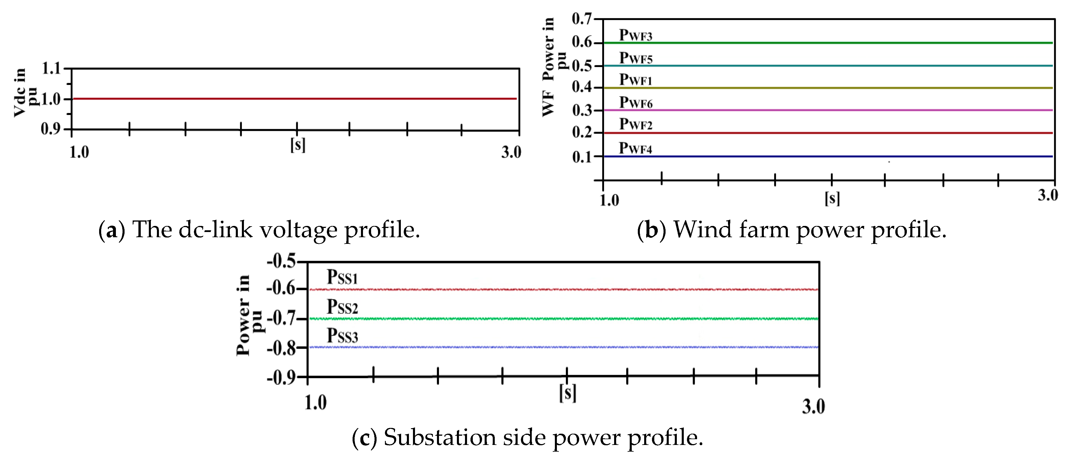
In the third case, again a permanent dc line–line fault is considered but within the SS ring as discussed in scenario-2 of Section 4.1.2. In the event of dc fault on L13, dc breakers on either side of the fault will operate and open the ring. However, the power of units-1, 2, and 3 are smoothly and continuously being exported to ac networks from the MT-HVdc grid via GS-VSC1, GS-VSC2, and GS-VSC3, since WFs are directly attached to respective substations after the operation of DCCBs. The direct voltage and power profiles are shown in Figure 15. Profiles are unaltered before and after the operation of DCCBs in the event of fault F2, which gives conformability of the proposed topology with all three standards of GBSQSS.
All the above three tests prove the superiority of the proposed 2WF-SSRT over the simulated (literature best) WFRT and 2WF-1SST. 2WF-SSRT fulfills the GBSQSS requirements and has enough protection to cope with the transients that occurred due to faults and disconnection of the GS-VSCs.
7. Annotations on Topological Evaluation of HVdc Circuits
From all of the above discussions, the following remarks are drawn on multi-terminal VSC-HVdc transmission system topologies:
- (1)
- In the context of dc breakers, ST, GRT, and SGRT require a dc breaker for each WF and onshore SS (NWF + NSS). SSRT and WFRT demand that DCCB equals the number of WFs (NWFs) while PPT does not need dc breakers (not an MT-HVdc topology). 2WF-1SST and proposed 2WF-SSRT acquire dc breakers equal to the number of substations (NSS). The fewer the requirements of dc breakers, the more economical is the topology. Thus, 2WF-1SST and 2WF-SSRT are more economical configurations than all of them.
- (2)
- No extra offshore SS is required for all discussed topologies except ST and SGRT for connections and dc breakers’ installations.
- (3)
- Pmax-fail criterion imposed by GBSQSS is satisfied during all cases but for a permanent dc fault within WF/SS ring of WFRT/SSRT, on a central star node of star topology and during onshore converter disconnection and dc-link fault within remote/far-end/the last unit (unit-1 and unit-3 of Figure 5) of 2WF-1SST is not satisfied. Stability and flexibility of the MT-HVdc grid are on the stake in the event of permanent failure of GS-VSC station in WFRT, SSRT, ST, SGRT, and GRT, unlike the proposed 2WF-SSRT. Simulations show that 2WF-SSRT is the most stable configuration as it satisfies all operating conditions of GBSQSS.
- (4)
- Proposed 2WF-SSRT cuts the complexities such as operation and control approach and the protection scheme because of the standalone operation of each unit of 2WF-SSRT without mediation and burden of the power converters, UFMA, and DCCBs from the adjoining units during the steady-state operation. However, the impact of all VSC stations, UFMAs, dc cables, and DCCBs of a configuration needs to be considered while designing/selecting control and operation, and a protection approach for all other topologies, which proves that 2WF-SSRT is a practical configuration.
8. Conclusions
In this study, available MT-HVdc transmission system topologies, as well as the one proposed by this paper, have been compared for offshore wind farms integration to onshore substations. Each topology has been characterized in terms of techno-economic factors, such as number and rating of dc circuit breakers and VSCs, the necessity of extra offshore stations, number, length and rating of dc-link, stability, flexibility, redundancy, cost, and meeting the maximum loss criterion. Simulations are developed in EMTDC/PSCAD to analyze the operation and control of the configurations in terms of (i) permanent GS-VSC disconnection and (ii) dc line–line faults. Results have shown that WFRT and 2WF-1SST are not conforming to the GBSQSS and hence not viable during GS-VSC disconnection and dc-link fault within remote/far-end/the last unit (unit-2 or unit-3 in Figure 5). Therefore, a more dynamic topology for the MT-HVdc grid is proposed and named as two wind farm and substation ring topology to overcome the aforementioned shortcomings. The proposed 2WF-SSRT is able to improve the stability, utilization, and redundancy while fulfilling the maximum loss criterion in the normal and abnormal conditions by providing an alternate path for the power flow with the least number and ratings of HVdc circuit breakers and grid side VSC-HVdc stations. Therefore, the anticipated 2WF-SSRT is a promising topology for the future wind farm MT-HVdc grids.
Author Contributions
Conceptualization, A.R.; formal analysis, A.R., M.Y., K.R., and G.A.; resources, A.R., A.A.; Investigation, A.R., M.Y., Y.L., A.A., K.R., and G.A.; software, M.Y.; Validation A.R., M.Y., A.A., K.R., and G.A.; Methodology, A.R. and M.Y.; writing—original draft preparation, A.R., M.Y., Y.L., and A.A; writing—review and editing, A.R., M.Y., Y.L., A.A., K.R., G.A., and G.A.; supervision, A.R.; project administration, A.R.; funding acquisition, A.A. All authors have read and agreed to the published version of the manuscript.
Funding
This project was funded by the Deanship of Scientific Research (DSR), King Abdulaziz University, Jeddah, under Grant No. (DF-468-611-1441). The authors, therefore, gratefully acknowledge DSR technical and financial support.
Acknowledgments
The authors are thankful to the Department of Electrical Engineering, The University of Lahore—Pakistan, and Department of Information Technology, King Abdulaziz University, Jeddah, Saudi Arabia for providing facilities to conduct this research.
Conflicts of Interest
The authors declare no conflict of interest.
Abbreviations
| 2WF-SSRT | Two wind farms and substation ring topology |
| VSC | Voltage source converter |
| ac | Alternating current |
| WF | Wind farm |
| DCCB | HVdc circuit breakers |
| PPT | Point-to-point topology |
| ST | Star topology |
| GRT | General ring topology |
| SGRT | Star with central switching topology |
| SSRT | Substation ring topology |
| WFRT | Wind farm ring topology |
| 2WF-1SST | Two wind farms one substation topology |
| PWF | Wind farm power |
| GS-VSC | Grid side VSC |
| GBSQSS | Great Britain’s security and quality of supply standards |
| Pmax-fail | Maximum power failure |
| k | Droop coefficient |
| PI | Proportional integral controller |
| P-Vac | Active power—ac voltage |
| Vdc | The dc voltage |
| Q | Reactive power |
| SS | Substation |
| UFMA | Ultra-fast mechanical actuator |
| Lij | All dc-links |
| WF-VSC | Wind farm side VSC |
| Fi | Fault |
| CB | Circuit breaker |
| t | time |
| M€ | Million Euro |
| pu | Per unit |
| TSO | transmission system operator |
| EMTDC/PSCAD | Electromagnetic transients including DC/power system computer aided design |
| NWF | Number of wind farms |
| NSS | Number of substations |
References
- Rouzbehi, K.; Miranian, A.; Luna, A.; Rodriguez, P. A generalized voltage droop strategy for control of multi-terminal DC grids. 2013 IEEE Energy Convers. Congr. Expo. 2013, 51, 59–64. [Google Scholar]
- Lamm, U.; Uhlmann, E.; Danfors, P. Some aspects of tapping HVDC transmission systems. Direct Curr. 1963, 8, 124–129. [Google Scholar]
- Reeve, J.; Arrillaga, J. Series connection of converter stations in an HVDC transmission system. Direct Curr. 1965, 10, 72–78. [Google Scholar]
- Atlantic Wind Connection. Available online: http://www.atlanticwindconnection.com (accessed on 17 September 2019).
- ABB HVDC Systems. Available online: http://www.new.abb.com/systems/hvdc (accessed on 17 September 2019).
- Raza, A.; Liu, Y.; Rouzbehi, K.; Jamil, M.; Gilani, S.O.; Dianguo, X.; Williams, B.W. Power Dispatch and Voltage Control in Multiterminal HVDC Systems: A Flexible Approach. IEEE Access 2017, 5, 24608–24616. [Google Scholar] [CrossRef] [Green Version]
- Lin, W.; Jovcic, D. Power balancing and dc fault ride through in DC grids with dc hubs and wind farms. IET Renew. Power Gener. 2015, 9, 847–856. [Google Scholar] [CrossRef] [Green Version]
- Wang, G.-D.; Wai, R.-J.; Liao, Y. Design of backstepping power control for grid-side converter of voltage source converter-based high-voltage dc wind power generation system. IET Renew. Power Gener. 2013, 7, 118–133. [Google Scholar] [CrossRef]
- Raza, A.; Mustafa, A.; Rouzbehi, K.; Jamil, M.; Gilani, S.O.; Abbas, G.; Farooq, U.; Shehzad, M.N.; Farooq, U. Optimal Power Flow and Unified Control Strategy for Multi-Terminal HVDC Systems. IEEE Access 2019, 7, 92642–92650. [Google Scholar] [CrossRef]
- Eghtedarpour, N.; Farjah, E. Distributed charge/discharge control of energy storages in a renewable-energy-based DC micro-grid. IET Renew. Power Gener. 2014, 8, 45–57. [Google Scholar] [CrossRef]
- Kumar, M.; Singh, S.N.; Srivastava, S.C.; Ramamoorty, M. Development of a control strategy for interconnection of islanded direct current microgrids. IET Renew. Power Gener. 2015, 9, 284–296. [Google Scholar] [CrossRef]
- Van Hertem, D.; Ghandhari, M. Multi-terminal VSC HVDC for the European supergrid: Obstacles. Renew. Sustain. Energy Rev. 2010, 14, 3156–3163. [Google Scholar] [CrossRef]
- Xu, L.; Williams, B.W.; Yao, L. Multi-terminal DC transmission systems for connecting large offshore wind farms. In Proceedings of the IEEE Pes General Meeting, Pittsburgh, PA, USA, 20–24 July 2008; pp. 1–7. [Google Scholar] [CrossRef]
- Dierckxsens, C.; Srivastava, K.; Reza, M.; Cole, S.; Beerten, J.; Belmans, R. A distributed DC voltage control method for VSC MTDC systems. Electr. Power Syst. Res. 2012, 82, 54–58. [Google Scholar] [CrossRef] [Green Version]
- Da Silva, R.; Teodorescu, R.; Rodriguez, P. Multilink DC transmission system for supergrid future concepts and wind power integration. In Proceedings of the IET Conference on Renewable Power Generation (RPG 2011), Edinburgh, UK, 6–8 September 2011; p. 112. [Google Scholar]
- Vrana, T.K.; Torres-Olguin, R.E.; Liu, B.; Haileselassie, T.M. The North Sea super grid—A technical perspective. In Proceedings of the 9th IET International Conference on AC and DC Power Transmission (ACDC 2010), London, UK, 19–21 October 2010; pp. 1–5. [Google Scholar]
- Naeem, R.; Khan, M.A.S.; Ali, Z.; Sultan, W.; Naeem, F. Impact of DC grid topology on transient stability of HVDC-segmented power system. In Proceedings of the 2016 International Conference on Intelligent Systems Engineering (ICISE), Islamabad, Pakistan, 15–17 January 2016; pp. 51–54. [Google Scholar]
- Naeem, R.; Cheema, M.S.; Ahmad, M.; Haider, S.A.; Shami, U.T. Impact of HVDC grid segmentation topology on transient stability of HVDC-segmented electric grid. In Proceedings of the 2015 International Conference on Open Source Systems & Technologies (ICOSST), Lahore, Pakistan, 17–19 December 2015; pp. 132–136. [Google Scholar]
- Norrga, S.; Li, X.; Angquist, L. Converter topologies for HVDC grids. In Proceedings of the 2014 IEEE International Energy Conference (ENERGYCON), Cavtat, Croatia, 13–16 May 2014; pp. 1554–1561. [Google Scholar]
- Schon, A.; Bakran, M.-M. High power HVDC-DC converters for the interconnection of HVDC lines with different line topologies. In Proceedings of the 2014 International Power Electronics Conference (IPEC-Hiroshima 2014—ECCE ASIA), Hiroshima, Japan, 18–21 May 2014; pp. 3255–3262. [Google Scholar]
- Didem, A. Examination of Different Communication Topologies for Distributed Control of Multi-terminal HVDC Grids. Int. J. Comput. Sci. Netw. Secur. 2019, 19, 1–8. [Google Scholar]
- Haileselassie, T.M.; Uhlen, K. Impact of DC Line Voltage Drops on Power Flow of MTDC Using Droop Control. IEEE Trans. Power Syst. 2012, 27, 1441–1449. [Google Scholar] [CrossRef]
- Zhou, K.; Fu, X.; Cheng, M.; Zhu, X.; Wang, W.; Wang, T. Topologies and control of VSC-HVDC systems for grid connection of large-scale off-shore wind farms. In Proceedings of the 2008 International Conference on Electrical Machines and Systems, Wuhan, China, 17–20 October 2008; pp. 2357–2361. [Google Scholar]
- Prieto-Araujo, E.; Egea-Alvarez, A.; Fekriasl, S.; Gomis-Bellmunt, O. DC voltage droop control design for multi-terminal HVDC systems considering AC and DC grid dynamics. In Proceedings of the 2016 IEEE Power and Energy Society General Meeting (PESGM), Boston, MA, USA, 17–21 July 2016. [Google Scholar]
- Kontos, E.; Pinto, R.T.; Rodrigues, S.; Bauer, P. Impact of HVDC transmission system topology on multiterminal DC network faults. IEEE Trans. Power Deliv. 2015, 30, 844–852. [Google Scholar] [CrossRef]
- Ademi, S.; McMahon, R.; Zhu, L.; Sadeghi, R. Impact of transmission topology for protective operations in multi-terminal HVDC networks. In Proceedings of the 2019 IEEE International Conference on Industrial Technology (ICIT), Melbourne, Australia, 13–15 February 2019; pp. 1784–1789. [Google Scholar]
- Hertem, D.V.; Gomis-Bellmunt, O.; Liang, J. HVDC Grids: For Offshore and Supergrid of the Future; John Wiley & Sons: Hoboken, NJ, USA, 2016. [Google Scholar]
- Gomis-Bellmunt, O.; Liang, J.; Ekanayake, J.; King, R.; Jenkins, N. Topologies of multiterminal HVDC-VSC transmission for large offshore wind farms. Electr. Power Syst. Res. 2011, 81, 271–281. [Google Scholar] [CrossRef]
- Raza, A.A.; Diangou, B.X.; Xunwen, C.S.; Weixing, D.L. Appraisal of VSC based MTDC system topologies for offshore wind farms. In Proceedings of the 2015 9th International Conference on Power Electronics and ECCE Asia (ICPE-ECCE Asia), Seoul, Korea, 1–5 June 2015; pp. 2141–2147. [Google Scholar]
- Raza, A.; Dianguo, X.; Xunwen, S.; Weixing, L.; Williams, B.W. A Novel Multi-terminal VSC-HVDC Transmission Topology for Offshore Wind Farms. IEEE Trans. Ind. Appl. 2016, 53, 1316–1325. [Google Scholar] [CrossRef]
- OTEG Offshore Transmission Expert Group—GBSQSS Great Britain Security and Quality of Supply Sub-Group, Recommendations for the Coverage of Offshore Transmission Networks in the Great Britain Security and Quality of Supply Standard. Available online: https://www.ofgem.gov.uk/electricity/transmission-networks/offshore-transmission/forums-seminars-and-working-groups/great-britain-security-and-quality-supply-standard-working-group (accessed on 17 September 2019).
- National Grid Electricity Transmission (NGET), Offshore Electricity Transmission Access and Compensation, in Industry Workshop on 3 December 2007. Available online: https://www.ofgem.gov.uk/ofgem-publications/51174/nget-gbso-full-response (accessed on 17 September 2019).
- Raza, A.; Dianguo, X.; Yuchao, L.; Xunwen, S.; Williams, B.W.; Cecati, C. Coordinated Operation and Control of VSC Based Multiterminal High Voltage DC Transmission Systems. IEEE Trans. Sustain. Energy 2015, 7, 364–373. [Google Scholar] [CrossRef] [Green Version]
- Shaheen, S.; Raza, A.; Khalid, R.; Javed, A. An Adaptive Voltage Droop Control mechanism for Multi-Terminal VSC-HVDC System for Offshore Wind Farms. In Proceedings of the International Conference on Power Generation Systems and Renewable Energy Technologies (PGSRET), Islamabad, Pakistan, 10–12 September 2018; pp. 1–5. [Google Scholar]
- Raza, A.; Shakeel, A.; Altalbe, A.A.; Alassafi, M.O.; Yasin, A.R. Impacts of MT-HVDC Systems on Enhancing the Power Transmission Capability. Appl. Sci. 2019, 10, 242. [Google Scholar] [CrossRef]
- Westermann, D.; Van Hertem, D.; Real, G.; Rauhala, T.; Meisingset, M.; Kurrat, M.; Deppe, B.; Atmuri, R.; Küster, A.; Soerangr, D.; et al. Voltage Source Converter (VSC) HVDC for Power Transmission—Economic Aspects and Comparison with other AC and DC Technologies. In CIGRE Technical Brochure 492 by Working Group B4–46, 2012; CIGRE: Paris, France, 2012. [Google Scholar]
- Gunnar, A.; Kerstin, L.; Carl, B.; Andree, M.; Ulf, B.; Nalin, P.; Jef, B.; Mohamed, R.; Peter, C.; Jürgen, R.; et al. HVDC Grid Feasibility Study. In CIGRE Technical Brochure by Working Group B4–52; CIGRE: Paris, France, 2013. [Google Scholar]
- Available online: http://carboncopycommunications.com/business-trade-press/enabling-offshore-wind-and-connecting-countries/ (accessed on 20 March 2019).
- Liang, J.; Jing, T.; Gomis-Bellmunt, O.; Ekanayake, J.; Jenkins, N. Operation and Control of Multiterminal HVDC Transmission for Offshore Wind Farms. IEEE Trans. Power Deliv. 2011, 26, 2596–2604. [Google Scholar] [CrossRef]
- Ased, G.P.; Li, R.; Holliday, D.; Finney, S.; Xu, L.; Williams, B.W.; Kuroda, K.; Yamamoto, R.; Ito, H. Continued Operation of Multi-Terminal HVDC Networks Based on Modular Multilevel Converters. In Proceedings of the Cigré International Symposium, Lund, Sweden, 27–28 May 2015; pp. 1–8. [Google Scholar]
- Raza, A.; Akhtar, A.; Jamil, M.; Abbas, G.; Gilani, S.O.; Liu, Y.; Khan, M.; Izhar, T.; Dianguo, X.; Williams, B.W.; et al. A Protection Scheme for Multi-Terminal VSC-HVDC Transmission Systems. IEEE Access 2018, 6, 3159–3166. [Google Scholar] [CrossRef]
- Tahata, K.; Ito, H.; Yamamoto, R.; Kamei, K.; Kono, Y.; El Oukaili, S.; Yoshida, D. HVDC circuit breakers for HVDC grid applications. In Proceedings of the 11th IET International Conference on AC and DC Power Transmission, Brimingham, UK, 10–12 Feburary 2015; pp. 1–9. [Google Scholar]
- Eriksson, T.H.; Backman, M.; Halen, S. A low loss mechanical HVDC breaker for HVDC Grid applications. In Proceedings of the CIGRE Session, Paris, France, 24–29 August 2014; pp. 1–7. [Google Scholar]
Figure 1.
The dc voltage droop control using the d-q reference frame.
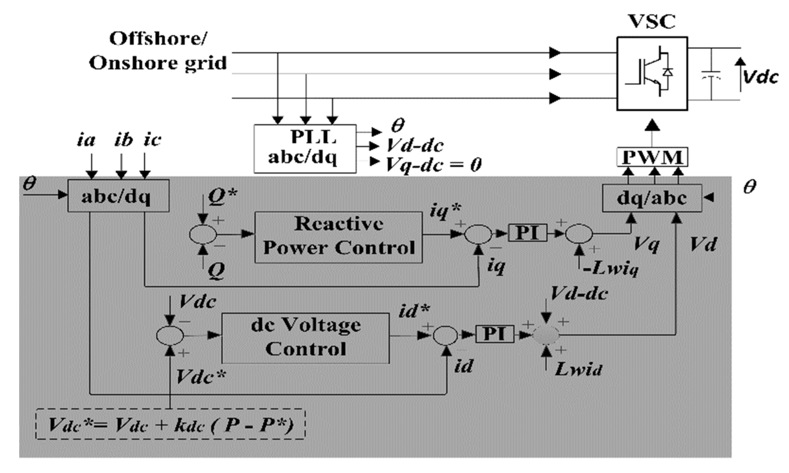
Figure 2.
Direct voltage droop controller.

Figure 3.
WFRT topology.
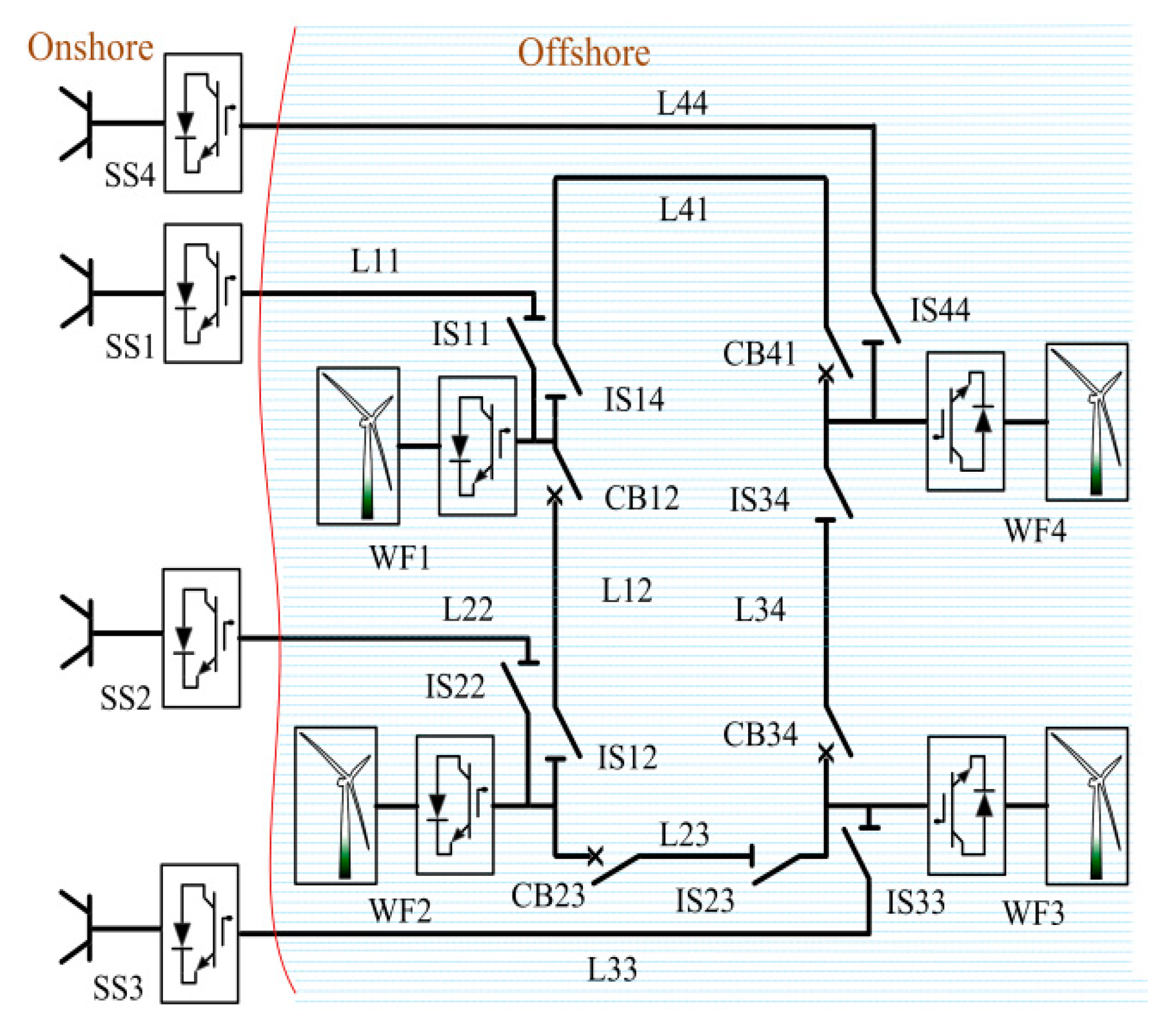
Figure 4.
SSRT topology.
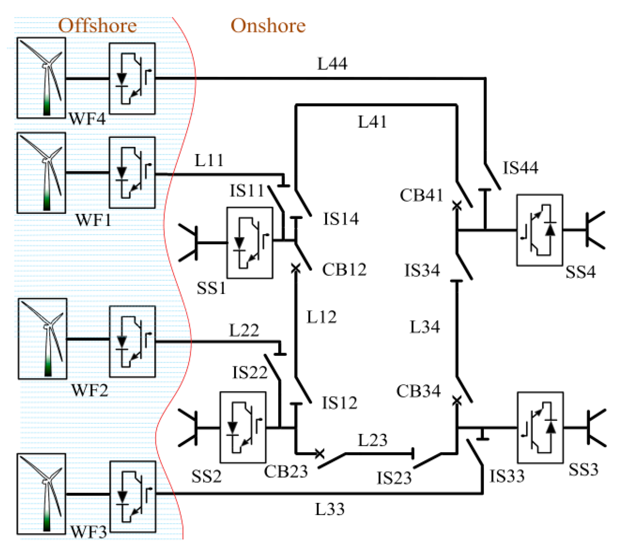
Figure 5.
2WF-1SST topology.

Figure 6.
2WF-SSRT topology.
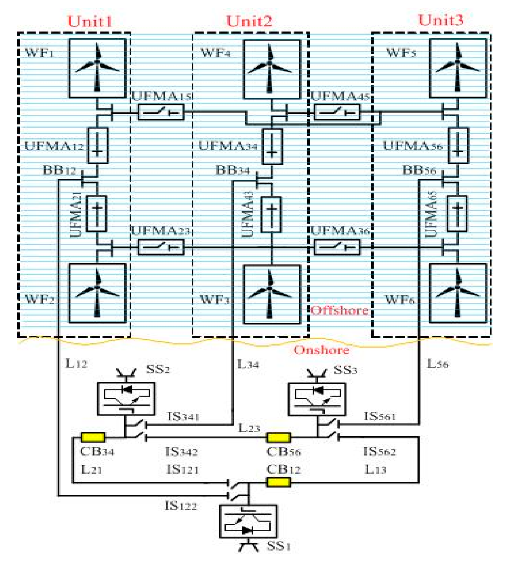
Figure 7.
2WF-SSRT topology operation in the event of a fault on the line L12: (a) at t0, 2WF-1SST topology during normal operation, (b) at t1, fault appears on the line L12, (c) at t2, CB12 and CB34 operates, (d) at t3, IS122, UFMA12, and UFMA21 open (e) at t4, first UFMA15 and UFMA23 are closed and then CB12 and CB34 re-closed as well.
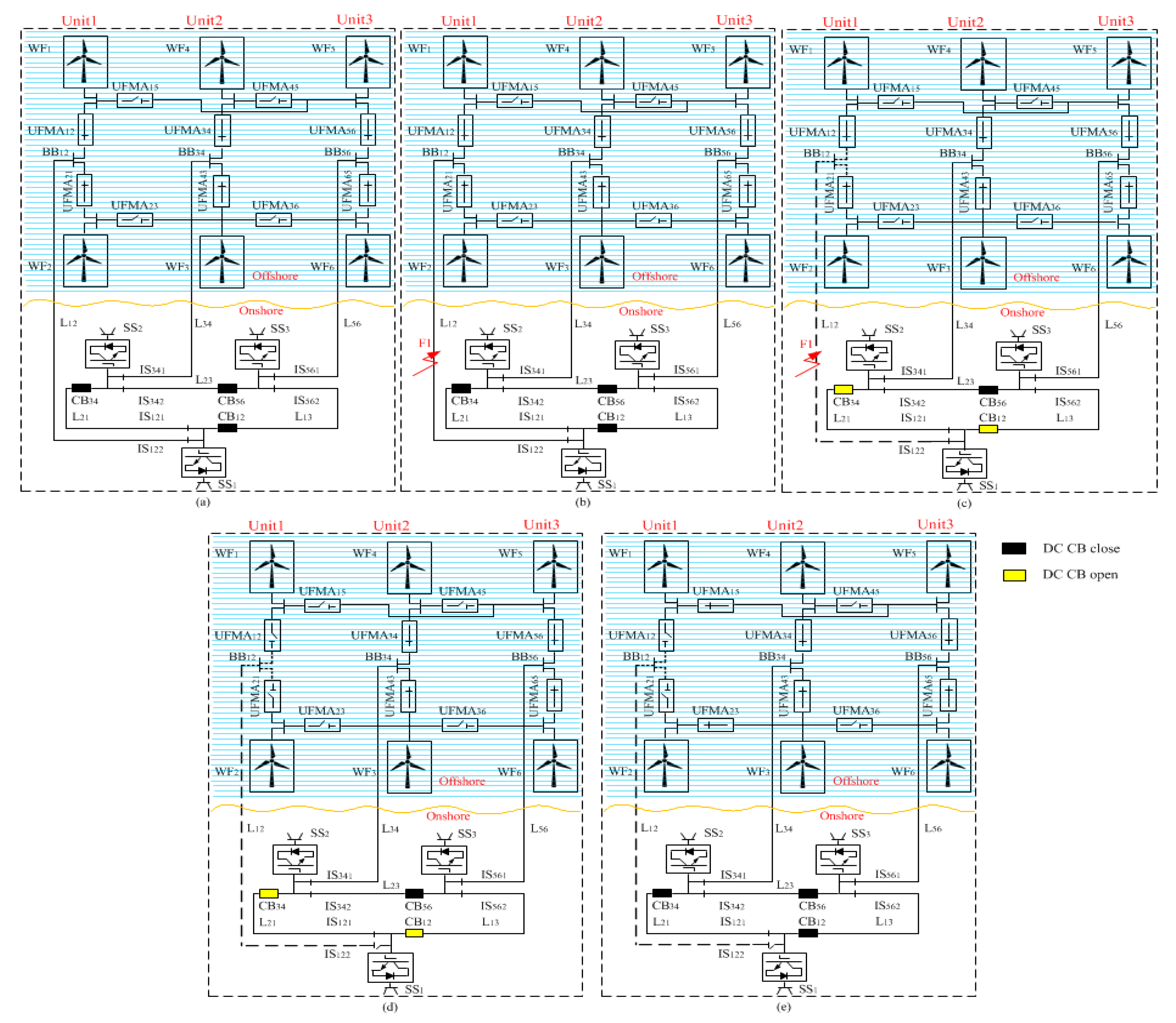
Figure 8.
General case study established for various topologies (a) GRT, (b) ST, (c) WFRT, (d) SSRT, and (e) 2WF-1SST, (f) 2WF-SSRT.
Figure 8.
General case study established for various topologies (a) GRT, (b) ST, (c) WFRT, (d) SSRT, and (e) 2WF-1SST, (f) 2WF-SSRT.
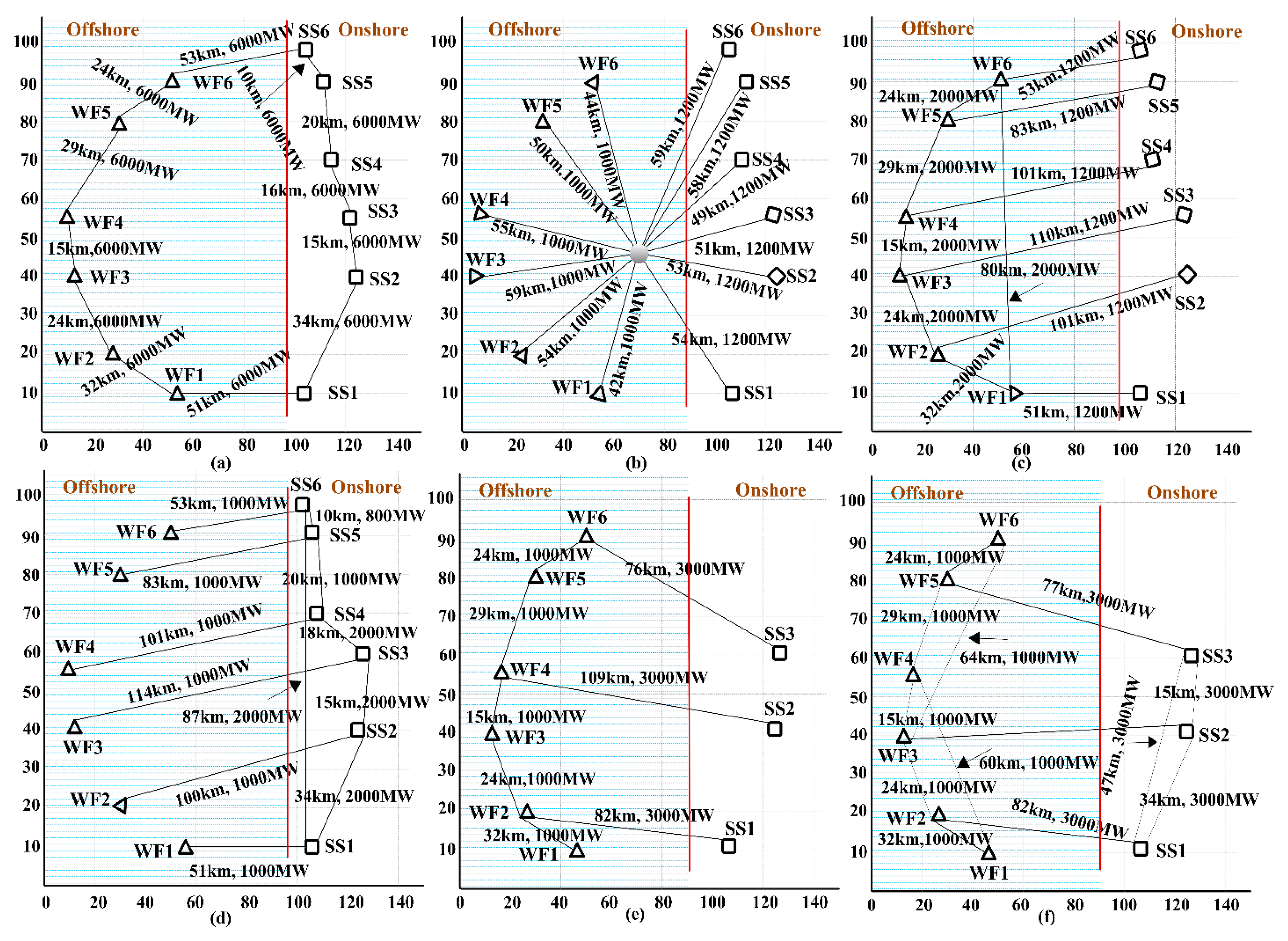
Figure 9.
Disconnection of GS-VSC1 from WFRT.
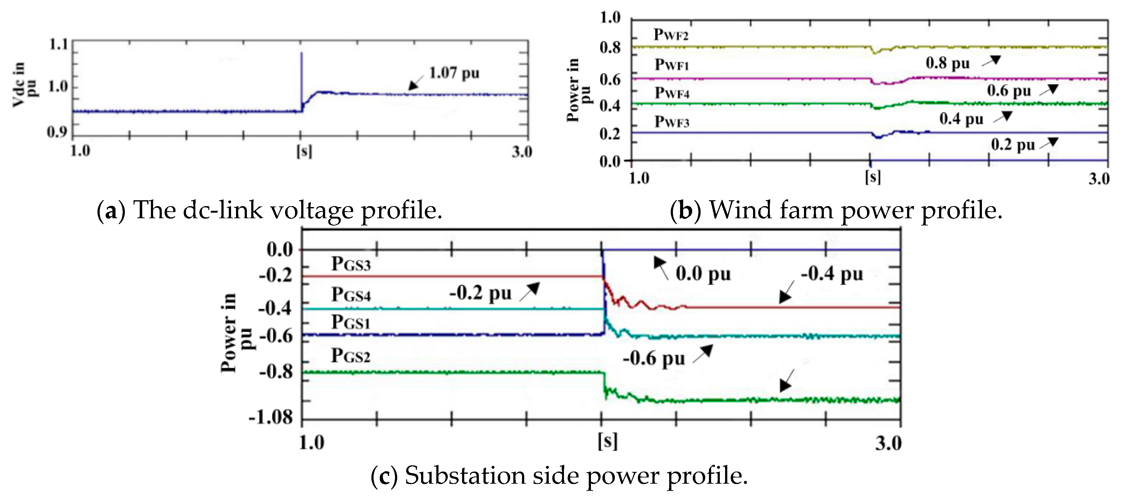
Figure 10.
A dc fault on the line L41 of the WF ring.

Figure 11.
Disconnection of GS-VSC1 from the 2WF-1SST.
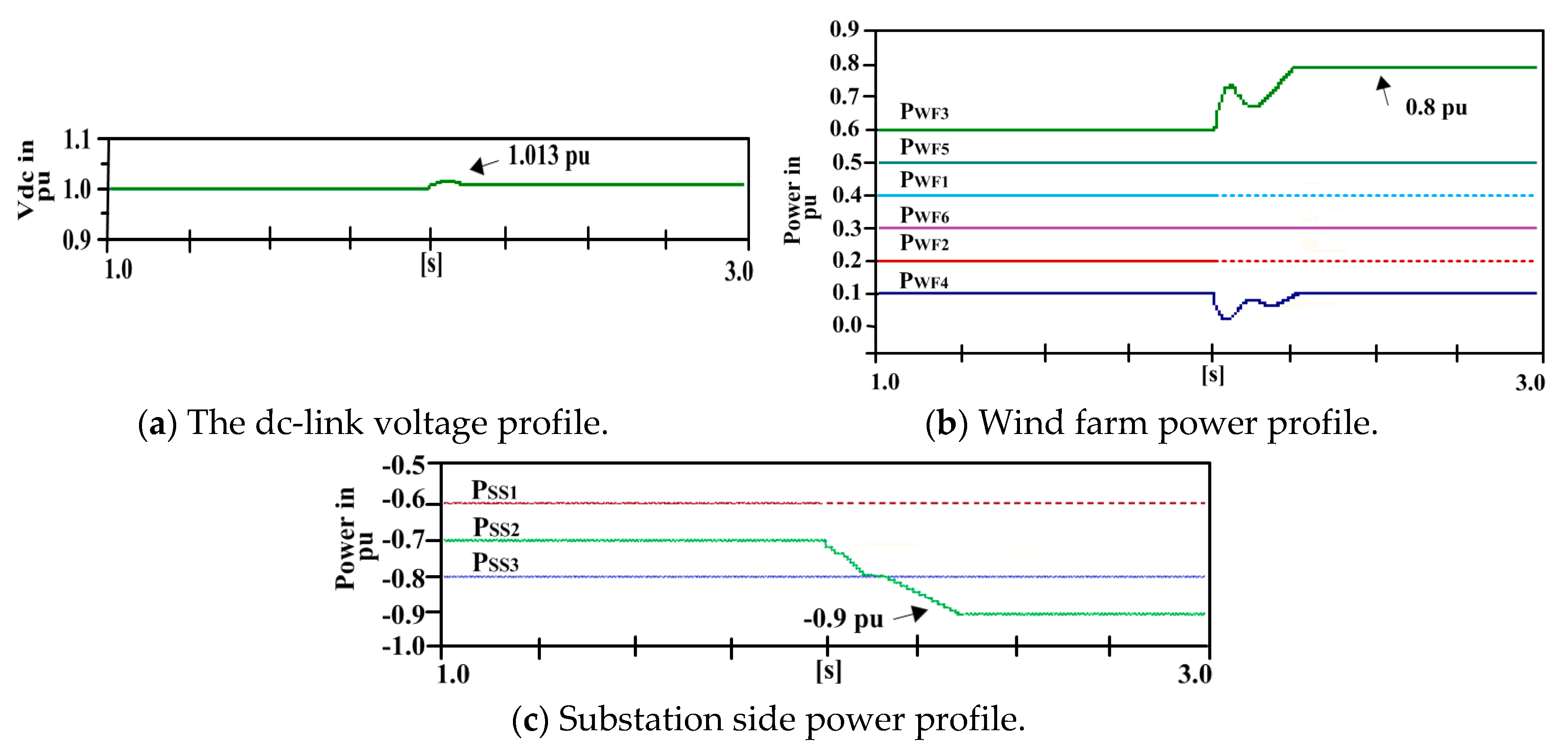
Figure 12.
Line–line dc fault on cable L56.
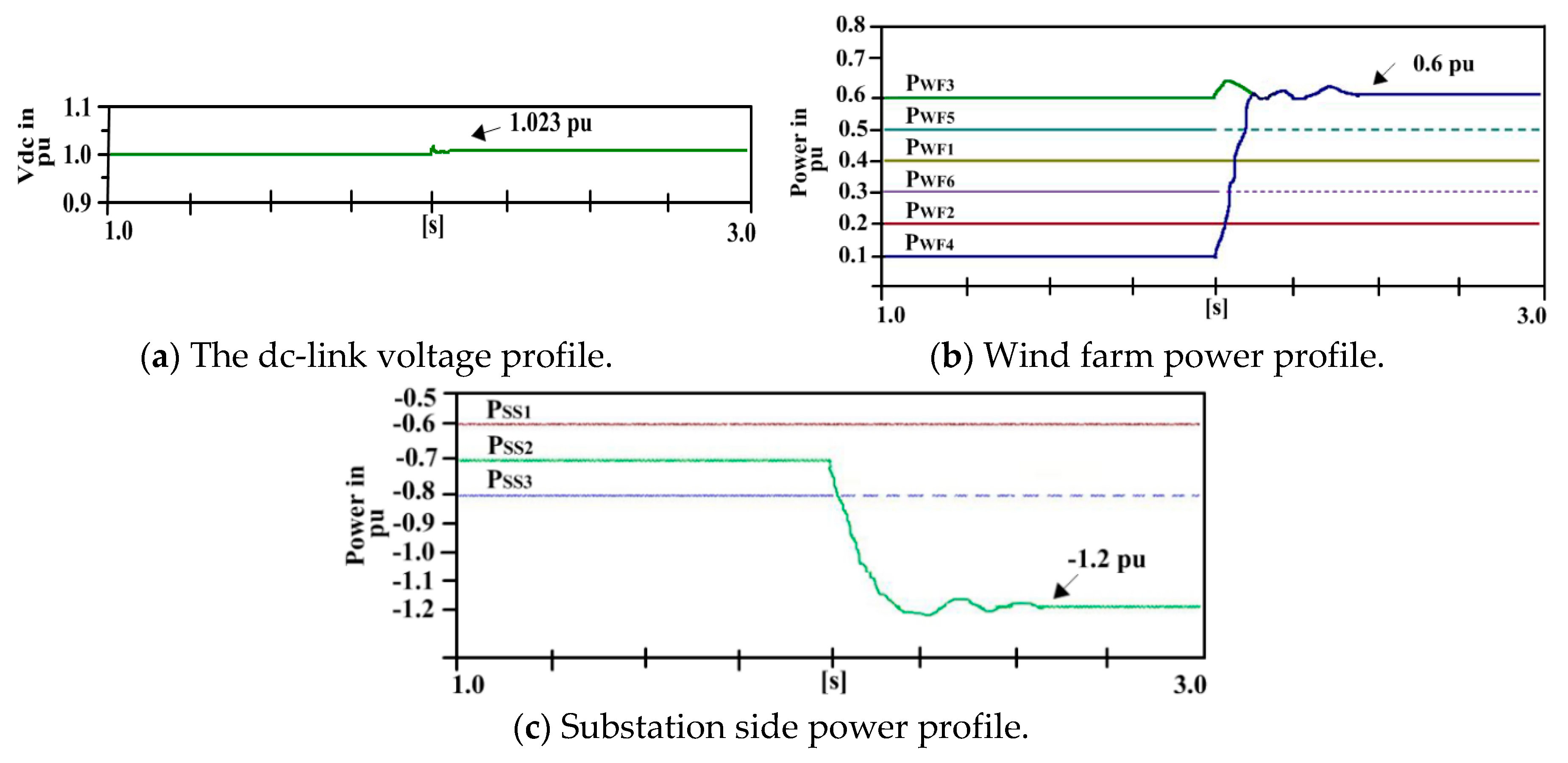
Figure 13.
Disconnection of GS-VSC1 within the SS ring of the 2WF-SSRT.
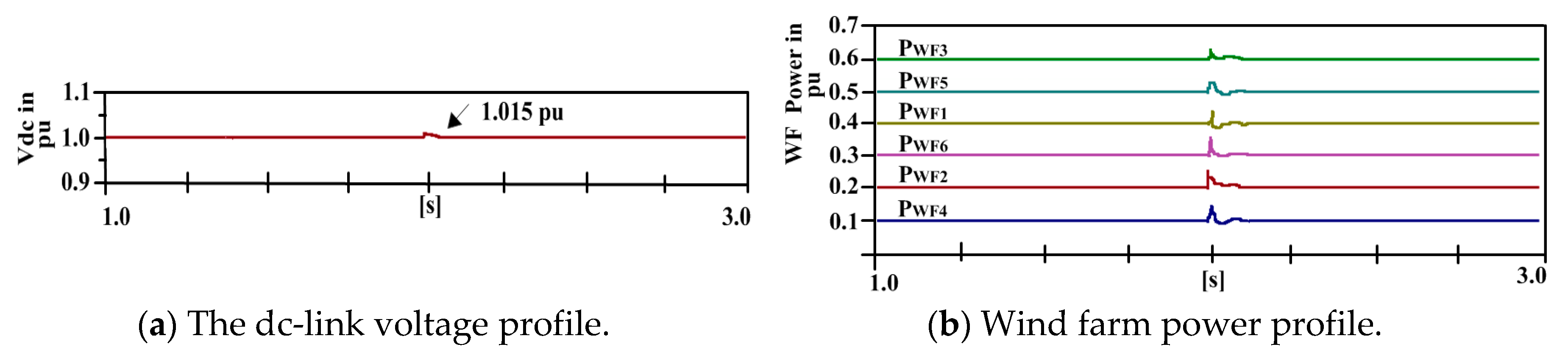
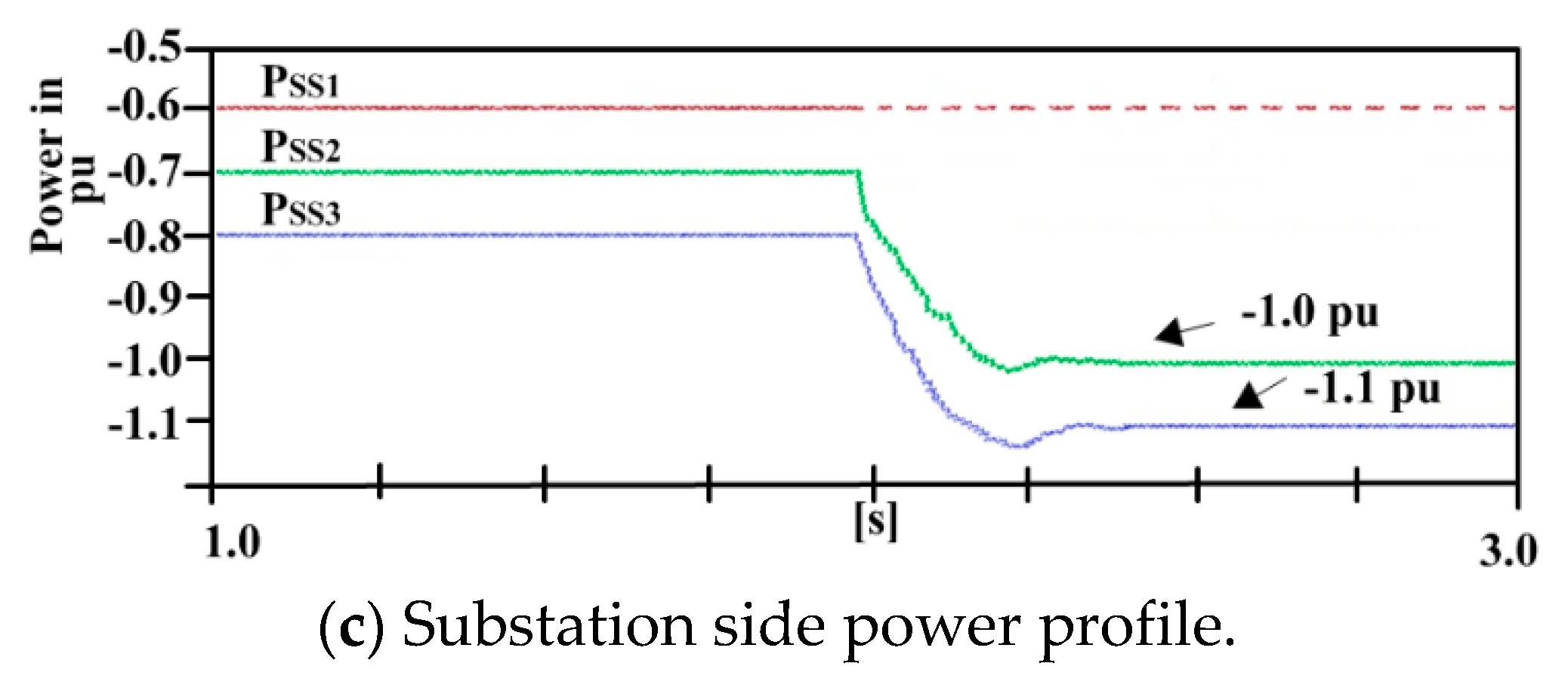
Figure 14.
Permanent dc line–line fault F1 on cable L12.
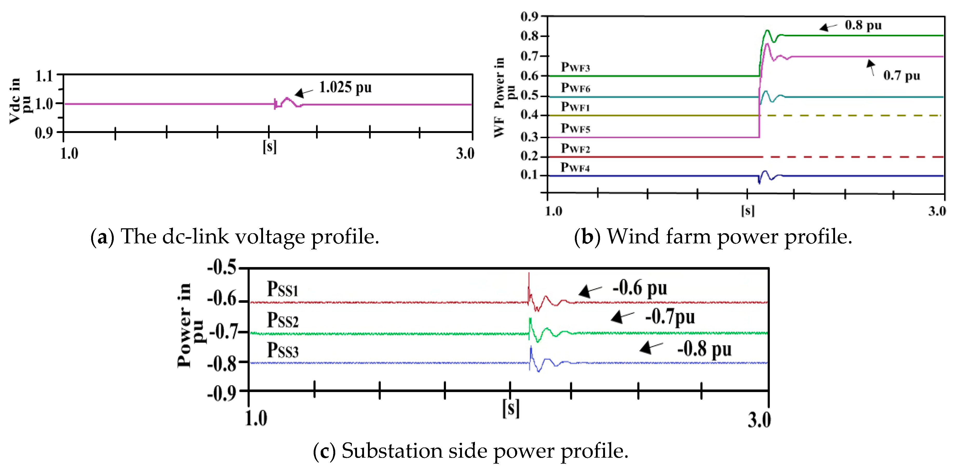
Figure 15.
Permanent dc line–line fault F2 on cable L13 within substation ring.

Table 1.
Control parameters and systems specifications.
| DC Grid Specifications | ||
|---|---|---|
| Parameters | Values | |
| DC grid voltage | 400 kV | |
| Droop coefficients k1, k2, k3, k4, k5, k6 | 5, 7, 4, 5, 3, 6 | |
| Max. power of each VSC | 1000 MW | |
| Converter capacitance | 1400 µF | |
| Coupling inductance | 2.5 mH | |
| DC lines | Inductance | Resistance |
| All DC links (Lij) | 0.50 mH | 0.10 Ω |
| PI Control Parameters | ||
| PI controller | Ti | Kp |
| q-axis PI | 0.0067 | 0.48 |
| d-axis PI | 0.0067 | 0.48 |
| P controller | 0.0400 | 0.01 |
| WF ac voltage PI | 1.0000 | 1.00 |
Table 2.
Geographical positions of WF-VSCs and GS-VSCs for topologies.
| Wind Farm | Horizontal (km) | Vertical (km) | Sub Station | Horizontal (km) | Vertical (km) |
|---|---|---|---|---|---|
| WF1 | 50 | 10 | SS1 | 101 | 10 |
| WF2 | 20 | 20 | SS2 | 128 | 45 |
| WF3 | 10 | 35 | SS3 | 125 | 70 |
| WF4 | 11 | 60 | SS4 | 123 | 80 |
| WF5 | 30 | 82 | SS5 | 110 | 91 |
| WF6 | 50 | 92 | SS6 | 102 | 95 |
| Centre point for ST | 75 | 45 | |||
Table 3.
Summary of the general case study.
| Topology | No. of CBs | Rating of CBs (MW) | No. of Cables | Total Length of Cables (km) | Rating of Cables (MW) | No. of VSCs | Rating of VSCs (MW) | Utilization | |||||||
|---|---|---|---|---|---|---|---|---|---|---|---|---|---|---|---|
| WF | GS | WF | GS | WF | GS | WF | GS | WF | GS | WF | GS | ||||
| PPT | - | - | 6 | 531 | 400 | 6 | 6 | 400 | 400 | 100% | |||||
| GRT | 7 | 5 | 2400 | 2400 | 7 | 5 | 332 | 2400 | 2400 | 6 | 6 | 2400 | 2400 | 20–50% | |
| ST | 6 | 6 | 400 | 480 | 6 | 6 | 671 | 400 | 480 | 6 | 6 | 400 | 480 | 80–100% | |
| WFRT | Ring | 6 | - | 800 | - | 6 | - | 208 | 800 | - | 6 | - | 800 | - | 50% |
| Line | - | - | - | - | - | 6 | 519 | - | 480 | - | 6 | - | 480 | 80% | |
| Total | 12 | 727 | 12 | - | |||||||||||
| SSRT | Ring | - | 6 | - | 800 | - | 6 | 190 | - | 800 | - | 6 | - | 800 | 50% |
| Line | - | - | - | - | 6 | - | 519 | 400 | - | 6 | - | 400 | - | 80% | |
| Total | 12 | 709 | 12 | - | |||||||||||
| 2WF-1SST | - | 3 | - | 1200 | 5 | 3 | 403 | 800−400 | 1200 | 6 | 3 | 400 | 1200 | 67–100% | |
| 2WF-SSRT | - | 3 | - | 800 | 5 | 3 | 800−400 | 800 | 6 | 3 | 400 | 800 | 80–100% | ||
Table 4.
Comparison of MT-HVdc system topologies.
| Topology | No. of DCCB | No. of HVdc Link | Extra Offshore Substation | Flexibility | Stability | Redundancy | Comm | Remarks | |
|---|---|---|---|---|---|---|---|---|---|
| PPT | Zero | NWF = NSS | No | No | Yes | No | No | Single terminal, not flexible | |
| GRT | NWF + NSS | NWF + NSS | No | Excellent | Moderate | Excellent | Yes | Flexible but the dc-link have to be rated at full system’s power | |
| ST | WF side | NWF + NSS | NWF | Yes | Bad | Excellent | Moderate | No | The rating of dc circuits of GS-VSC and WF-VSC are equal. Fault in the central star node will collapse the system |
| SS side | Zero | NSS | No | Excellent | Bad | Moderate | No | ||
| Total | NWF + NSS | NWF + NSS | Yes | Moderate | Moderate | Moderate | No | ||
| SGRT | WF side | NWF + NSS | NWF | Yes | Bad | Excellent | Moderate | No | Full power rating dc-link required in the central ring. Moderately flexible and stable |
| SS side | Zero | NSS | No | Excellent | Bad | Moderate | No | ||
| Total | NWF + NSS | NWF + NSS | Yes | Moderate | Moderate | Moderate | No | ||
| WFRT | WF side | NWF | NWF | No | Excellent | Excellent | Excellent | Yes | Requires a number of DCCBs equal to WFs. Flexible on the WFs side. Poor stability during fault inside the GS-VSC. |
| SS side | Zero | NSS | No | Bad | Bad | Moderate | Yes | ||
| Total | NWF | NWF + NSS | No | Moderate | Moderate | Moderate | Yes | ||
| SSRT | WF side | Zero | NWF | No | Bad | Bad | Moderate | Yes | Good stability but poor redundancy and flexibility. Number of HVdc CB is equal to NSS |
| SS side | NSS | NSS | No | Excellent | Excellent | Excellent | Yes | ||
| Total | NSS | NWF + NSS | No | Moderate | Moderate | Moderate | Yes | ||
| 2WF-1SS | WF side | Zero | NWF | No | Moderate | Moderate | Moderate | Yes | The number of DCCB is half to WFs. Moderate flexibility and stability |
| SS side | NSS | NSS | No | Bad | Bad | Bad | Yes | ||
| Total | NSS | NWF + NSS | No | Moderate | Moderate | Moderate | Yes | ||
| WF-SSRT | WF side | Zero | NWF | No | Excellent | Excellent | Excellent | Yes | Excellent flexibility, stability, and redundancy with the same number of HVdc CB as in 2WF-1SS |
| SS side | NSS | NSS | No | Excellent | Excellent | Excellent | Yes | ||
| Total | NSS | NWF + NSS | No | Excellent | Excellent | Excellent | Yes |
© 2020 by the authors. Licensee MDPI, Basel, Switzerland. This article is an open access article distributed under the terms and conditions of the Creative Commons Attribution (CC BY) license (http://creativecommons.org/licenses/by/4.0/).
Share and Cite
MDPI and ACS Style
Raza, A.; Younis, M.; Liu, Y.; Altalbe, A.; Rouzbehi, K.; Abbas, G. A Multi-Terminal HVdc Grid Topology Proposal for Offshore Wind Farms. Appl. Sci. 2020, 10, 1833. https://doi.org/10.3390/app10051833
AMA Style
Raza A, Younis M, Liu Y, Altalbe A, Rouzbehi K, Abbas G. A Multi-Terminal HVdc Grid Topology Proposal for Offshore Wind Farms. Applied Sciences. 2020; 10(5):1833. https://doi.org/10.3390/app10051833
Chicago/Turabian StyleRaza, Ali, Muhammad Younis, Yuchao Liu, Ali Altalbe, Kumars Rouzbehi, and Ghulam Abbas. 2020. "A Multi-Terminal HVdc Grid Topology Proposal for Offshore Wind Farms" Applied Sciences 10, no. 5: 1833. https://doi.org/10.3390/app10051833
Note that from the first issue of 2016, this journal uses article numbers instead of page numbers. See further details here.