Featured Application
One of the progressive machining methods for machining of exotic alloys is trochoidal milling. The main contribution of this paper is the analysis of basic parameters of trochoidal movement for the prediction of their impacts on the machining force. Knowledge of these predictions will make it possible to decide more effectively, on the selection of trochoidal parameters. Results from not only this paper, but our whole research on trochoidal milling are applied in various companies located near the city of the University of Zilina, such as IGV Technologies and LAGO instruments, but also local factories of well-known companies Volkswagen Slovakia, Schaeffler Kysuce, etc.
Abstract
Current demands on quality are the engine of searching for new progressive materials which should ensure enough durability in real conditions. Due to their mechanical properties, however, they cannot be applied to conventional machining methods. In respect to productivity, one of the methods is the finding of such machining technologies which allow achieving an acceptable lifetime of cutting tools with an acceptable quality of a machined surface. One of the mentioned technologies is trochoidal milling. Based on our previous research, where the effect of changing cutting conditions (cutting speed, feed per tooth, depth of cut) on tool lifetime was analysed, next, we continued with research on the influences of trochoid parameters on total machining force (step and engagement angle) as parameters adjustable in the CAM (computer-aided machining) system. The main contribution of this research was to create a mathematical-statistical model for the prediction of cutting force. This model allows setting up the trochoid parameters to optimize force load and potentially extend the lifetime of the cutting tool.
1. Introduction
1.1. Productive Technologies of Machining
Research of the productivity issue is relevant mainly in such industry areas where it is necessary to solve the removal of a large volume of material in a short time. In connection with the continuous application of materials known to be hard-to-machine, a variety of methods known as productive technologies have been developed. In this area, research focuses mainly on cutting parameter adjustment or tool path optimization [1,2,3]. It also studies chip formation [4] and selected parameters of surface integrity [1,5]. Significant studies have also been carried out in this field, focusing on tool wear, machining not only steel materials but also nickel and titanium alloys [6,7,8].
One of the methods of productive technologies is trochoidal milling, which is increasingly finding its use for machining of materials with difficult machinability. Correct implementation of the technology also allows meeting the ever-increasing requirements for product quality with adequate productivity [5,9].
1.2. Trochoidal Milling
1.2.1. Research of Trochoidal Milling
Trochoidal milling is an effective method not only for milling complex workpieces but also for milling relatively simple grooves. Compared to standard linear grooving, trochoidal grooving allows a single milling cutting tool to machine a groove of the desired width, at least a greater width than the diameter of the milling cutting tool, the production of the groove being limited only by the wear of the milling cutting tool. Multi-blade cutting tools can also be used to allow large table shift. In addition, very high cutting speeds and feeds can be applied at a relatively small radial depth of the cut [9,10].
Currently, trochoidal milling offers the most extensive opportunities with which it is possible to remove a greater volume of material in less time (compared to conventional milling). This technology can be applied for the production of deep grooves, pockets or high workpiece sides, with high process reliability and long tool life, although the workpiece material is usually hard to machine [10,11,12]. The evolution of knowledge and skills related to the possibilities of modern machining has taken about half a century, but the development of machining has gradually accelerated. Basic knowledge in the field of trochoidal machining in professional practice can be dated to this millennium. Materials harder to process are widely used in the aircraft, automotive, shipbuilding and energy industries for the production of complex and varied components; therefore, materials based on nickel, titanium and steels with improved mechanical properties have been investigated in order to understand the factors degrading the machining process thoroughly. In recent decades, various milling methods have been investigated and analysed to increase productivity [1,13,14,15], the subject of the investigation also included the following aspects: high-speed machining with respect to the removed material [2,13,14]; simulation methods aiming to implement different control models and the real behaviour of machines to eliminate machine failure and downtime [16,17]; adjusting tool feeds aiming to optimize the production cycle time; process monitoring to evaluate tool wear for titanium or nickel-based alloys [1,18]. The possibilities of the predictive model are control of the machining process in order to reduce vibrations, increase the stability of the cut and efficiency of the cutting process [19]; and trochoidal milling in connection with finish operations in machining superalloys based on nickel [20,21,22].
1.2.2. Analysis of Trochoidal Milling
The term trochoidal milling is based on the mathematical definition which defines the trochoidal path as a curve created by point fixed to a circle rolling along a line. In the machining application, trochoidal milling is referred to as machining where the tool does not move linearly, and the cutting angle is constant. Our research is focused on the first case where the trochoid axis is primarily linear, as discussed below. A jump in technological development allowed for the precise setting of the minimum angle of cut of the cutting tool, which significantly reduces tool vibration. Reduction of the engagement angle is particularly advantageous in the side milling of grooves and pockets where the position of the milling cutting tool relative to the workpiece is easily changeable, and also when machining very hard materials, where relatively large frictional forces are produced, resulting in considerable warming. The centre of the tool moves directionally in the desired direction, with the milling machine rotating; a combination of both types of motion forms a curve, a cyclic spiral with a conventionally fixed name—trochoid (Figure 1) [11].
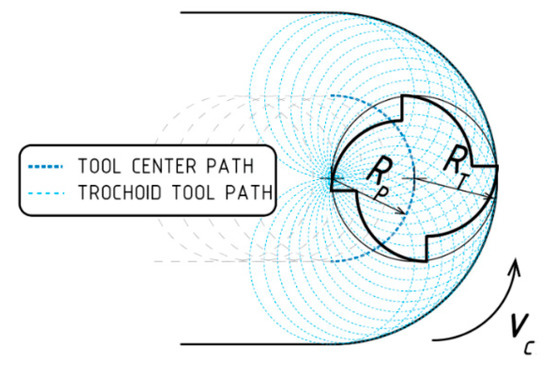
Figure 1.
Geometric representation of the tool path [11], where: RT is the radius of the milling cutting tool; RP is the radius of the milling cutting circle.
The milling cutting tool takes the material off in relatively thin layers, but at a relatively fast feed rate; therefore, it is relatively less loaded with considerable performance. The effect of small radial cutting forces increases the stability of the cut, i.e., there is a substantial decrease in pushing the tool away from to the workpiece as a response, and in the vibration. While increasing the cutting speed and reducing chip thickness, the heat generated at the cutting point is reduced, so it is possible to increase the cutting depth as needed. These positively changed milling conditions ensure that the tool and the machine are more wear-resistant, exhibiting a much longer service life, and the machining process thus becomes very effective and desirable in many new applications [5,19].
The essential knowledge, especially on theoretical issues of trochoidal machining, was already applied in the last century. The technical term “trochoidal milling” is now commonly used conventionally, despite certain deviations of the real movement of the milling cutting tool compared to mathematically predicted trochoidal trajectories [23] manifesting themselves mainly as smaller spaces at the beginning of the cut and more significant gaps at the end of the cut (Figure 2).
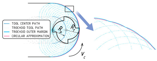
Figure 2.
Geometric representation of the trochoid and circular tool paths, where: RT is the radius of the milling cutting tool; RP is the radius of the trochoid circle.
In Figure 2, the outer edges of the trochoidal trajectories can be compared in smaller and larger feeds, and the deviation between the two courses is recorded. In real milling, it is possible to get closer to the continuously smooth outer edge of the cut by increasing the rotary speed of the milling cutting tool, reducing its feed rate, taking a very thin layer of material and applying the knowledge of the dynamics of the machining process [20].
In the analysis of the trochoidal milling model [23], cutting forces were predicted for peripheral milling of circular corner profiles with the main focus on the geometry of the tool and the workpiece, the position of the tool relative to the workpiece and the material properties of the workpiece. In cooperation with analytical and numerical solutions, chip formation was developed for precise dynamic modelling in circular finishing milling, taking into account tooth movement and uneven chip thickness [24,25]. The dynamic model of circular finish milling was also determined by analysing time changes of input and output stroke angles in various machining zones [6,26], thereby laying the foundation for further tool stability analysis with the trochoid motion of the cutting tool. In the issue of material removal during milling, the influence of the radial depth of cut on the cut stability limit was emphasized, and these findings were verified during milling of the cavities [27]. Additionally, the basic analytical model of the cutting forces of trochoidal milling was derived, and this model was experimentally verified. Cutting forces acting in trochoidal milling in relation to the radial depth of the cut were also modelled and successfully verified in the study of trochoidal milling mechanics [11,21,28].
1.2.3. Trochoidal Milling in CAM (computer-aided machining) systems
The development of computer technology enabled a wider implementation of CAM systems. Currently, there are several major manufacturers of these systems (e.g., PTC Creo, CATIA, Delcam, SolidCAM, EDGECAM, etc.) which, in addition to programming conventional machining methods, also allow so-called smart machining to reduce tool load through a constant angle of the feed. From the user’s point of view, the solution is realized by entering the input parameters of machining or cutting conditions. The cutting parameters which affect the (conventional) cutting process are cutting speed, feed rate (or feed per tooth) and cutting depth.
The primary goal of trochoidal milling also referred to as constant-angle machining by CAM systems manufacturers, is to reduce tool loading. If the tool is moving along a path similar to a mathematical trochoid, the feed angle is not constant but is defined as the angle between two vectors describing the tool contact area with the machined material. Load size continuously increases from zero to maximum depending on the tool movement (Figure 3). If this angle is greater than the entered value, a circular motion of the tool with a radius defined by the radius Rp parameter is executed in a controlled manner in this position. If this angle is smaller than the defined value, then the circular motion is not generated at this position, and the tool moves to the next position. Just for trochoidal milling, today’s advanced control of all aspects of the tool path, including collision control, seems to be very effective.
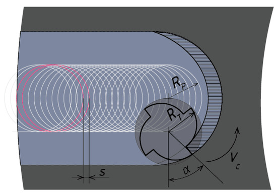
Figure 3.
Graphic presentation of trochoidal parameters: s—step of trochoid; RP—radius of the trochoid circle; RT—radius of the milling cutting tool; α—engagement angle.
When we use trochoidal milling, there are two next parameters (step of trochoid and engagement angle) which define the trochoidal path. Due to this fact, the research of the trochoidal path has been focused on the step of trochoid, the engagement angle and trochoidal radius (Figure 3).
The trochoid step determines the distance between the centres of two adjacent circles that characterize the tool’s feed by a given distance. The engagement angle is the angle of stroke that occurs between the two directions at the tool and material contact point. Between two mentioned parameters, there is a relationship which causes the curvature of the path. During the path generation, the CAM system continuously checks the engagement angle at each tool position defined by the step. If the engagement angle is greater than the specified value, the cutting tool at this position performs a circular tool movement with the radius defined by the radius parameter. If the engagement angle is smaller than the specified value, the CAM system does not generate a circular movement at this position; the tool moves to the next position. The trochoid radius is the radius of the circle describing the rolling motion of the milling cutting tool, the centre of the tool as the centre of the actual trochoid circle moving along a solid baseline. The walls of the formed groove are not entirely straight; they have the shape of small circular arcs; the surface quality of the groove wall increases with the set step and the radius of the trochoid. The magnitudes of the forces acting on the milling cutting tool correspond to the magnitudes of the forces-responses of the milling cutting tool acting on the machined material, in accordance with the Newton’s third law [5,9,29]. The aim of the research of the dynamics of the trochoidal machining process is to examine the dependence of the total machining force on the trochoid parameters qualitatively and quantitatively. At a relatively small engagement angle, the area of the workpiece material cut width is reduced. If the currently machined surface is theoretically reduced to a single point, the tangent at this point is a common tangent to the radius of the milling cutting tool and to the radius of the current trochoid circle. Practically, however, it is never the case of a single point, but always of a machined surface; therefore, it also depends on the ratio of the radius of the cutting tool and the radius of curvature of the trochoid curve. The follow-up research of the total machining force, depending on the radius of the trochoid curve, is also fundamental, in the context of the dependence on the step and engagement angle.
In the presented paper, a groove of the desired width and depth (Figure 4) is milled using the trochoidal milling technique to examine the machining forces, depending on the change of the two selected parameters that can be set via CAM interface; namely, the step and the engagement angle. When examining the effect of the parameters on the total machining force, a simpler type of trochoidal milling was selected, which is relatively unloaded by other effects of non-linear movements of the centre of the tool. The radius of the trochoid is defined by the radius of each circular arc of the trochoidal trajectory, the number and density of the circular arcs being determined by the trochoid step.
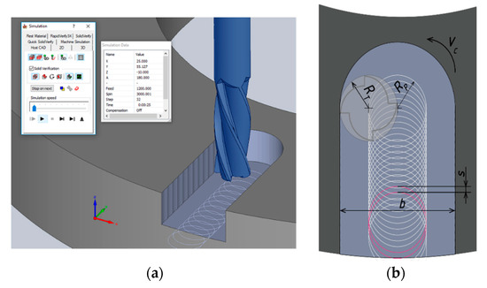
Figure 4.
Diagram of the presented method of trochoidal grooving according to SolidCAM: (a) presentation of GUI of SolidCAM; (b) orthogonal view of trochoidal milling path, where: RT—radius of the milling cutting tool; RP—radius of the trochoid circle; b—width of the milled groove; s—trochoid step.
1.2.4. Cutting Forces in Trochoidal Milling
The total machining force F is the action force the tool exerts on the workpiece and at which it is pressed into the machined material. The machined material exerts an equally large and inversely oriented resistive reaction force on the tool. The total machining force is the resultant one of the two components, namely, the active component Fa and the passive component Fp, but in principle, it does not act in a simplified manner in the 2D space; it acts in the general direction and can be divided into three mutually perpendicular directions in the 3D space. The feed component Ff acts in the x axis; the normal component Ffn acts in the y axis as a normal to the feed component; and the passive component Fp acts in the z axis (Figure 5). The active force component Fa can be considered the result of the cutting component Fc and its normal Fcn, and at the same time, as the result of the feed component Ff and its normal Ffn.
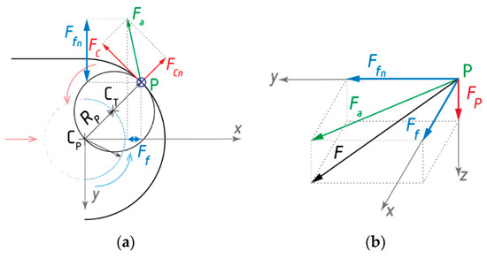
Figure 5.
Scheme of the components for total machining force F: in 2D-plan (a) and 3D-side (b) views.
Machining force components can be measured indirectly; for example, from the power output of the machine electric motor or the torque of the power relative to the rotation axis [7,30]. In the presented experiments, exact, direct measurements of the components of the total machining force were used using a stationary dynamometer, which measures the rectangular projections of the components of the forces Ff, Ffn and Fp in the 3D coordinate system axes x, y and z.
The active component of the force Fa is the cutting force, the largest and most important component of the machining force, acting in the general direction, so it cannot be measured directly by the dynamometer. However, its magnitude can be measured indirectly as the resultant of the feed component Ff (acting in the x axis direction) and the normal to the feed component Ffn (acting in the y axis direction). Knowledge of the active force component is a fundamental basis for calculating the stresses of the milling cutting tool and the workpiece chuck; and the energy balance of the machine tool. The component of the feed force Ff acts in the direction of the machine feed; its magnitude is mainly the basis for calculating the strength of the tool. The passive component of the force Fp is the smallest component of the machining power; in the case of trochoidal milling, the active force component is often more significant by orders of magnitude than the passive component, but the passive component has a high information value from the technological point of view. In principle, it pushes the tool out stroke with the workpiece, resulting in vibration during the machining process. The vibration is highly undesirable, primarily because it negatively affects the accuracy of the workpiece dimensions and the quality of the machined surface. Since the passive component is very small in the case of trochoidal machining, the cut is relatively stable.The presented results follow on from the current research of trochoidal milling and focus on the analysis of the course and character of the machining forces in the formation of the trochoid path using CAM software. Trochoidal milling is a dynamic machining method which, thanks to the use of the new CAM control systems, allows one to not only maintain constant cutting conditions (feed and angular speed of the cutting tool), but also the parameters of the trochoid, the step, the engagement angle, the mean chip thickness and the surface roughness of the workpiece. For each application and each tool, the cutting conditions and parameters of the trochoid must be optimized. The use of the trochoid grooving method places high demands on machine tools that must be able to provide sufficient acceleration to ensure the prescribed workpiece trajectory and have sufficient power to provide the requested speed.
2. Materials and Methods
The primary task of the experimental part of the research was trochoidal grooving of the steel by a vertical machine tool, with the setting of various parameters of the trochoidal path and continuous recording of the cutting forces by a stationary dynamometer to achieve knowledge about the influence of these parameters on a load of the cutting tool. As it was mentioned in the previous part, this research builds on previous analysis of tool wear due to cutting parameters. A summary of the research results is in Section 2.2.1.
2.1. Material and Technical Equipment
Material and technical equipment was based on a machining computer-controlled centre and precision instruments for measuring machine tool components when milling grooves in investigated samples from material which are hard to process.
2.1.1. Workpiece Material
The material EN X38CrMoV5-1, (commercially known as Bohler W300, Voestalpine Böhler Edelstahl GmbH & Co KG, Kabfenber, Austria) a tool steel designed for the production of forging dies, was selected for the experiments. This material was chosen because of its expansion in the manufacturing processes of cooperating partners (from practice), but also because of its widespread use in the industry dealing with forging and forming tools. Due to its high hardness of 58 HRC, this steel is usually used in professional practice for hot work due to its high resilience, high strength while hot, high strength and excellent air and vacuum hardenability. The machined sample was a forging die. Forging dies are used for dropping hammers, spindle and forging presses to make forgings from unalloyed, low alloy steels or light metal alloys. For the renovation of forging dies, different types of technology are used, among which, based on the presented experience, trochoidal milling can be included.
2.1.2. Milling Machine and Tool
For the trochoidal milling, the multifunction Hurco-VMX-30-T (Hurco Companies, Inc., Indianapolis, IN, USA) Vertical Machining Centre with Ultimax CNC control was used. The technical parameters of Hurco-VMX-30-T are listed in Table 1. The maximum revolutions available for working tool movements are 12,000 RPM with an output of 13.5 kW. Depending on the tool used and the material being machined, this limit is reduced to 6000 RPM. The machine has basic sensors placed in travels and the spindle, but only for internal load control in the machine control system environment.

Table 1.
Technical parameters of the used machine Hurco VMX-30-T.
According to the workpiece material, which exhibits a hardness of 58 HRC, the UNIFR41010xR1 milling cutting tool (5 mm radius, Figure 6) was used for the experiments, which is designed for high-speed machining of hardened steels with a hardness of up to 70 HRC. The selected milling tool has four flutes with irregular helices (angles 35°and 38°) having a significant effect on controlling vibration when compared to standard end mills. This cutting tool fully complied with the recommended cutting conditions by the manufacturer and the experimental conditions.
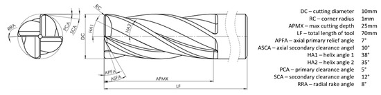
Figure 6.
Milling tool: schematic presentation of geometry.
This end mills cutting tool uses the technology of nanocrystal coating for higher hardness, higher speed and longer tool life due to the higher coating hardness and heat resistance. During the machining of the workpiece, it has a lower coefficient of friction and prevents abnormal damage. The features of this type of coating in comparison with other types are listed in Table 2.
Table 2.
The features of nanocrystal coating in comparison with other types.
2.1.3. Measurement of Cutting Forces
During milling, three perpendicular machining forces were measured with the stationary dynamometer mounted between the chuck platen and the workpiece.
It is a measuring device designed for machining purposes. In principle, it operates on the piezoelectric effect, when a mechanical load on the piezoelectric sensor generates an electrical charge on the surface of the measuring plate cut out of a special crystal. The dynamometer contains four sensors.
Each force sensor is piezoelectric. It has three components; i.e., it contains three crystal discs, each disc recording one force in the given direction, namely, the pressure and tensile force in the direction of the z axis (±Fz), and the positive and negative shear forces in both directions ±Fx and ±Fy, measuring three given orthogonal force components at the same time. For 3-component force measurements during milling, eight signals are obtained, which are summed up into a 3-wire cable and then lead to three charge amplifiers. The charge amplifier includes a capacitor, and by changing its range, it is possible to vary the measured force range. The amplified charge signal is converted to a voltage signal, which is evaluated. The size of the charge, or the electrical voltage, is proportional to the magnitude of the applied force. Software signal processing includes visualization and spreadsheet calculations. The technical parameters of the dynamometer used are shown in Table 3.
Table 3.
Basic technical data for the three-component piezoelectric dynamometer.
The dynamometer is used for direct measurement by the three components of the force Ff, Ffn and Fp, in which their magnitudes are measured in the directions of the coordinate x, y and z axes. Because they are rectangular projections of the component of the active force Fa and the passive component Fp into the coordinate axes in 3D space, the magnitude of the total machining force F had to be measured indirectly, i.e., calculated as the magnitude of the vector sum of the measured components Ff, Ffn and Fp according to (1), namely, for the number of partial measurements i = ⟨1, …, 125,500⟩.
The stationary dynamometer was connected to a computer by an A/D converter.
2.1.4. The Hardware and Software Used
The DAQ system DasyLab (version 13, Measurement Computing Corp., Norton, MA, USA, 2013) was used for computer data collection. DasyLab was as an environment suitable for laboratory measurement to enable efficient use of measuring and control hardware. The acquisition rate was 500 Hz. The obtained signal data were not filtered. In order to generate toolpaths for trochoidal machining, the SolidCAM program has been selected, which uses the investigated parameters (cutting angle and trochoid step) as the trochoid basic input parameters.
The Excel spreadsheet was selected for processing the measurement results, and the MatLab (version R2018b, MathWorks©, Natick, MA, USA) interactive programming environment was selected for the statistical and graphical evaluation of the results.
2.2. Design of Experiments
2.2.1. Previous Research—the Basis for Actual Research
The experiments presented in this article are part of the follow-up research carried out at the Department of Machining and Manufacturing Technology at the Faculty of Mechanical Engineering at the University of Zilina. This research was focused on the intensification of cutting parameters in the production and renovation of forging tools. The experiments carried out in the previous research were aimed at determining suitable cutting conditions with regard to adequate productivity.
During the experiments, the effects of cutting conditions on tool life and wear on the cutting tool were primarily monitored. The distribution of individual values was based on the DoE (design of experiments) principles; 3 measurements were determined to evaluate tool wear based on our own research, available works by reputable experts [31,32] and ISO 8688 [33] (milling tool testing). In the wear analysis, the 1st measurement was the identification measurement, the 2nd measurement was a comparative measurement, and the 3rd measurement was a verification measurement. Cutting speed values are based on the tool speed setting in the machine control program. Their range is set based on the characteristics of the machine, tool and workpiece, or real forging tools (identical to the current ones). In the table below (Table 4), the speed is recalculated to the cutting speed for a D10 diameter tool and the feed rate for a 4-tooth tool. The depth of cut was chosen as constant ap = 10 mm, for all experiments, taking into account the dimensions of the milling cutter and machined samples of the forging tool.
Table 4.
Three-level division of trochoidal milling experiments.
The critical wear limit (VBk – critical flank wear on the cutting tool) was determined with respect to tool geometry at VBk = 0.2 mm (evaluated critical flank wear on the cutting tool). Table 5 gives an overview of the machining times achieved when the critical wear value was exceeded, and the productivity was evaluated by the total material remove parameter during such times (as total material removed).
Table 5.
Tool life TVBk20 and material removal rate Q for experimental tests.
As can be seen from the measured values (Table 5), the longest machining times after reaching the critical wear value were at the lowest cutting speed experiments (Experiments P1 and P2). At the same time, these experiments also show the lowest productivity in terms of material removal when the tool has reached the critical wear value. This parameter was measured but was not primarily analysed and only had an auxiliary/support function in further analysis of the choice of suitable cutting parameters. When comparing the extremes of values, it can be stated that while the tool speed has increased 5-fold (from 1000 to 5000 RPM), tool wear has decreased to approximately 60%.
Taking into account the parameter of the total amount of material taken as well, the setting of experiment P4 seems to represent suitable cutting conditions. It can be assumed that by adjusting the trochoid path itself (and thus the tool load), the machining time can be extended up to 60 min with wear below the set value, since the measured wear values up to this time only slightly exceeded the critical wear parameter (up to time of 60 min, the maximum VB wear was at 0.21 mm).
The dependencies of the influences of the change in cutting speed and feed on the tool wear were created from the measured values, as shown in Figure 7. For clarity, they are classified according to the size of the cutting force.
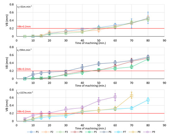
Figure 7.
The graphical course of tool wear at various cutting parameters of trochoid machining (see the Table 4 with conditions P1–P9)—classified by cutting force.
As can be seen from the chart, the cutting parameters have a significant impact on tool wear. The statistical evaluation shows that wear occurs earlier at higher speeds. It can be seen from the course of wear that conditions with mean values of cutting speed or revolutions prove to be suitable cutting parameters. At the same time, at the highest speeds (P8 and P9) and feeds, it was not possible to successfully complete the entire removal in all cases due to complete destruction of the cutting edge.
From the values obtained by repeating the tests, it can be seen that there were significant deviations between measurements, many of which exceeded 10%. Tool wear is significantly influenced not only by the cutting parameters, but also by tool clamping, or the rigidity of the entire machining system. However, the variations found in the individual experiments may be mainly due to material inhomogeneity (the influence of microstructure or internal errors resulting from the manufacture of the workpiece), which cannot be sufficiently filtered under current metrological procedures to make the machined material quasi-homogeneous. Based on the measured data and processed results, it was determined that further research would focus on the determination of the influence of trochoid parameters (step and engagement angle). Given parameters are in the CAM system as the basic parameters that affect the shape of trochoid itself. The trochoid shape has a direct effect on the current amount of material being cut by the milling cutter, thereby directly affecting the tool load, wear and ultimately the tool life. For the most accurate determination of the impact of the given parameters, it was specified that the usual cutting parameters, such as cutting speed and feed rate, would be constant. The depth of the cut remained unchanged compared to the previous experiment.
2.2.2. Setup of Actual Experiments
At the beginning of the experiments, the initial setting (in the SolidCAM program) was:
- Cutting speed as the circumferential speed of the milling cutting tool, vc = 94 m·min−1;
- Constant cutting conditions, namely, feed per tooth: fz = 0.1 mm;
- The depth of cut was identical to the depth of the groove;
- Dimensions of the machined groove (width 20 mm, length 55 mm, depth 10 mm) (Figure 8);
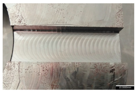 Figure 8. An example of a finished groove sample: the detail of one of the milled grooves with a noticeably higher surface waviness.
 - Trochoid radius Rp = 5 mm (the same for all experiments);
- Trochoid step s = 0.1, 0.6 and 1 mm (the same for three triples of experiments);
- Engagement angle α α= 10°, 30° and 60° (the same for three triples of experiments).
Selected trochoidal parameters were set according to DoE principles—response surface. As a potentially suitable model, we chose the central composite plan with three levels of adjustment.
A total of nine grooves were milled, with two varied parameters for each partial experiment: parameter s—trochoid step, and parameter α—engagement angle. The individual experiments were divided into three levels according to the 3-level plan (Table 6).
Table 6.
Three-level division of conventional trochoidal milling experiments.
During the milling of each groove, the components of the machining forces were measured and recorded. The procedure was repeated according to Table 6, with the same chip volume being taken for each groove.
3. Results and Discussion
3.1. Analysis of Results for the Computation of the Prediction Model
According to the 3-level plan (Table 6), nine grooves were milled on a sample of the same material, when changing the step and the engagement angle. The dynamometer was placed underneath the workpiece, and the cutting forces were measured in the XYZ system, with the milling cutter performing a motion related to the mathematical definition of trochoid, as shown in Figure 3 and Figure 5. The orientation of the tool relative to the reference system changed depending on the movement, which resulted in a change in the size of the cutting force components (projected into individual axes). At the same time, in the second part of the semicircle, the milling cutter was out of the engagement, which resulted in a “zero” load in the course of the components of the total cutting force. Based on the calculated path, the tool came into the engagement, which resulted in a change in the cutting force Ff (in the x axis’s direction). As the tool moved along the trochoid radius Rp, the force increased. As the tool shifted more in the y axis, the force component Ffn grew and the component Ff tended to decrease. The size of the component Fp reflected the entire toolpath in engagement. Research of cutting force, or of cutting force components realized by several experts [11,20,23,34,35,36] in the previous period, was focused mainly on the determination of the impact of tool movement on its load; the creation of mechanistic models; and, last but not least, identification of other impacts, such as machining vibrations. The detected dependencies make it possible to get an accurate idea of the current tool load. These factors were also taken into account when setting the dynamometer sensing frequency to identify the rotation of the tool and the influence of the load on the individual cutting edges of the tool in contact with the material (in engagement—in our case four teeth to four flutes) clearly. Since our research was focused on analysing the impacts of trochoid parameters on the overall tool load, the analysis was not performed using a chatter model, but through local toolmaking peaks for the individual tool passes and average values for these peaks. The data obtained from the development of the total cutting force components, as shown in Figure 9, served as the basis.
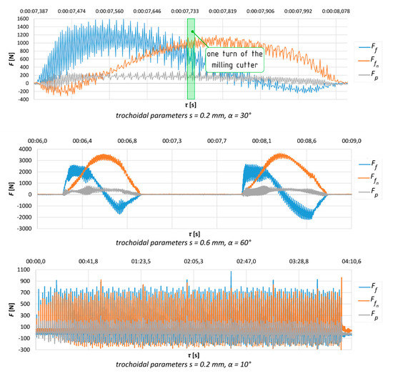
Figure 9.
Time recording of the evolution of the cutting force components for selected cases (top—detail of one pass; bottom—the progress as a whole).
These graphical outputs do not provide an overview of the trends of the investigated influences at a glance, because the resulting machining force cannot be directly measured; not even its active component can be directly measured. Only rectangular projections of the active and passive force components into the coordinate axes can be directly and precisely measured with the dynamometer. The active force of the total machining force can then be measured indirectly; i.e., it must be evaluated in each partial measurement as the vector sum of the components of the forces Ff and Ffn. The total machining force F can also be measured indirectly; i.e., it can be evaluated in each partial measurement as the vector sum of the components of the forces Fa, Fp (Table 7).
Table 7.
Indirectly measured maximum machining force Fmax by the vector sum of experimentally measured maximum force components.
3.2. Mathematical-Statistical Analysis for Measured Values
After the experiments and partial analyses of the measured results were finished, the experimental data were subjected to statistical analysis (Table 8).
Table 8.
The output from the analysis of variance for the total machining force F.
From the analysis of variance (Table 8) for the total machining force F, it follows that the most significant influence is shown by the engagement angle α, which directly affects the value of the maximum width of the removed layer, reaching up to 75.9% of the linear model. This fact is manifested above all in a more pronounced inclination in the direction of the s axis. From the scattering analysis, it also follows that, within a given range of cutting conditions, the response has a quadratic character in the direction of the s axis; i.e., approximately at the mean values of the step s, this force reaches its maximum.
The response area is defined as the second-degree polynomial. The precision of the presented model reaches 99%, with a prediction coefficient of 87.02% and a 95% confidence interval setting, or ±5% on both sides. In terms of the statistical significance of the individual members, this model can be considered correct and sufficiently accurate for further research, for simulation and verification of the machining process and for subsequent follow-up applications in professional practice.
The response area equation (Figure 10) shows the influence of the trochoid parameters: step s (mm) and engagement angle α (°), with the trochoid constant radius Rp = 5 mm; namely, the impact on the change in the total machining force F (2):
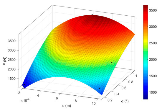
Figure 10.
Response area chart for the total machining force F.
3.3. Verification of the Prediction Model
Based on the determined calculation model, verification measurements of the set-up of experiments were performed (according to Table 6). A total of 18 experiments were performed, nine for modelling and nine for verification. The individual force components were measured during these experiments as a basis for evaluating the total cutting force of the machining. The resulting values were compared with those from the prediction model (Table 7).
In Table 9 is the comparison of values from measurements (total machining force Fmax was computed from indirect measurements of cutting forces) with predicted values—computed values of Fmax.
Table 9.
Comparison of statistically predicted magnitudes of the total machining force Fmax according to the predictive Equation (2) and measured the total machining Fmax.
Figure 11 shows the processed values of Table 9. As can be seen from the comparison of the predictive model values with those obtained from the verification measurement, the smallest deviation achieved in two cases (Experiments 3 and 5) was only 1%. In two cases, the highest deviation was higher than 5%; in other cases this limit was not exceeded, and it is possible to evaluate the prediction model as sufficiently accurate.
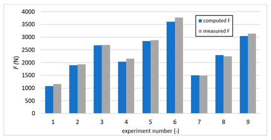
Figure 11.
Graphical comparison of predicted and measured values of total machining force F.
4. Conclusions (and Future Work)
The presented research aimed to analyse the impacts of trochoid parameters on the basis of the findings from our previous research on the influences of cutting parameters. After determining the influences, a mathematical-statistical prediction model was created and successfully verified based on the experimental settings.
On the basis of experimental results of direct measurements of the components of the machining forces with the dynamometer during the trochoidal milling of the groove in steel:
- The total machining force was measured and evaluated indirectly.
- The results of nine experiments performed for combinations of three different trochoid step settings and three different settings of the engagement angle at constant trochoid radius were processed statistically, and the predictive equation of the total machining force and the corresponding response area of the total machining force were created.
- Both the response area and the comparative regression equation of the total machining force, dependent on the trochoid step and on the engagement angle, indicate that the influence of the trochoid step is parabolic, and the influence of the engagement angle is linear with the constant radius of the trochoid.
The limitations of the achieved model are mainly in the material and tools used, but they were chosen based on practical requirements.
Knowledge of the predictive equation of the machining force will make it possible to decide more effectively about the settings of the input parameters of the trochoidal milling and the technological conditions of this setting. The resulting benefits of the presented results can be seen in the creation of material for further predictions; namely, for the prediction of milling cutting tool wear and the prediction of the quality of the machined surface.
The novelty of the presented paper is the creation of a model determining the influence of trochoidal parameters on tool loading. The research outputs are intended for real deployment for the setting of trochoid parameters (step and engagement angle) in order to simplify their settings in the programming phase in the environment of CAM systems. Based on the cooperation of the companies participating in the research (named in the Featured Application section), the outputs were successfully implemented in real production.
Trochoidal milling is a method applicable to a wide range of materials, in particular, those with reduced machinability, and wherever major material removal is required in the shortest possible time. Based on the findings, it can be concluded that the prediction model obtained has the potential for further refinement for other tools and materials.
Author Contributions
Conceptualization A.C. and J.V.; data curation A.C. and M.Š.; resources M.H. and M.B.; methodology J.V., M.Š. and M.K.; investigation M.Š. and M.D.; formal analysis M.Š., M.K., T.C. and M.B.; funding acquisition A.C, T.C.; writing—original draft M.Š, M.K, M.B.; writing—review and editing J.V., M.H. and J.K.; validation M.K., J.V. and M.H. All authors have read and agreed to the published version of the manuscript.
Funding
This article was funded by research project APVV 15-0405 at the University of Žilina—“Complex use of X-ray diffractometry for identification and quantification of functional properties of dynamically loaded structural elements from important technical materials.”
Conflicts of Interest
The authors declare no conflict of interest.
Nomenclature
| ap | depth of cut | (mm) |
| APMX | max cutting depth angle on the milling tool | (%) |
| ASCA | axial secondary clearance angle on the milling tool | (mm) |
| b | width of the milled groove | (mm) |
| CP | centre of the trochoid circle | (mm) |
| CT | centre of the milling cutting tool | (mm) |
| DC | cutting diameter on the milling tool | (mm) |
| fz | feed per tooth | (mm) |
| Fa | an active component of the total machining force F as the result of the cutting FC and the pressure component FCn in a general direction, which cannot be directly measured; also, this force is the resultant magnitude of the measured rectangular projections of the force components Ff and Ffn | (N) |
| FC | cutting force as a component of the active force Fa of the general direction, which cannot be directly measured, lies in a tangent perpendicular to the radius of the milling cutting tool at point | (N) |
| FCn | pressure force as a normal for cutting force, a component of the active force Fa of general direction, which cannot be directly measured | (N) |
| Ff | rectangular projection of the active component of the total machining force into the x axis directly measured by a dynamometer | (N) |
| Ffn | rectangular projection of the active component of the total machining force into the y axis directly measured by a dynamometer | (N) |
| HA1 | helix primary angle on the milling tool | (°) |
| HA2 | helix secondary angle on the milling tool | (°) |
| LF | the total length of the tool on the milling tool | (°) |
| P | machined surface reduced to the contact point of the milling cutting tool and the workpiece material; | (–) |
| PCA | primary clearance angle on the milling tool | (°) |
| Q | material removal rate per time unit | (cm3⋅min−1) |
| QT | the total quantity taken over time after the specified wear has been achieved | (cm3) |
| RC | corner radius on the milling tool | (mm) |
| RP | radius of the trochoid circle (part of the trochoid circle is in blue; the direction of the trochoid circle rotation is a blue arrow, and the direction of the feed of the trochoid circle centre is a red arrow) | (mm) |
| RRA | radial rake angle on the milling tool | (°) |
| RT | radius of the milling cutting tool (the milling tool circumference is in black, and the milling and cutting tool rotation directions are in red) | (mm) |
| s | trochoid step | (mm) |
| t | time (when measured tool wear) | (min.) |
| TVBk20 | tool life on the basis of specified wear VBk = 20 μm | (min.) |
| SCA | secondary clearance angle on the milling tool | (°) |
| vc | cutting speed | (m∙min−1) |
| VBk | evaluated critical flank wear on the cutting tool | (mm) |
| x | the direction of the coordinate axis of the cutting plane | (-) |
| y | the direction of the coordinate axis of the cutting plane | (-) |
| α | engagement angle in computing of trochoidal path | (°) |
| τ | time (when measured cutting forces) | (s) |
| ⨂ | the mark at point P as a symbolic representation of the direction in the z axis (perpendicularly below the xy plane) of the vector FP of the passive component of the total machining force F | (-) |
References
- Waszczuk, K.; Skowronek, H.; Karolczak, P.; Kowalski, M.; Kolodziej, M. Influence of the Trochoidal Tool Path on Quality Surface of Groove Walls. Adv. Sci. Technol. Res. J. 2019, 13, 38–42. [Google Scholar] [CrossRef]
- de Lacalle, L.N.; Lamikiz, A.; Munoa, J.; Salgado, M.A.; Sanchez, J.A. Improving the high-speed finishing of forming tools for advanced high-strength steels (AHSS). Int. J. Adv. Manuf. Technol. 2006, 29, 49–63. [Google Scholar] [CrossRef]
- Ning, J.; Nguyen, V.; Liang, S.Y. Analytical modeling of machining forces of ultra-fine-grained titanium. Int. J. Adv. Manuf. Technol. 2019, 101, 627. [Google Scholar] [CrossRef]
- Ning, J.; Nguyen, V.; Huang, Y.; Hartwig, K.T.; Liang, S.Y. Inverse determination of Johnson–Cook model constants of ultra-fine-grained titanium based on chip formation model and iterative gradient search. Int. J. Adv. Manuf. Technol. 2018, 99, 1131–1140. [Google Scholar] [CrossRef]
- Santhakumar, J.; Mohammed Iqbal, U. Parametric Optimization of Trochoidal Step on Surface Roughness and Dish Angle in End Milling of AISID3 Steel Using Precise Measurements. Materials 2019, 12, 1335. [Google Scholar] [CrossRef]
- Krahmer, D.M.; Hameed, S.; Sanchez, A.J.E.; Perez, D.; Canales, J.; de Lacalle, L.N. Wear and MnS Layer Adhesion in Uncoated Cutting Tools When Dry and Wet Turning Free-Cutting Steels. Metals 2019, 9, 556. [Google Scholar] [CrossRef]
- Liu, D.; Ying, Z.; Luo, M.; Zhang, D. Investigation of Tool Wear and Chip Morphology in Dry Trochoidal Milling of Titanium Alloy Ti–6Al–4V. Materials 2019, 12, 1937. [Google Scholar] [CrossRef] [PubMed]
- Polvorosa, R.; Suárez, A.; López de Lacalle, L.N.; Cerillo, I.; Wretland, A.; Veiga, F. Tool wear on nickel alloys with different coolant pressures: Comparison of Alloy 718 and Waspaloy. J. Manuf. Process. 2017, 26, 44–56. [Google Scholar] [CrossRef]
- Krahmer, D.M.; Polvorosa, R.; López de Lacalle, L.; Alonso, U.; Abate, G.; Riu, F. Alternatives for Specimen Manufacturing in Tensile Testing of Steel Plates. Exp. Tech. 2016, 40, 1555–1565. [Google Scholar] [CrossRef]
- Xu, K.; Wu, B.; Li, Z.; Tang, K. Time-Efficient Trochoidal Tool Path Generation for Milling Arbitrary Curved Slots. J. Manuf. Sci. Eng. 2019, 141, 031008. [Google Scholar] [CrossRef]
- Pleta, A.; Ulutan, D.; Mears, L. Investigation of Trochoidal Milling in Nickel-Based Superalloy Inconel 738 and Comparison with End Milling. In ASME 2014 International Manufacturing Science and Engineering Conference Collocated with the JSME 2014, Proceedings of the International Conference on Materials and Processing and the 42nd North American Manufacturing Research Conference, Detroit, MI, USA, 9–13 June 2014; American Society of Mechanical Engineers: New York, NY, USA, 2014. [Google Scholar]
- Bettine, F.; Ameddah, H.; Manna, R. A Neural Network Approach for Predicting Kinematic Errors Solutions for Trochoidal Machining in the Matsuura MX-330 Five-Axis Machine. FME Trans. 2018, 46, 453–462. [Google Scholar] [CrossRef]
- Pleta, A.; Nithyanand, G.; Niaki, F.A.; Mears, L. Identification of optimal machining parameters in trochoidal milling of Inconel 718 for minimal force and tool wear and investigation of corresponding effects on machining affected zone depth. J. Manuf. Process. 2019, 43, 54–62. [Google Scholar] [CrossRef]
- Kechagias, J.D.; Aslani, K.-E.; Fountas, N.A.; Vaxevanids, N.M.; Manolakos, D.E. A comparative investigation of Taguchi and full factorial design for machinability prediction in turning of a titanium alloy. Measurement 2020, 151, 107213. [Google Scholar] [CrossRef]
- Li, Y.; Zheng, G.; Zhang, X.; Xu, R. Cutting force, tool wear and surface roughness in high-speed milling of high-strength steel with coated tools. J. Mech. Sci. Technol. 2019, 33, 5393. [Google Scholar] [CrossRef]
- Djurdjanovic, D.; Mears, L.; Niaki, F.A.; Haq, A.U.; Li, L. State of the art review on process, system, and operations control in modern manufacturing. J. Manuf. Sci. Eng. 2017, 140, 061010. [Google Scholar] [CrossRef]
- Li, Z.; Xu, K.; Tang, K. A new trochoidal pattern for slotting operation. Int. J. Adv. Manuf. Technol. 2019, 102, 1153. [Google Scholar] [CrossRef]
- Saleem, W.; Ijaz, H.; Alzahrani, A.; Asad, M.; Zhang, J. Numerical modeling and simulation of macro- to microscale chip considering size effect for optimum milling characteristics of AA2024T351. J. Braz. Soc. Mech. Sci. Eng. 2019, 41, 337. [Google Scholar] [CrossRef]
- Amaro, P.; Ferreira, P.; Simoes, F.C.K. Tool wear analysis during duplex stainless steel trochoidal milling. AIP Conf. Proc. 2018, 1960, 070001. [Google Scholar] [CrossRef]
- Niaki, F.A.; Michel, M.; Mears, L. State of health monitoring in machining: Extended Kalman filter for tool wear assessment in turning of IN718 hard-to-machine alloy. J. Manuf. Process. 2016, 24, 361–369. [Google Scholar] [CrossRef]
- Zhang, H.T.; Wu, Y.; He, D.; Zhao, H. Model predictive control to mitigate chatters in milling processes with input constraints. Int. J. Mach. Tools 2016, 91, 54–61. [Google Scholar] [CrossRef]
- Karagiannis, S.; Stavropoulos, P.; Ziogas, C.; Kechagias, J. Prediction of surface roughness magnitude in computer numerical controlled end milling processes using neural networks, by considering a set of influence parameters: An aluminium alloy 5083 case study. J. Eng. Manuf. 2014, 228, 233–244. [Google Scholar] [CrossRef]
- Pleta, A.; Ulutan, D.; Mears, L. An Investigation of Alternative Path Planning Strategies for Machining of Nickel-Based Superalloys. Procedia Manuf. 2015, 1, 556–566. [Google Scholar] [CrossRef][Green Version]
- Niaki, F.A.; Pleta, A.; Mears, L. Trochoidal Milling: Investigation of a New Approach on Uncut Chip Thickness Modeling and Cutting Force Simulation in an Alternative Path Planning Strategy. Int. J. Adv. Manuf. Technol. 2018, 97, 641–656. [Google Scholar] [CrossRef]
- Pleta, A.; Mears, L. Cutting Force Investigation of Trochoidal Milling in Nickel-Based Superalloy. Procedia Manuf. 2016, 5, 1348–1356. [Google Scholar] [CrossRef]
- Banerjee, A.; Feng, H.Y.; Bordatchev, E.V. Geometry of Chip Formation in Circular End Milling. Int. J. Adv. Manuf. Technol. 2012, 59, 21–35. [Google Scholar] [CrossRef]
- Zhang, X.H.; Peng, F.Y.; Qiu, F.; Yan, R.; Li, B. Prediction of Cutting Force in Trochoidal Milling Based on Radial Depth of Cut. Adv. Mat. Res. 2014, 852, 457–462. [Google Scholar] [CrossRef]
- Nguyen, H.T.; Hsu, Q.C. Surface Roughness Analysis in the Hard Milling of JIS SKD61 Alloy Steel. Appl. Sci. 2016, 6, 172. [Google Scholar] [CrossRef]
- Yan, R.; Li, H.; Peng, F.; Tang, X.; Xu, J.; Zeng, H. Stability Prediction and Step Optimization of Trochoidal Milling. ASME J. Manuf. Sci. Eng. 2017, 139, 091006. [Google Scholar] [CrossRef]
- Zagorski, I.; Kulisz, M.; Klonica, M.; Matuszak, J. Trochoidal Milling and Neural Networks Simulation of Magnesium Alloys. Materials 2019, 12, 2070. [Google Scholar] [CrossRef]
- Brinksmeier, E.; Preuss, W.; Riemer, O.; Rentsch, R. Cutting forces, tool wear and surface finish in high speed diamond machining. Precis. Eng. 2017, 49, 293–304. [Google Scholar] [CrossRef]
- Finkeldey, F.; Hess, S.; Wiederkehr, P. Tool wear-dependent process analysis by means of a statisticalonline monitoring system. Prod. Eng. Res. Devel. 2017, 11, 677–686. [Google Scholar] [CrossRef]
- STN ISO. 8688-2 Metal-cutting tools. Tool life testing in milling. In End Milling; SUTN: Bratislava, Slovakia, 1993. [Google Scholar]
- Urbikain, G.; Olvera, D.; López de Lacalle, L.N.; Beranoagirre, A.; Elías-Zuñiga, A. Prediction Methods and Experimental Techniques for Chatter Avoidance in Turning Systems: A Review. Appl. Sci. 2019, 9, 4718. [Google Scholar] [CrossRef]
- Urbikain, G.; Olvera, D.; López de Lacalle, L.N.; Beranoagirre, A.; Elías-Zuñiga, A. Spindle speed variation technique in turning operations: Modeling and real implementation. J. Sound Vib. 2016, 383, 384–396. [Google Scholar] [CrossRef]
- Altintas, Y. Critical Review of Chatter Vibration Models for Milling. In Autonome Produktion; Klocke, F., Pritschow, G., Eds.; Springer: Berlin/Heidelberg, Germany, 2004. [Google Scholar]
© 2020 by the authors. Licensee MDPI, Basel, Switzerland. This article is an open access article distributed under the terms and conditions of the Creative Commons Attribution (CC BY) license (http://creativecommons.org/licenses/by/4.0/).