Abstract
Prestressed hollow core slabs (PHCSs) have commonly been applied to long-span structures, due to their excellent flexural capacity and deflection control performance. However, in quite a few cases, the web-shear strength at member ends subjected to high shear forces is insufficient, because the web of the PHCS is very thin, making it difficult to place shear reinforcement, and the prestress is not fully effective in transfer length regions. Accordingly, a variety of shear strengthening methods have been proposed to improve the web-shear strength of PHCS ends. In this study, experimental research was conducted to investigate the shear resistance mechanism of PHCS strengthened by core-filling method, which has been most widely used in the construction field. The number of filled cores and the shear reinforcement ratio were set as the main test variables, and the patterns and angles of shear cracks that occurred in the PHCS units and filled cores, respectively, and the strain behavior of the shear reinforcement, were measured and analyzed in detail. This study also analyzed the test results based on the current design codes, and proposed a modified shear strength equation that can be applied to the core-filled PHCS.
1. Introduction
Prestressed hollow core slabs (PHCSs) can reduce self-weight due to the presence of voids in the section, and because they are prefabricated in a factory as precast members, ensure excellent quality and reduced construction duration [1,2,3,4]. In addition, PHCSs exhibit high flexural strength and excellent deflection control performance because prestressing strands are placed in the bottom flange of the member, and consequently they are widely applied to long-span structures [5,6,7,8].
However, due to the characteristics of the PHCS, which has a large void ratio, the web is very thin, and the prestress is not fully effective in the transfer length region which results in a lack of web-shear strength at the member ends subjected to high shear forces [9,10,11,12,13,14]. Hawkins and Ghosh (2006) [13] reported that the thicker the depth of the PHCS, the lower the web-shear strength, and thus an additional strength reduction factor should be applied to ensure adequate safety for PHCS with a thickness greater than 315 mm. The ACI 318-08 [15] code, reflecting their findings, stipulates that the web-shear strength of PHCS with a thickness of more than 315 mm without minimum shear reinforcement should be reduced to half of the design shear strength () calculated using a code equation, and this also applies to the ACI 318-14 [16] code. In particular, since shear reinforcement cannot be placed in PHCS manufactured by using the extrusion method, the case of deep PHCS with a thickness greater than 315 mm can lead to very uneconomic design results.
Many previous researchers [3,4,5,6,7,8,9,10,11,12,13,14] have made various attempts to increase web-shear strength without using shear reinforcement, and examined the rationality of the additional strength reduction factor for deep PHCS members specified in the design code. Lee et al. [5] and Park et al. [6] collected many web-shear test results on PHCS, based on which they pointed out that the additional strength reduction factor (0.5) specified in ACI 318-14 [16] can provide excessively conservative design results. In addition, Lee et al. [5] performed a regression analysis and suggested a simplified equation to accurately estimate the web-shear strength of PHCS, regardless of the thickness of the member, even if the additional strength reduction factor is not taken into account. Brunesi and Nascimbene [17] conducted finite element (FE) analysis to identify the shear stress distributions and crack patterns of PHCSs according to member heights and section details including void shapes. From their analysis results, it is found that the shear stress distribution is sensitive with respect to the section shapes of PHCSs, and it is adequate to apply the fracture mechanics approach for the analysis of shear crack propagation. Girhammar and Pajari [18] carried out pull-off and shear tests of PHCS composites with topping concrete, based on which they analyzed the shear strengthening effect of topping concrete considering the bond strength between the PHCS unit and the topping concrete. In their analysis, the shear strength of the PHCS with a thickness of 200 mm increased up to 35% when topping concrete was cast with a thickness of 80 mm, and it matched well with the test results. Nguyen et al. [19] reported shear test results of four deep PHCSs with heights ranging from 320 to 500 mm and established FE model to simulate their shear behavior. However, the results of FE analysis were very sensitive, depending on the dilation angle used in their concrete damage plasticity model.
In overall, there are many empirical and numerical approaches to accurately estimate the shear behavior and strength of PHCSs, and they contributed to the better understanding of the shear resistance mechanism of PHCSs. However, a few studies have been conducted on the shear behavior of PHCSs strengthened by core-filling concrete. Investigating the shear strengthening effect of the core-filling method is very important because it has been widely applied as a shear strengthening method of PHCSs in construction fields due to its simple working process [12,20,21]. Table 1 shows the shear strength equations for reinforced concrete (RC) and prestressed concrete (PSC) members specified in the current design codes [16,22,23]. In practice, the shear contribution of concrete () of the PHCS with core-filling concrete is often simply calculated as , but in that case, the could be overestimated.

Table 1.
Code equations for estimating shear strength of reinforced concrete (RC) and prestressed concrete (PSC) members.
Palmer and Schultz [12] conducted web-shear tests on 400 mm thick PHCS strengthened by the core-filling method, and analyzed the web-shear strength equation presented in ACI 318-05 [24]. Note that there is no provision for the additional strength reduction factor (0.5) in ACI 318-05. Based on their test results, Palmer and Schultz reported that when calculating the web-shear strength of PHCS with filled cores, the shear contribution of the filled cores should be reduced by as much as 50% of the shear strength calculated using a code equation, in order to obtain accurate analysis results. That is, it turned out that the filled cores made a partial contribution to the shear strength of the member but failed to achieve 100% of their shear capacity in the test. On the other hand, Hegger et al. [25] performed shear tests of PHCSs applied in a slim floor system, in which two specimens were reinforced with core-filling concrete. In their tests, however, the shear strengths of the PHCSs did not increase by the core-filling concrete.
As mentioned above, previous researchers reported different test results on the shear strength of PHCS with filled cores, which is considered to be because of a very different bond condition, often poor, between the PHCS unit and filled cores. Thus, it is very hard to estimate the shear strengthening effect of the core-filling method. In structural design codes, such as ACI 318-14 [16], CSA-A23.3-14 [22], and Eurocode2 [26], estimating the shear strength of PHCSs with core-filling concrete is not provided.
In this study, experimental research was carried out to investigate the shear resistance mechanism of PHCS strengthened by the core-filling method. A total of five PHCS specimens with a thickness of 400 mm was fabricated by using the extrusion method, in which a machine extrudes low-slump concrete and compacts it to form a hollowed section along the long-line prestressing bed. The main test variables were set to the number of filled cores and the shear reinforcement ratio. During the test, the member behavior and crack patterns of PHCS specimens were measured in detail.
After the test, the members were cut with a wire saw to observe the crack patterns that occurred in the filled cores, and to identify whether the filled cores effectively contributed to the shear resistance mechanism. Based on the test results, this study also examined whether the current design codes adequately evaluate the shear strengths of PHCS with filled cores, and proposed a modified equation to accurately estimate the shear strengths of PHCS members strengthened by the core-filling method.
The significance of this research is summarized, as follows:
- Investigating the shear reinforcing effect of core-filling concrete.
- Identifying the effects of shear reinforcement placed in core-filling concrete.
- Investigating the composite action between the PHCS unit and core-filling concrete by observing their shear crack patterns.
- Developing a simple equation to accurately estimate the shear strengths of PHCS reinforced by the core-filling method.
2. Test Program
In this study, five PHCS specimens with a thickness of 400 mm were fabricated as shown in Table 2 and Figure 1. The width of the PHCS unit () was 1200 mm, the width of one web () was 55.2 mm, the total width of the web () was 276 mm, and the void ratio was 56%. Eleven prestressing strands with a diameter of 12.7 mm were placed in the lower part of the section, while three 9.5 mm diameter strands were laid in the upper part of the section, to control the tensile stress generated during the introduction of prestress. As shown in Table 2, the first character in the names of the specimen indicates a shear reinforcement ratio (). NR is a specimen without shear reinforcement. LR means a specimen with a relatively low (i.e., ), while HR means a specimen with a relatively high (i.e., ). The number that follows is the ratio of the number of filled cores to the number of entire cores. For example, LR-2/4 represents a specimen in which two of the four voids are filled with normal strength concrete.

Table 2.
Details of test specimen.
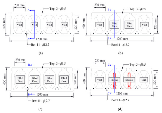
Figure 1.
Section details of test specimens. (a) NR—0/4 specimen. (b) NR—2/4 specimen. (c) NR—4/4 specimen. (d) LR—2/4 and HR—2/4 specimens.
The tensile strength () of the prestressing strands used in the specimens was 1860 MPa, and the effective prestress introduced into the PHCS unit was approximately 1200 MPa, which was about 65% of . Figure 1b–d shows that the top flanges were opened, and in-filled concrete was casted in the specimens, except for the reference specimen (NR-0/4). In addition, as shown in Figure 2, the core-filling concrete was placed for the position of the section, which is up to 1500 mm away from both ends of the member. Table 3 shows the mix proportions of the PHCS unit and the core-filling concrete. The concrete compressive strengths of the PHCS unit () and filled cores () were 66.0 and 25.1 MPa, respectively, which were measured from cylinder tests.
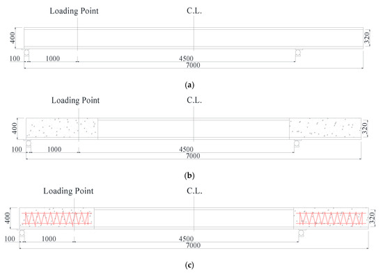
Figure 2.
Longitudinal section views of test specimens. (Unit: mm). (a) A-A section of the NR—0/4 specimen. (b) B-B section of NR—2/4 and NR—4/4 specimens. (c) C-C section of LR—2/4 and HR—0/4 specimens.

Table 3.
Mix proportions of concrete.
Figure 3 shows the details of helix shear reinforcement in LR-2/4 and HR-2/4 specimens. The amount of shear reinforcement was determined to be more than the minimum shear reinforcement ratio () specified in ACI 318-14 [16], where was calculated as below:
where, is the yield strength of the shear reinforcement, which was 400 MPa. The minimum shear reinforcement ratio () calculated using Equation (1) was 0.127%, and the diameters of shear reinforcements placed in LR-2/4 and HR-2/4 specimens were 8 and 12 mm, which correspond to the reinforcement ratios () 0.175% and 0.395%, respectively.
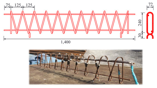
Figure 3.
Details of shear reinforcement. (Unit: mm).
Figure 4 shows the specimen loading details. In this study, the length () of the PHCS specimen was 7000 mm, and shear tests were conducted on both ends of the member. In other words, two shear test results were obtained for each specimen. In the shear test, the lengths of the left and right shear spans were set differently to induce shear failure in the transfer length region. The shear span-to-depth ratio () was 2.78, and a concentrated load was applied on the top of the specimens at 1000 mm away from the inner end of the supporting plate with a loading rate of 1.0 mm/min. In order to measure the deflection of the specimens, a linear variable differential transformer (LVDT) was installed at the bottom of the section located at the loading point. In addition, the shear contributions of the helix reinforcements in LR-2/4 and HR-2/4 specimens were measured from the strain gauges. As shown in Figure 5, the gauge attachment locations were determined by considering three crack patterns that can occur in the shear span [4,22,26,27]: (1) the straight line that makes an angle of 35° to the member axis from the support; (2) the straight line that connects from the support to the loading point; and (3) the straight line from the bottom of the critical section, which is distance from the support, to the loading point [22].
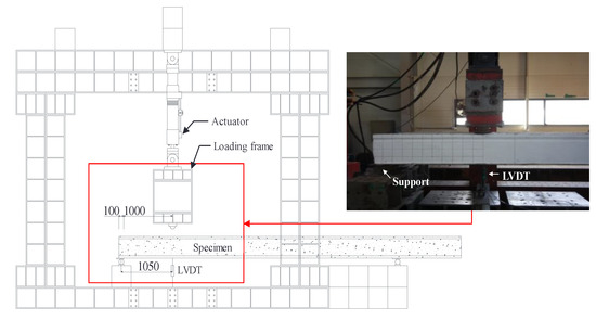
Figure 4.
Test setup (Unit: mm).
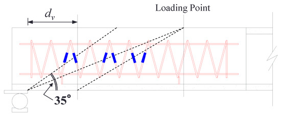
Figure 5.
Locations of strain gauges.
3. Test Results
3.1. Load-Displacement Behavior and Shear Strengths of Test Specimens
Figure 6a compares the behavior of NR-0/4, NR-2/4, and NR-4/4 specimens to analyze the shear reinforcement effects according to the number of filled cores. Since two tests were performed at both ends for each specimen, the first and second tests were distinguished by adding ‘(1)’ and ‘(2)’ after the specimen name. Figure 6b–d shows crack patterns observed from each specimen, while the numbers shown in Figure 6c,d indicate the order in which the cracks occurred with increasing loads. As shown in Figure 6a, the initial stiffness of the NR-0/4, NR-2/4, and NR-4/4 specimens was almost similar with and without filled cores, and the NR-0/4 (1) and (2) specimens underwent brittle failure simultaneously when web-shear cracking occurred at shear forces of 351.0 and 331.0 kN, respectively (341.0 kN on average). In the case of the NR-2/4 (1) and (2) specimens with two hollow cores strengthened by normal strength concrete, the stiffness started to decrease when flexural cracks occurred prior to the shear cracking; and these specimens showed shear failure as web-shear cracks occurred at the shear forces of 472.0 and 451.2 kN, respectively (461.6 kN on average). The NR-4/4 (1) and (2) specimens in which all the hollow cores of the PHCS unit were strengthened by in-fill concrete showed a sharper decrease in stiffness, as compared to the NR-2/4 specimens, after the flexural cracks were observed, and they underwent web-shear failure at the shear forces of 426.9 and 422.3 kN, respectively (24.6 kN on average).
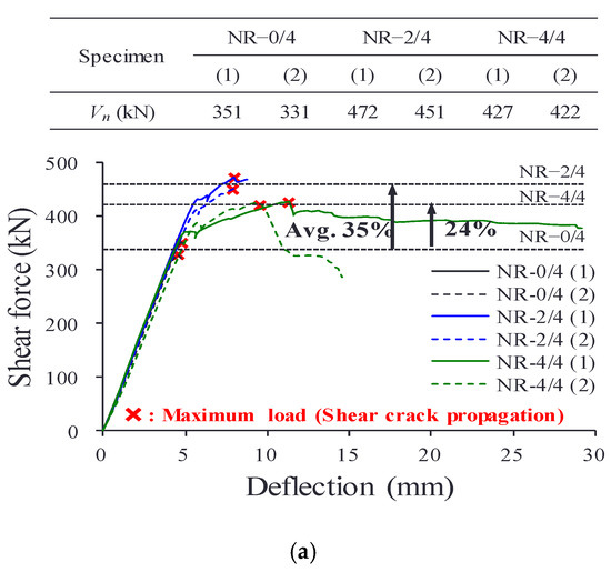
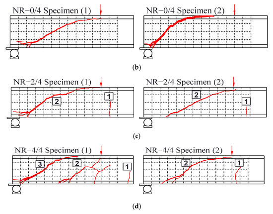
Figure 6.
Effect of filled cores on shear strength of prestressed hollow core slab (PHCS). (a) Shear force-deflection responses. (b) Crack patterns of the NR-0/4 specimen. (c) Crack patterns of the NR-2/4 specimen. (d) Crack patterns of the NR-4/4 specimen.
Table 4 compares the shear strengths of the specimens. The shear strengths of the NR-2/4 (1), (2), and NR-4/4 (1), (2) specimens increased by 32%–38% and 24%–25%, respectively, compared to the shear strength of the NR-0/4 specimen. However, in the case of the NR-4/4 specimen, with all four hollow cores strengthened, the shear reinforcement effect was smaller than that of the NR-2/4 specimen. This is because as shown in Figure 7, the web of the PHCS unit at the edge of the NR-4/4 specimen was separated from the filled core before reaching the ultimate load, and failed to resist external shear forces. The crack in the interface between the PHCS unit and the filled core initially occurred near the top flange opened for core-filling, and spread towards the bottom of the section along the interface. Figure 7b shows that at the time of shear failure of the member, the PHCS unit, and filled core were completely separated. Despite this, considering the fact that the PHCS units are continuously placed in an actual construction site, and cast-in-place concrete or non-shrink mortar is poured between the members, the separation of the PHCS unit web from the filled core would be delayed. However, additional experimental research is needed to verify such estimation.

Table 4.
Cracking loads and web-shear strengths of test specimens.
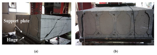
Figure 7.
Crack patterns of the NR-4/4 specimen at ultimate load. (a) Web-shear cracks. (b) Separation between PHCS unit and filled cores.
Figure 8 compares the shear force–deflection responses of the NR-2/4, LR-2/4, and HR-2/4 specimens to analyze the shear reinforcement effects due to the helix shear reinforcement placed in filled cores. The filled cores of the LR-2/4 and HR-2/4 specimens were strengthened with shear reinforcement ratios () of 0.175% and 0.395%, respectively, but their average shear strengths were 437 and 441 kN, showing no significant difference from the shear strength of the NR-2/4 specimen without shear reinforcement. In addition, the member behavior of the NR-2/4, LR-2/4, and HR-2/4 specimens exhibited a similar tendency, as shown in Figure 8. This suggests that the shear reinforcements placed in the specimens did not effectively contribute to the shear resistance mechanism. In order to identify this more clearly, this study analyzed the difference between the shear crack patterns generated in the PHCS units and the filled cores in detail, by cutting the members lengthwise with a wire saw after completing the shear tests of all the members.
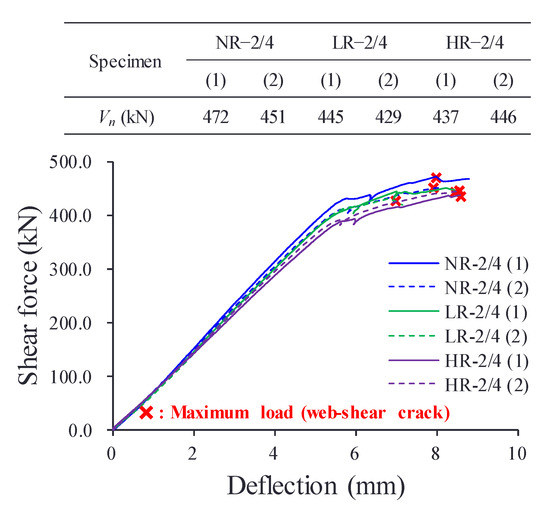
Figure 8.
Effect of helix shear reinforcement on shear strength.
3.2. Crack Patterns of PHCS Unit and Filled Core
Figure 9 shows the crack patterns that occurred in the PHCS unit and filled core. The crack patterns generated in the PHCS unit are indicated in red, while those in the filled core are indicated in blue, along with the shear crack angles. In general, the shear crack angles of reinforced concrete (RC) members range from 40° to 45°, while those of prestressed concrete (PSC) members range from about 30° to 38°, depending on the magnitude of the effective prestress [2,5,12]. The shear crack angles measured in the PHCS unit were found to range from 30° to 34°, which range is similar to that of the shear crack angle observed in general PSC members. On the other hand, the crack angles generated in the filled core were distributed in the range of 53° to 76°, well above 45°. In addition, it was confirmed that the cracks occurred along the interface between the filled cores and the PHCS unit, and this phenomenon was most clearly observed in the NR-4/4 specimen. These observations indicate that the PHCS unit and filled cores did not exhibit full composite behavior, and this means that there is a difference in the point of time for shear strength development of the filled cores and the PHCS unit.
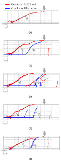
Figure 9.
Difference between crack patterns of the PHCS unit and filled core. (a) NR-0/4 specimen. (Inclined crack angle —30°). (b) NR-2/4 specimen. (Inclined crack angle—PHCS unit: 35°, filled core: 53°). (c) NR-4/4 specimen. (Inclined crack angle—PHCS unit: 34°, filled core: 76°) (d) LR-2/4 specimen. (Inclined crack angle—PHCS unit: 33°, filled core: 70°). (e) HR-2/4 specimen. (Inclined crack angle—PHCS unit: 34°, filled core: 65°).
Figure 10 shows strains measured from helix shear reinforcement placed in the LR-2/4 and HR-2/4 specimens. It is confirmed that the strains of the shear reinforcements did not increase until the failure loads of the specimens, which indicates that the helix shear reinforcement did not contribute to effective shear resistance. This is because the angles of the shear cracks in the filled cores were very steep.
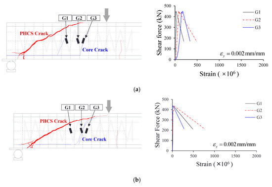
Figure 10.
Measured strain from shear reinforcement. (a) Measured strain from the LR-2/4 specimen. (b) Measured strain from the HR-2/4 specimen.
3.3. Discussions on the Web-Shear Strength of Prestressed hollow core slab (PHCS) Reinforced by the Core-Filling Method
The shear resistance mechanism of the PHCS with filled cores was analyzed based on the test results shown in Figure 6, Figure 7, Figure 8, Figure 9 and Figure 10. It is estimated that when a large shear force is applied to the member, a slip occurs at the interface between the PHCS unit and the filled cores, making them difficult to exhibit full composite behavior. As the slip increases, the shear stress transferred from the PHCS unit to the filled cores decreases, and thus the shear demand of the PHCS unit increases. Therefore, the PHCS unit reaches its potential shear capacity before the filled cores. In other words, it is considered that the filled cores partially contributed to the shear resistance of the member, but failed to reach 100% of its shear capacity, because the shear stress transmitted by the bond stress was insufficient due to the slip between the PHCS unit and filled cores. For this reason, the shear reinforcement also did not contribute to the shear resistance mechanism.
4. Review of the Code Provisions and Recommendation
The shear strength of the PHCS with filled cores can be obtained by estimating each of the shear contributions of the PHCS unit and filled cores and adding them. However, as mentioned earlier, it is very difficult to accurately estimate each of these shear contributions because of the slip and complex interactions between the PHCS unit and the filled cores. Nevertheless, since the core-filling method has been actively applied in the construction field for the shear strengthening of the PHCS, it is necessary to examine whether the shear strength of the PHCS with filled cores can be calculated using the current design codes. Therefore, in this study, the shear strengths of the specimens were evaluated using the shear strength equations for one-way RC and PSC members presented in ACI 318-14 [16], CSA-A23.3-14 [22], and BS EN1168 [23] codes, as shown in Table 1. Based on the evaluation results, this study aims to propose a modified equation that can properly reflect the shear strengthening effect of the core-filling method.
4.1. Considerations for Estimating the Web-Shear Strength of the PHCS with Filled Cores
The shear strengths of the specimens were calculated by summing up each of the shear strengths of the PHCS unit, filled cores, and shear reinforcement (, , and ). When the shear strengths were calculated using the ACI 318-14 code equation, it was assumed that the location of the critical section was away from the support, and the reduced effective prestress considering transfer length () was applied in estimating the compressive stress of concrete at the centroid of the section due to effective prestress (). In addition, since it is difficult to clearly define the effective depth () of the core when estimating the shear strength of the filled cores, the gross-sectional area of the filled cores () was used, instead of the shown in Table 1.
The CSA-A23.3-14 [22] code prescribes that for members whose yield strength of longitudinal reinforcement is not more than 400 MPa, and whose compressive strength of concrete does not exceed 60 MPa, the shear strength can be calculated using the simplified method, instead of the general method. Therefore, since the compressive strength of the filled cores () was 25.1 MPa, the shear strength of the filled cores was calculated using the simplified method, while that of the PHCS unit was estimated using the general method. In addition, the contribution of shear reinforcement () was also estimated, the 35° presented in the simplified method was applied as a shear crack angle (), and the location of the critical section was considered to be distance away from the support.
Unlike the ACI and CSA codes, the BS EN 1168 [23] code provides equations that are capable of estimating the shear strength of PHCS with filled cores. It also specifies that a web-shear strength equation presented in Eurocode2 is applied to calculate the shear strength of the PHCS unit, and that the shear strength of the filled cores is calculated by multiplying the tensile strength of concrete () by the sectional area of core (). Eurocode2 [26] stipulates that material coefficients are applied to ensure the safety margin of structural members. In this study, all material coefficients were assumed to be 1.0, since the purpose of this study is to evaluate the accuracy of the code equations. However, if the material coefficient is not taken into account in the tensile strength of concrete () included in the equation for estimating transfer length presented in Eurocode2, the shear strength of the PHCS unit would be overestimated due to the transfer length which is calculated to be excessively small. Therefore, a concrete material coefficient of 1.5 was applied in the calculation of the transfer length.
4.2. Comparison of Shear Strengths by Testing and the Code Equations
Table 5 compares the shear strengths of the test specimens () and those calculated using the design codes (). The ACI 318-14 code provided conservative evaluations of shear strengths for specimens other than the HR 2/4 specimen due to the additional strength reduction factor (0.5) provision applied to PHCS with thickness greater than 315 mm. When the additional strength reduction factor was not applied, as in the ACI 318-05 provision, the ACI code equation evaluated the shear strengths of the NR-0/4 and NR-2/4 specimens very accurately, while it showed a tendency to considerably overestimate the shear strengths of the NR-4/4, LR-2/4, and HR-2/4 specimens.

Table 5.
Comparison of test and calculation results.
The CSA-A23.3 code provided conservative evaluations on the shear strengths of the NR-0/4 and NR-2/4 specimens, and estimated the shear strengths of the remaining specimens to be on the unsafe side. The BS EN 1168 code also provided the shear strength estimation results on the unsafe side for all specimens. In particular, all structural design codes, except for ACI 318-14, provided the shear strength estimation results on the unsafe side with respect to the NR-4/4 specimen in which all hollow cores were strengthened by in-filled concrete, and LR-2/4 and HR-2/4 specimens with helix shear reinforcements. As can be identified from the test results reported earlier, the reasons are that the increase in shear strength was clearly observed in the NR-2/4 specimen with two filled cores compared to the NR-0/4 specimen, whereas that measured in the NR-4/4 specimen with four filled cores was smaller than the NR-2/4 specimen, because the web of the PHCS unit at the edge of the section was separated from the filled core before reaching the ultimate load. A further reason is that the helix shear reinforcement placed in the filled cores failed to exert effective shear resistance. Therefore, a close examination of the code equations is needed to estimate the shear strengths of PHCS with filled cores safely and accurately using the design codes.
4.3. Modified Shear Strength Equation for the PHCS with Filled Cores
For shear strengthening of the PHCS, the top flange of the PHCS unit should be cut lengthwise and opened to fill the hollow cores with concrete. The test results showed that when the entire hollow core is filled with concrete, the interface between the web of the PHCS unit at the edge of the section and the filled core is damaged, as shown in the upper right corner of Figure 11a, which makes it difficult to provide effective shear resistance to the external shear force. Therefore, in this study, the section of the PHCS with filled cores was idealized, as shown in the lower right corner of Figure 11a, and only the part corresponding to the area marked with oblique lines was assumed to exert effective shear resistance. In addition, the contribution of shear reinforcement () was ignored because the helix reinforcement placed in the filled cores did not contribute to shear resistance mechanism.
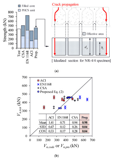
Figure 11.
Proposed method for estimating shear strength of PHCS with filled cores. (a) Estimation of shear strength of PHCS with four filled cores. (b) Comparison of test and calculation results.
As shown in Table 1 and Table 5, the shear strength equation presented in the ACI 318-14 code has a simple form, but was found to provide very approximate predictions of the shear strengths of the NR-0/4 and NR-2/4 specimens when the additional shear reduction factor (0.5) was not taken into account. Therefore, this study modifies the shear strength equation of ACI 318 to fit the PHCS with filled cores, as follows:
where, is the ratio of the number of filled cores to the number of entire hollow cores (), and are the concrete compressive strength of filled core and the PHCS unit, respectively, is the compressive stress of concrete at the centroid of the section due to effective prestress, and are the width and height of filled cores, respectively, is the web width of the PHCS unit, and is the depth of the prestressing strand. In addition, when is less than 1.0, is taken at 1.0; while if is 1.0, it is calculated at . As shown in Table 6 and Figure 11b, the proposed Equation (2) provided very accurate evaluations on the shear strengths of all the specimens, regardless of the number of filled cores (i.e., the average and the coefficient of variance (COV) of were 0.98 and 0.04, respectively). However, it should again be noted that when the PHCS is utilized in the actual construction field, the members are continuously placed, and cast-in-place concrete or non-shrink mortar is poured between the members, which may delay the separation of the PHCS unit web from the filled cores. In this regard, there is a need to conduct additional experimental research.

Table 6.
Verification results of proposed equation.
5. Conclusions
In this study, experimental research was performed to investigate the shear resistance mechanism of the PHCS strengthened by the core-filling method. The number of filled cores and the shear reinforcement ratio were set as test variables, and the behavior of the specimens, as well as the patterns and angles of cracks that occurred in the PHCS units and filled cores, were analyzed in detail. In addition, this study examined whether the shear strength equations specified in the ACI 318-14, CSA-A23.3-14, and BS EN1168 codes provide reasonable evaluations of the shear strengths of the PHCS with filled cores, and proposed a modified equation that is capable of properly reflecting the shear strengthening effects of the core-filling method. Based on the findings of this study, the following conclusions can be drawn:
- The NR-2/4 specimen which has two hollow cores filled with normal strength concrete, showed a 32%–38% increase in shear strength compared to the NR-0/4 specimen, while the shear strength of the NR-4/4 specimen with four hollow cores strengthened increased by only 24%–25%, compared to that of the NR-0/4 specimen. This is because the web of the PHCS unit at the edge of the NR-4/4 specimen was separated from the filled core before reaching the ultimate load, and thus the edge web failed to exert effective shear resistance.
- The shear crack angle of the PHCS unit ranged from 30° to 34°, whereas a very steep crack angle ranging from 53° to 76° occurred in the filled core. In addition, cracks were observed along the interface between the PHCS unit and the filled cores, resulting in the slip between the PHCS unit and the filled cores, which in turn led to a failure of full composite behavior. As a result, the filled core made a partial contribution to the shear resistance of the member, but did not exert its shear capacity due to the slip between the PHCS unit and the filled cores.
- The shear strengths of the LR-2/4 and HR-2/4 specimens strengthened with helix reinforcing bars were almost similar to the shear strength of the NR-2/4 specimen without shear reinforcement. In other words, the shear reinforcement did not exert a proper shear resistance, which is because the shear crack did not cross the helix reinforcing bars.
- The ACI 318-14 code provided conservative evaluations of the shear strengths of the specimens, while the CSA-A23.3 code tended to estimate the shear strengths of the NR-4/4, LR-2/4, and HR-2/4 specimens to be on the unsafe side. In particular, the BS EN 1168 code provided shear strength estimation results on the unsafe side for all of the specimens.
- The separation of the web of the PHCS units and the filled cores at the edge of the section should be considered when applying the code equations, in order to avoid unsafe shear design of the PHCSs reinforced by the core-filling method.
- To understand the shear transfer mechanism of the PHCS units and core-filling concrete more clearly, further research is still needed: (1) Push-off tests of PHCS with filled cores to obtain the bond properties between PHCS and core-filling concrete; (2) Finite element analysis considering the bond–slip relationship; (3) Shear tests of PHCS with core-filling and topping concrete.
Author Contributions
Original draft manuscript, H.-E.J.; validation, S.-J.H.; investigation, M.-K.P.; supervision and review writing, K.S.K. All authors have read and agreed to the published version of the manuscript.
Funding
This work was supported by the National Research Foundation of Korea (NRF) grant funded by the Korea Government (MSIT) (No. 2019R1A2C2086388).
Conflicts of Interest
The authors declare no conflict of interest.
References
- Kankeri, P.; Prakash, S. Efficient hybrid strengthening for precast hollow core slabs at low and high shear span to depth ratios. Compos. Struct. 2017, 170, 202–214. [Google Scholar] [CrossRef]
- Celal, M.S. Behaviour of Precast/Prestressed Hollow-Core Slabs. Master’s Thesis, University of Manitoba, Manitoba, Canada, 2011. [Google Scholar]
- El-Arab, I.M.E. Web Shear Strengthening Technique of Deep Precast Prestressed Hollow Core Slabs under Truck Loads. J. Bldg. Constr. Plan. Res. 2017, 5, 129–145. [Google Scholar] [CrossRef]
- Wu, Y.; Cheng, S.; El-Ragaby, A.; Mehta, A. Effectiveness of a Novel Technique in Strengthening Web-Shear Capacity of Prestressed Hollow Core Slabs Using Externally Bonded FRP Sheets. J. Compos. Constr. 2017, 21, 1–14. [Google Scholar] [CrossRef]
- Lee, D.H.; Park, M.K.; Oh, J.Y.; Kim, K.S.; Im, J.H.; Seo, S.Y. Web-Shear Capacity of Prestressed Hollow-Core Slab Unit with Consideration on the Minimum Shear Reinforcement Requirement. Comput. Concr. 2014, 14, 211–231. [Google Scholar] [CrossRef]
- Park, M.K.; Lee, D.H.; Han, S.J.; Kim, K.S. Web-Shear Capacity of Thick Precast Prestressed Hollow-Core Slab Units Produced by Extrusion Method. Int. J. Concr. Struct. Mater. 2019, 13, 1–14. [Google Scholar] [CrossRef]
- Becker, R.J.; Buettner, D.R. Shear Tests of Extruded Hollow-Core Units. PCI J. 1985, 30, 40–54. [Google Scholar] [CrossRef]
- Im, J.H.; Park, M.K.; Lee, D.H.; Kim, K.S.; Seo, S.Y. Evaluation of web-shear capacity of thick hollow-core slabs. Reg. Assoc. Archit. Inst. Korea 2014, 16, 139–145. (In Korean) [Google Scholar]
- Tawadrous, R.; Morcous, G. Shear Strength of Deep Hollow-Core Slabs. ACI Struct. J. 2018, 115, 669–709. [Google Scholar] [CrossRef]
- Brunesi, E.; Bolognini, D.; Nascimbene, R. Evaluation of the shear capacity of precast-prestressed hollow core slabs: Numerical and experimental comparisons. Mater. Struct. 2015, 48, 1503–1521. [Google Scholar] [CrossRef]
- Palmer, K.D.; Schultz, A.E. Factors affecting web-shear capacity of deep hollow-core. PCI J. 2010, 55, 123–146. [Google Scholar] [CrossRef]
- Palmer, K.D.; Schultz, A.E. Experimental investigation of the web-shear strength of deep hollow-core units. PCI J. 2011, 56, 83–104. [Google Scholar] [CrossRef]
- Hawkins, N.M.; Ghosh, S.K. Shear Strength of Hollow-Core Slabs. PCI J. 2006, 51, 110–115. [Google Scholar]
- El-Sayed, A.K.; Al-Negheimish, A.I.; Alhozaimy, A.M. Web Shear Resistance of Prestressed Precast Deep Hollow Core Slabs. ACI Struct. J. 2019, 116, 139–150. [Google Scholar] [CrossRef]
- ACI Committee 318-08. Building Code Requirements for Structural Concrete and Commentary (ACI 318R-08); American Concrete Institute: Farmington Hills, MI, USA, 2008. [Google Scholar]
- ACI Committee 318-14. Building Code Requirements for Structural Concrete and Commentary (ACI 318R-14); American Concrete Institute: Farmington Hills, MI, USA, 2014. [Google Scholar]
- Brunesi, E.; Nascimbene, R. Numerical web-shear strength assessment of precast prestressed hollow core slab units. Eng. Struct. 2015, 102, 13–30. [Google Scholar] [CrossRef]
- Girhammar, U.A.; Pajari, M. Tests and analysis on shear strength of composite slabs of hollow core units and concrete topping. Constr. Build. Mater. 2008, 22, 1708–1722. [Google Scholar] [CrossRef]
- Nguyen, T.N.H.; Tan, K.H.; Kanda, T. Investigations on web-shear behavior of deep precast, prestressed concrete hollow core slabs. Eng. Struct. 2019, 183, 579–593. [Google Scholar] [CrossRef]
- University of Seoul; Korea National University of Transportation; Yunwoo Structural Engineering. Prestressed Hollow-Core Slabs; Samsung C&T Research Report; University of Seoul: Seoul, Korea, 2012. [Google Scholar]
- Lee, D.H.; Park, M.K.; Joo, H.E.; Han, S.J.; Kim, K.S. Strengths of Thick Prestressed Precast Hollow-Core Slab Members Strengthened in Shear. ACI Struct. J. 2020, 117, 1–12. [Google Scholar] [CrossRef]
- CSA A23.3-14. Design of Concrete Structures; Canadian Standards Association: Mississauga, ON, CA, 2014. [Google Scholar]
- EN 1168. Precast Concrete Products−Hollow Core Slabs; European Committee for Standardization: Brussels, Belgium, 2005. [Google Scholar]
- ACI Committee 318-05. Building Code Requirements for Structural Concrete and Commentary (ACI 318R-05); American Concrete Institute: Farmington Hills, MI, USA, 2005. [Google Scholar]
- Hegger, J.; Roggendorf, T.; Kerkeni, N. Shear capacity of prestressed hollow core slabs in slim floor constructions. Eng. Struct. 2009, 31, 551–559. [Google Scholar] [CrossRef]
- EN 1992-1-1. Design of Concrete Structures—Part 1-1: General Rules and Rules for Buildings (Eurocode 2); European Committee for Standardization: Brussels, Belgium, 2004. [Google Scholar]
- Yang, L. Design of Prestressed Hollow-Core Slabs with Reference to Web Shear Failure. J. Struct. Eng. 1994, 120, 2675–2696. [Google Scholar] [CrossRef]
© 2020 by the authors. Licensee MDPI, Basel, Switzerland. This article is an open access article distributed under the terms and conditions of the Creative Commons Attribution (CC BY) license (http://creativecommons.org/licenses/by/4.0/).