Abstract
In a shipyard, large numbers of temporary pieces are used to align welding lines of a block joint and prevent welding deformations in the block assembly stage. The use of many temporary pieces requires a great number of working man-hours, causing low productivity. In this study, experiments and numerical analyses of welding deformations were carried out in order to optimize the number of temporary pieces used. The quantitative relationship between the welding deformations and the temporary piece setting was established experimentally. In order to predict welding deformations considering temporary piece setting, a numerical method was proposed. The simulation results were verified through experiments. The optimal number of twenty-one temporary pieces needed to increase the productivity was calculated with the proposed numerical analysis method. Moreover, the proposed numerical analysis method could be used to establish guidelines and plans for a proper use of temporary pieces on the panel block assembly stage.
1. Introduction
While carrying out welding work on the hull block joint, a plate jig, referred to as temporary piece, is generally used to correct misalignment and prevent welding deformation [1]. However, because the deformations cannot be prevented and the weight increases if pieces become larger than a specific size, each shipyard uses a standardized piece, with specific shape and size. Figure 1 shows the working area of a temporary piece in the block assembly stage, Figure 2 shows the working area in the block erection stage, and Figure 3 presents technical drawings for representative standardized temporary pieces and strong-back. In each shipyard, some hundred thousand temporary pieces are used in a year, according to its scale, and the production time required for piece installation, removal, grinding, and work completion also mounts to some hundred thousand hours. A survey found that around 38,000 temporary pieces are used for only one unit of a 50,000 deadweight tonnage (DWT) tanker [2]. Furthermore, quality accuracy control of the hull block, by controlling deformations caused by welding, is very important for improving the productivity in the assembly and erection stages. Therefore, reduced usage of temporary piece, while maintaining a welding quality of hull block, is required.
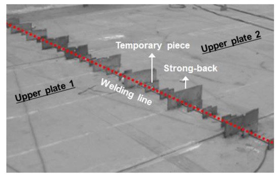
Figure 1.
Temporary pieces set up for welding at block assembly stage.
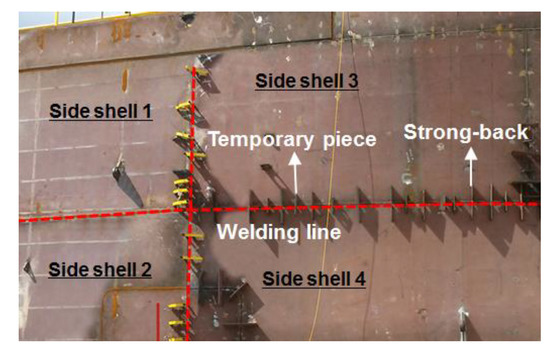
Figure 2.
Temporary pieces set up for welding at block erection stage.
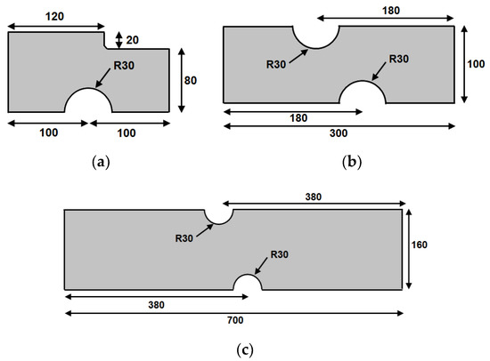
Figure 3.
Design of the pieces and strong-backs used in the experiments: (a) temporary piece (LA-4); (b) strong-back (S-3); and (c) strong-back (S-4).
Interest in the optimization of butt joint welding has generated many analytical and experimental studies [3,4,5,6]. Furthermore, the studies have been made to reduce residual stresses and deformations of fillet weld joints. Perić et al. carried out a numerical simulation for reducing longitudinal residual stress and deformation using a local preheating technique [7]. The authors analyzed the correlation between residual stress and deformation according to preheating temperature and inter-pass time. Recently, efforts to precisely evaluate the residual stress and deformation of the butt-welded joint have been aided by finite element analysis, thanks to the development of increasingly more powerful computers. However, most of the research done has been limited to a range of simple welded joint model levels [8,9]. Finite element simulations of the welding deformation of large structures, such as aircraft fuselages and hull blocks, have the downside of generating a quite large deviation from the real welding deformations in spite of large calculation times, due to considering the nonlinearity of materials [10]. It is known that the accuracy of the simulation result is largely relying on an appropriate consideration of the weld area affected by heat [11,12,13]. Hernando et al. explained a laser beam welding (LBW) model to predict the geometry of the resulting joint when welding thin Inconel 718 plates used in the aerospace industry [14]. Jang et al. and Park et al. carried out simulations of the welding deformation by the assembly sequence of reinforced plate of hull body, by combining the equivalent load method and finite element method based on the inherent strain [15,16]. Kim et al. proposed an equivalent strain method, based on inherent strain for curved double bottom ship block [17]. Kang et al. modified the inherent strain method to include the friction stir welding process [18]. This method expedited calculation time by simplifying a complicated thermal elasto-plastic analysis by using the inherent strain theory. However, this method has limitations in deciding the size and distribution area of inherent deformations. Furthermore, it requires an inconvenient process of obtaining a degree of restraint, each time, if external restraint condition is changed. Meanwhile, several studies have focused on the welding deformation itself. Deng et al. clarified the generation mechanism of angular distortion in fillet welded joints through numerical simulations and experiments [19]. Adamczuk et al. developed a methodology to predict the angular distortion in multipass V-butt joint welding based on experimental and analysis results [20]. They analyzed the behavior of angular distortion along the passes performed. Mochizuki and Okano investigated the effect of the welding process and heat input conditions on the angular distortion induced by bead-on-plate welding through a numerical approach [21]. They developed the parameter of mechanical melting region on the plate thickness and found that it was the dominant factor for accurately quantifying angular distortions. Xie et al. revealed the mechanism of angular distortion in fusion welding and how the welding processes and factors influence the angular distortion [22]. They established a theoretical model concerning the melting–solidification process and formulated an expression for angular distortion. Seong developed a systematic method to predict angular distortion in multilayer welding [23]. He defined the relationship between heat input, bead cross-section, angular distortion, and thickness through the bead-on-plate welding experiment and constructed databases from them. Then he proposed a method of predicting angular distortion in multilayer welding and verified it through welding experiments on V-groove butt joints. Ryu and Kim et al. conducted studies on the butt-welding deformation using pieces [24,25]. Ryu only conducted experimental studies on the butt welding deformation at the level of unit specimens. Kim et al. simulated the butt-welding deformation of hull block joints, however they did not derive the optimal number of pieces and neither they simulate the butt-welding deformation of large hull blocks.
In this study, a thermal elasto-plastic analysis based on the finite element method was employed to examine the welding deformation. The necessary parameters were chosen based on the experimental results, to guarantee the accuracy of the results. This study was carried out with the objective of maintaining quality accuracy of hull block and reducing temporary piece usage. The restraint effect of the temporary piece on the deformation of base plates during joint welding was reviewed both qualitatively and quantitatively through a series of butt-welding experiments. The calculation and analysis results were compared and verified with the experimental data. Lastly, the welding deformation on the hull block joint, considering the temporary piece, was simulated by using a verified analysis method, and the results obtained were compared with the experimental results. Based on these results and by placing the temporary pieces at the right places, an attempt to achieve quality accuracy of the butt joint welding area in panel block and saving the temporary piece usage at the same time was made.
2. Welding Deformation Experiments of Unit Specimen
Butt welding experiments were conducted on each different three welding test specimens, as shown in Figure 4, to compare the deformation by the number of pieces installed in the butt welding. Flux cored arc welding was employed as a welding method. The welding was carried out manually and performed using a welding machine (HD-auto 350s+) by Hyundai Welding Machine Company. Details of operation conditions are displayed in Table 1. The root gap and groove angle are defined as shown in Figure 5. The conditions employed during welding, other than the quantity of temporary pieces, are the same in all experiments.
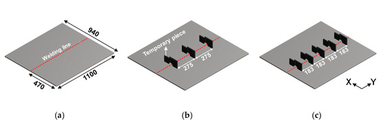
Figure 4.
Welding test specimens for three experimental cases: (a) specimen 1; (b) specimen 2; and (c) specimen 3.

Table 1.
Operation conditions of butt welding.
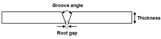
Figure 5.
Definition of root gap and groove angle.
Each specimen is of dimension 940 × 1100 × 15 mm. The base material is low carbon steel AH32, which is mainly used for hull blocks, and the filler material is E81T1-K2C wire type, conforming to the specification of the American Welding Society [26]. However, the thickness of the pieces is 12 mm and they are of the same material composition as the specimens. The three experimental cases analyzed, denoted specimen 1, 2, and 3, and each having a particular number of pieces installed (0, 3, and 5, respectively), are shown in Figure 4. Specimen 1 is a reference for measuring the welding deformation value when no piece is installed, which will be used for comparison with the welding deformation value when pieces are installed. For specimen 2, three pieces were installed at equal distance intervals of 275 mm. This distance is the average value of 250 and 300 mm, which is the piece installation interval empirically used in the workspace. In specimen 3, the welding deformation value is measured for five pieces installed at equal intervals of approximately 183 mm.
The specimen was fixed by tack welding at both ends of the welding line, and edges of the specimen were not constrained in order to observe the maximum deformation. The welding deformation value was measured by obtaining three-dimensional coordinate of marking points using a three-dimensional contact measuring instrument. The measuring instrument is the Metronor SOLO model with a ±0.21 mm accuracy in a 10 m distance camera; it was suitable for measuring deformations of large structures [27]. Marking points were made at 50 mm intervals on the opposite side of the piece mounting face and more closely to the welding bead, at 20 mm intervals, in grid form. The butt welding experiment was conducted for each case in the following order: butt joint welding, piece removal, grinding, and deformation measurement, as shown in Figure 6. The number of measuring points is 504. Figure 7 presents each measuring line position in the transverse direction, x1 to x5, and longitudinal direction, y1 to y3 (y1′ to y3′). Figure 8 illustrates the welding deformation measured along line x3 for each specimen. Because all three specimens had the same welded thickness, welding passes, and constraint conditions, the angular deformations shown in Figure 8 are the result of the difference in the number of installed pieces.
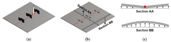
Figure 6.
Sequence of procedures per experiments: (a) Flux cored arc welding; (b) piece removal; and (c) measurement.
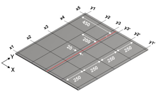
Figure 7.
Vertical and horizontal gridlines for welding deformation comparison.
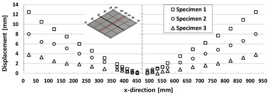
Figure 8.
Experimental results of horizontal welding deformations (line x3).
For the comparison of welding deformation, the measuring lines were set as shown in Figure 7. The maximum displacement for each case, against the measuring line of transverse (x) and longitudinal (y) directions, is shown in Table 2 and Table 3. The maximum displacements along the x-axes were measured using the basis z = 0 at the welding line (x = 475 mm). Those along the y-axes were measured using the basis z = 0 at both endpoints of each y-axes.
Table 2.
Experimental results of maximum displacements in x-direction [mm].
Table 3.
Experimental results of maximum displacements in y-direction [mm].
As the installed number of pieces was increased, that is, as the installation gap between piece was decreased, the welding angular deformation was reduced by a remarkable difference, as shown in Table 2. Compared to the case without pieces (specimen 1), based on the average value for each specimen, the deformation is reduced by 38% when installing three pieces and by 74% when installing five pieces. Specimen 1 shows that the angular deformations of the welding start line (x1) and the end line (x5) relatively increase, due to the edge effect. However, specimens 2 and 3 show different deformation distributions than specimen 1, due to the piece restraint effect.
In case of longitudinal bending deformation, presented in Table 3, specimen 2 is showing 32% reduction and specimen 3, 43%, with respect to specimen 1, which conveys that installing pieces is effective in reducing this type of deformation. These numbers are smaller than the values of the corresponding angular deformation reduction, which means that the pieces installation has the effect of reducing mainly the welding angular deformation. In addition, the difference in longitudinal bending deformation value between specimen 2 and specimen 3 is small when compared to the difference in angular deformation. The butt welding experiment, as described above, yielded qualitative as well as quantitative data for the prevention of welding deformation by installing pieces. These experimental results will be utilized for comparison and verification, to establish the reliability of the deformation analysis method and simulations.
3. Welding Deformation Analysis of Unit Specimen
Based on the results of the butt-welding experiment involving pieces, we aim to establish a method of butt welding thermal elasto-plastic analysis. For this purpose, analysis tools such as welding heat input model and boundary condition were selected through the following process:
- (1)
- Butt welding thermal elasto-plastic analysis was performed using a commercial finite element analysis program (MSC MARC).
- (2)
- A 4-node bilinear shell was used for heat transfer analysis, and nine integration points were set to represent linear temperature gradients in the thickness direction, improving the calculation time efficiency of this model in comparison to the solid element analysis. The proposed shell element calculates the temperature distribution by bilinear interpolation in the plane direction. In the thickness direction, temperature gradients are represented by Simpson’s rule with up to 11 integral points, assuming linear or quadratic temperature distribution.
- (3)
- A moving heat source was used to simulate three-dimensional effects, such as longitudinal bending deformation and edge effects. To apply the moving heat source to the analysis, the weld beads were generated with the welding speed using the activate elements technique [28].
- (4)
- The left-right symmetry model was created based on the welding line, and the boundary conditions to prevent rigid motions were applied to the temporary tack welding area for the specimens fixed together with the symmetry boundary conditions.
- (5)
- Temperature-dependent material properties [4] were used for extracting the values for Young’s modulus, yield stress, specific heat, conductivity, and thermal expansion coefficient. The temperature-dependent material properties, including tangent modulus, which characterizes the plastic properties of the material, are summarized in Figure 9.
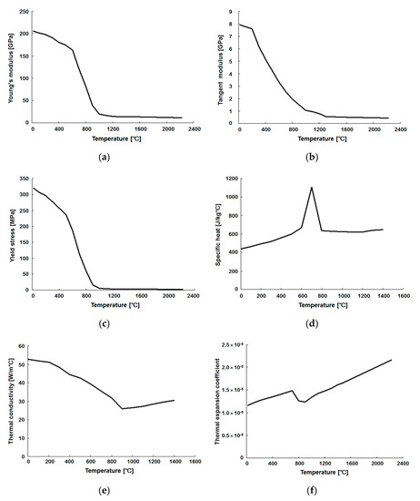 Figure 9. Temperature-dependent material properties: (a) Young’s modulus; (b) tangent modulus; (c) yield stress; (d) specific heat; (e) conductivity; and (f) thermal expansion coefficient.
 - (6)
- In general, for manual arc welding, the welding speed, current, and voltage are irregular and influenced by the skill of the operator and the surrounding environment. In this study, a relatively stable manual welding was obtained by monitored and repeated preliminary experiments, so that the welding speed, current, and voltage could be kept within the range of field construction guidelines from Table 1. The welding conditions used in the analysis utilized an average value of these ranges, increasing the analytical time efficiency by reducing the number of steps in the analysis instead of using changes of the weld conditions over time, occurring in the actual welding experiment. The analysis welding conditions used are welding speed of 150 mm/min, welding current of 240 A, and arc voltage of 29 V.
- (7)
- Based on the experimental results of specimen 1, the similarity between simulated and experimental results was calculated while changing the values of the analysis variables, which is shown in Table 4. The heat flux radius of 135 mm, R135, the analysis parameter value for the highest similarity, was determined as the analysis condition. The heat flux parameter refers to the radius of the disc heat flux model [3] used in this analysis. The disc-shaped heat flux model can be expressed by the function presented in Equation (1),
Table 4. Agreement test for experimental and analysis results (specimen 1).
Figure 10 and Figure 11 show an example, comparing the analysis results of angular and longitudinal bending deformation according to the analysis variable values and the experimental data of specimen 1. The analysis result of R135 is very similar to that of specimen 1.
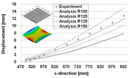
Figure 10.
Angular bending deformation results by heat flux radius (x1).
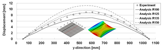
Figure 11.
Longitudinal bending deformation results by heat flux radius (y2).
Next, we verified the validity of the welding deformation analysis method considering piece models based on the experimental results of specimen 1. The analytical models for specimen 2 and specimen 3 are shown in Figure 12. Butt welding deformation analysis was performed by applying the same welding deformation analysis conditions as in specimen 1.
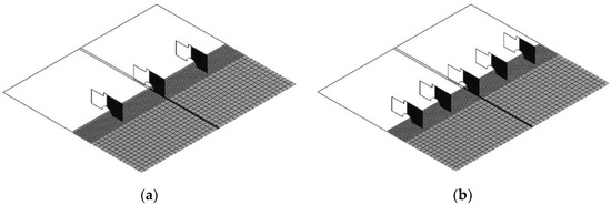
Figure 12.
Symmetric finite element models including piece elements: (a) specimen 2 and (b) specimen 3.
Figure 13 and Figure 14 show the angular deformation (x4) and the longitudinal bending deformation (y2) for each case, describing similar trends in other comparison lines. As presented in Figure 13, angular deformation (x4) is relatively well matched with experimental results, but the longitudinal deformation (y2) of Figure 14 is slightly different in specimen 3. However, considering that the experimental results of specimen 3 are relatively small, the proposed analytical method can simulate well an experimental phenomenon.
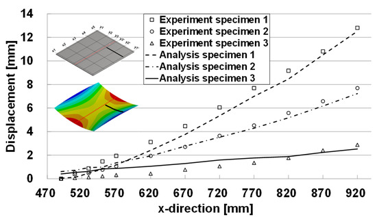
Figure 13.
Butt welding analysis and experimental results (line x4).
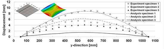
Figure 14.
Butt welding analysis and experimental results (line y2).
4. Welding Deformation Experiment and Analysis of Panel Block Assembly
Based on the butt-welding deformation analysis method described in Section 3, we performed the joint welding deformation analysis for the panel block and then verified the results. As shown in Figure 15, the joint welding deformation of a panel block model was measured using a three-dimensional contact measuring instrument. The joint welding deformation analysis was performed for the block with the pieces installed, and the results were compared in order to verify the panel block joint welding deformation analysis method.
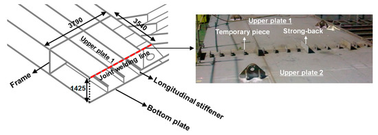
Figure 15.
Panel block model for method validation.
Figure 16 shows the finite element analysis model generated by joint welding area of the panel block illustrated in Figure 15. The idealized panel block’s finite element model is equipped with 4 strong-backs and 13 temporary pieces. The model is divided into six longitudinal stiffeners and two frames, and five reinforcement frames are provided on the inclined plate.
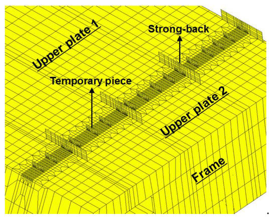
Figure 16.
Finite elements model of panel block.
Figure 17a schematically shows the positions of the pieces installed on the actual panel block. The position and average spacing of each piece are shown in Table 5. Figure 17b is another simulation model in which the number of pieces installed is reduced by increasing the piece average installation distance from 221 mm to 376 mm. As shown in Table 6, the four strong-backs are kept at the same position, as shown in Figure 17a, and only six pieces are installed, two of them at equal intervals between each of the strong-backs. The welding deformation analysis for this configuration was performed to verify the welding deformation results when the number of piece installations was decreased.
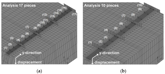
Figure 17.
Pieces’ positions on panel block: (a) details of 17 pieces and (b) details of 10 pieces.
Table 5.
Positions of 17 pieces on panel block (a).
Table 6.
Positions of 10 pieces on panel block (b).
Figure 18 shows the results of the welding deformation analysis for the panel block with pieces installed, curves analysis 1 and analysis 2, and without pieces, analysis 3. Additionally, Figure 18 shows the experimentally acquired data for the panel block installed 17 pieces. The numerical analysis results, analysis 1, and the corresponding measured values, experiment, were qualitatively similar along most of the displacement axis (y-direction in Figure 18). The quantitatively different portions could be caused by a combination of the limited number of measuring points and inherent measurement errors. On the other hand, reducing the total number of pieces from 17 to 10 yields similar deformation analysis results, except at the free edge of the displacement axis (y = 3500 mm~3790 mm). This shows a real possibility of cutting costs and welding time by reducing the number of pieces used currently. However, when no piece is installed, the welding deformation greatly increases at the free edge as well as among longitudinal stiffeners (y = 2000 mm). Therefore, it is clear that the piece installation has, indeed, the effect of preventing welding deformation.
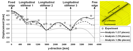
Figure 18.
Experimental and analysis results of joint welding deformations for panel block.
5. Application of Calculating the Appropriate Temporary Piece Usage
In order to investigate the proper temporary piece installation in the block assembly stage, a panel block model in the bottom area of the 81,000 DWT bulk carrier was selected as shown in Figure 19.
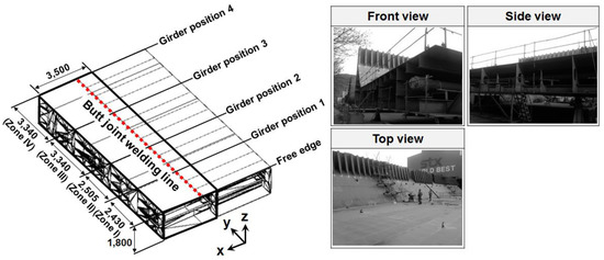
Figure 19.
Panel block for simulation.
The panel block finite element model was created, as shown in Figure 20, to examine the joint welding line in the hull width direction. The model is divided into two frames in the bow direction and four girders in the hull width direction, based on the joint welding line. The finite element model consists of a frame, girder, upper plate, bottom plate, and 20 longitudinal stiffeners. A strong-back and a temporary piece are also included. The distance between the strong-back and the temporary piece was applied through the field survey. There are 5 strong-backs and 39 pieces in the finite element model.
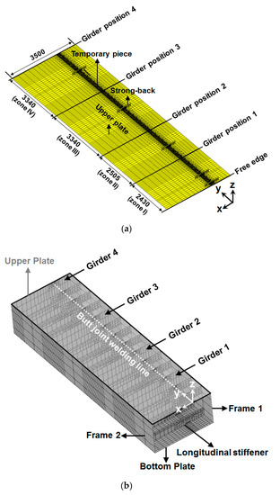
Figure 20.
Finite elements model of panel block: (a) upper plate and pieces and (b) whole model.
The welding deformation analysis was performed with the purpose of identifying the deformation pattern of panel block joint welding according to the number of pieces and calculating the number of proper piece installations. Welding deformations were calculated for 39 pieces (simulation 1, current), 19 pieces (simulation 2), and 0 pieces (simulation 3). Figure 21 shows the final deformation for the simulation 1 upper plate. In the region between girders, displacement occurred in the direction opposite to the surface where the piece was installed.
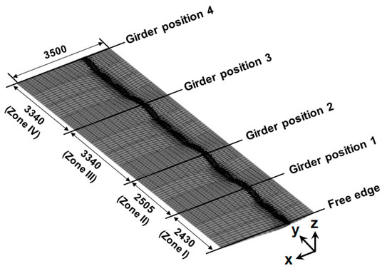
Figure 21.
Deformed shape of upper plate (simulation 1).
Figure 22 shows the comparison of the displacements in the welding direction for each simulation. In all simulations, deformation rarely occurs in the girder region, and a relatively small difference of displacement occurs between longitudinal stiffeners in simulation 1 and simulation 2.
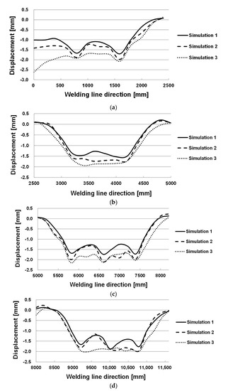
Figure 22.
Simulation results (displacement in welding line direction x = 0 mm): (a) zone I; (b) zone II; (c) zone III; and (d) zone IV.
As an example of calculated results, Figure 23 shows the angular deformation at y = 6600, for all three simulations. It can be seen that angular deformations are distributed along y-direction with each maximum displacement, as shown in Figure 22.
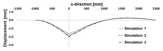
Figure 23.
Simulation results (displacement in x-direction y = 6600 mm).
In this study, the number of proper piece installations was calculated as follows, referring to the simulation result of Figure 22. First, the curve of the deformation result without using pieces (simulation 3) was set as the deformation limit. The appropriate number of pieces necessary to satisfy the deformation limit and to approach the current deformation curve (simulation 1) was determined. The result obtained when using 19 pieces (simulation 2) shows that, in this case, the deformation limit is not satisfied between the two longitudinal stiffeners regions (6600 mm < y < 7400 mm, 10,000 mm < y < 10,800 mm), as seen in Figure 22c,d. In other words, additional pieces are installed in these two areas. Therefore, in the case of the panel block model, a total of twenty-one pieces was determined to be the number of piece installations. Compared to the currently used number (simulation 1), a piece usage reduction of 46% can be expected. Additionally, in terms of weight reduction, the piece weight of approximately 34 kg could be reduced; moreover, the piece installation and removal time of approximately 450 min is expected to be reduced. Because a reduction in the number of pieces leads to a reduction of the external constraint force acting on the base plates, it is necessary that the welding residual stress decreases by a certain amount in both tension and compression.
6. Conclusions
This study was conducted with the objectives of maintaining quality accuracy of the panel block on the assembly stage and providing a detail plan of temporary piece installation during joint welding of the panel block. The major results obtained are as follows:
- (1)
- The butt-welding experiments carried out to determine the temporary piece installation number impact on welding distortions demonstrated that the angular distortion and longitudinal bending deformation decreased when the piece installation number increased.
- (2)
- The deformation calculation method for butt joint welding with temporary pieces attached was developed using the thermal elasto-plastic finite element analysis. The comparison between the experimental and analysis results confirmed that the proposed analysis method is sufficiently suitable to simulate the butt-welding deformation considering the installation of pieces.
- (3)
- In order to apply the proposed method to large scale blocks with temporary pieces installed, welding deformations of the panel block were measured, and butt-welding deformation analysis was performed by generating the finite element model of the same panel block. The measurement and analysis results show good agreement in both qualitative and quantitative terms.
- (4)
- By calculating the proper number of temporary pieces installed, the possibility of reducing the welding time and number of pieces currently used was examined by welding deformation analysis. The results indicate that, for large panel blocks, the temporary piece usage can be theoretically reduced by up to 46%. However, in a shipyard setting a lower reduction percentage is expected, because the calculations do not reflect unexpected field conditions, such as the initial deformation of the weld joint line in the piece assembly or the effect of the pieces installed to adjust the misalignment.
- (5)
- The proposed analysis method is expected to be useful in a variety of fields as an analysis tool for planning the salvage of temporary pieces, through the preparation of piece deployment drawings and installation guides at a preliminary stage.
Author Contributions
Conceptualization, H.R. and K.L.; methodology, H.R. and K.L.; software, H.R. and S.K.; validation, H.S. and S.K.; formal analysis, H.R. and S.K.; investigation, H.R. and K.L.; resources, H.R. and K.L.; data curation, S.K.; writing—original draft preparation, H.R and K.L.; writing—review and editing, S.K. and K.L.; visualization, S.K.; supervision, H.R.; project administration, H.R.; funding acquisition, H.R. All authors have read and agreed to the published version of the manuscript.
Funding
This research received no external funding.
Conflicts of Interest
The authors declare no conflict of interest.
References
- Park, J.U. Prevention and Correction of Welding Deformation. J. Korean Weld. Soc. 2005, 23, 12–16. [Google Scholar]
- Noh, H.Y.; Kim, K.J.; Leem, R.S.; Kim, H.K. A Study on a Development of the Grinding Robot to Remove Welding-bid of Working Pieces. Spec. Issue Soc. Nav. Archit. Korea 2008, 136–143. [Google Scholar]
- Goldak, J.; Chakravarti, A.; Bibby, M. A New Finite Element Model for Welding Heat Sources. Metall. Trans. B 1984, 15, 299–305. [Google Scholar] [CrossRef]
- Shin, D.H.; Shin, S.B.; Lee, J.S. A Study on the Prediction of Welding Distortion and Residual Stress for Channel I Butt SA Weldment Using FE Analysis. J. Soc. Nav. Archit. Korea 2007, 44, 598–604. [Google Scholar] [CrossRef]
- Shin, S.B.; Lee, D.J.; Park, D.H. A Study on the Evaluation of Transverse Residual Stress at the Multi-pass FCA Butt Welding using FEA. J. Korean Weld. Join. Soc. 2010, 28, 380–386. [Google Scholar]
- Kung, C.L.; Hung, C.K.; Hsu, C.M.; Chen, C.Y. Residual Stress and Deformation Analysis in Butt Welding on 6mm SUS304 Steel with Jig Constraints Using Gas Metal Arc Welding. Appl. Sci. 2017, 7, 982. [Google Scholar] [CrossRef]
- Perić, M.; Garašić, I.; Nižetić, S.; Dedić-Jandrek, H. Numerical Analysis of Longitudinal Residual Stresses and Deflections in a T-joint Welded Structure Using a Local Preheating Technique. Energies 2018, 11, 3487. [Google Scholar] [CrossRef]
- Kim, S.I. Development of Simple Prediction Model for V-groove butt welding deformation. J. Soc. Nav. Archit. Korea 2004, 41, 106–113. [Google Scholar]
- Ha, Y.S.; Yang, J.H. Development of Distortion Analysis Method for Multi-pass Butt-welding Based on Shell Element. J. Korean Weld. Join. Soc. 2010, 28, 54–59. [Google Scholar]
- Lee, J.S. Simulator for Weld-Induced Deformation Prediction of Panel Blocks. J. Soc. Nav. Archit. Korea 2004, 41, 55–63. [Google Scholar]
- Ha, Y.S.; Jang, C.D.; Kim, J.T.; Mun, H.S. Analysis of Post-Weld Deformation at the Heat-Affected Zone Using External Forces Based on the Inherent Strain. Int. J. Precis. Eng. Manuf. 2007, 8, 56–62. [Google Scholar]
- Mun, H.S.; Kim, Y.T.; Jang, C.D.; Seo, S.I. Prediction of Angular Distortion of Multi Pass Butt Welding by Inherent Strain Analysis Based on Laminated Beam Modeling for the Inherent Region and Heat Equilibrium Zone. In Proceedings of the Korean Society of Precision Engineering Conference, Jeju, Korea, 4 June 2009. [Google Scholar]
- Jang, J.Y.; Guo, J.W.; Chang, C.C. The Heat Transfer Analysis of an Acting-type Heat Retention Panel used in a Hot Rolling Process. Appl. Sci. 2019, 9, 189. [Google Scholar] [CrossRef]
- Hernando, I.; Arrizubieta, J.I.; Lamikiz, A.; Ukar, E. Numerical Model for Predicting Bead Geometry and Microstructure in Laser Beam Welding of Inconel 718 Sheets. Metals 2018, 8, 536. [Google Scholar] [CrossRef]
- Jang, C.D.; Ryu, H.S.; Lee, C.H. Prediction and Control of Welding Deformations in Stiffened Hull Bloks Using Inherent Strain Approach. In Proceedings of the 14th ISOPE, Toulon, France, 23–28 May 2004; Volume 4, pp. 159–165. [Google Scholar]
- Park, J.U.; An, G.B.; Yang, S.H. Prediction and Welding Sequence of Minimum Welding Deformation in Large Steel Block Welding. J. Weld. Join. 2017, 35, 8–14. [Google Scholar] [CrossRef]
- Kim, Y.T.; Kim, J.W.; Kang, S.W. A Study on Welding Deformation Prediction for Ship Blocks using the Equivalent Strain Method Based on Inherent Strain. Appl. Sci. 2019, 9, 4906. [Google Scholar] [CrossRef]
- Kang, S.W.; Kim, J.W.; Jang, Y.J.; Lee, G.J. Welding Deformation Analysis, Using an Inherent Strain Method for Friction Stir Welded Electric Vehicle Aluminum Battery Housing, Considering Productivity. Appl. Sci. 2019, 9, 3848. [Google Scholar] [CrossRef]
- Deng, D.; Liang, W.; Murakawa, H. Determination of welding deformation in fillet-welded joint by means of numerical simulation and comparison with experimental measurements. J. Mater. Process. Technol. 2007, 183, 219–225. [Google Scholar] [CrossRef]
- Adamczuk, P.C.; Machado, I.G.; Mazzaferro, J.A.E. Methodology for predicting the angular distortion in multi-pass butt-joint welding. J. Mater. Process. Technol. 2017, 240, 305–313. [Google Scholar] [CrossRef]
- Mochizuki, M.; Okano, S. Effect of Welding Process Conditions on Angular Distortion Induced by Bead-on-plate Welding. ISIJ Int. 2018, 58, 153–158. [Google Scholar] [CrossRef]
- Xie, D.; Zhao, J.; Liang, H.; Liu, S.; Tian, Z.; Shen, L.; Wang, C. Cause of Angular Distortion in Fusion Welding: Asymmetric Cross-Sectional Profile along Thickness. Materials 2019, 12, 58. [Google Scholar] [CrossRef]
- Seong, W. Prediction and Characteristics of Angular Distortion in Multi-Layer Butt Welding. Materials 2019, 12, 1435. [Google Scholar] [CrossRef]
- Ryu, H.S. A Study on the Butt Welding Deformation Considering Dog-Piece Setting. J. Korean Soc. Mar. Environ. Saf. 2015, 21, 194–199. [Google Scholar] [CrossRef]
- Kim, H.K.; Ko, D.E.; Cho, Y.J. Simulation of Welding Deformation of Hull Block Joint considering Dog-Pieces. J. Korea Acad. Ind. Coop. Soc. 2014, 15, 4717–4722. [Google Scholar]
- Amazon Web Services (AWS). Specification for Low-Alloy Steel Electrodes for Flux Cored Arc Welding; A5.29/A5.29M; Amazon Web Services: Seattle, WA, USA, 2010. [Google Scholar]
- Metronor SOLO. Available online: https://www.metronor.com/industrial/products/solo/#tabs-3 (accessed on 21 February 2020).
- MSC. Software Corporation. History Definition Options. In MSC. Marc Volume C: Program Input; MSC Software: Santa Ana, CA, USA, 2001; pp. 89–90. [Google Scholar]
© 2020 by the authors. Licensee MDPI, Basel, Switzerland. This article is an open access article distributed under the terms and conditions of the Creative Commons Attribution (CC BY) license (http://creativecommons.org/licenses/by/4.0/).