1. Introduction
The study presented in this paper aims at determining mechanisms that generate curves to form aesthetic images. We start from the general goal of developing the field of beautiful curve generating mechanisms, as they can be useful in designing machines and manufacturing equipment for the textile industry, the toys industry, in the manufacture of environmental design objects, the construction of architectural elements, industrial design, etc. For our study, we choose the beautiful image of the Flower of Life, formed by a succession of several circular curves. We set out to find mechanisms that can generate this image that have not been created so far.
The Flower of Life is a geometric figure composed of several circles arranged according to a certain rule. The perfect form and harmony of the Flower of Life has been known to philosophers, architects, and artists since ancient times. In many papers, the Flower of Life is presented as an important symbol of sacred geometry. Also, the Flower of Life was correlated with Platonic solids. These aspects are mentioned in several scientific papers, for example, in the works written by Bartfeld, Weisstein, and Melchizedek [
1,
2,
3,
4]. The Flower of Life contains a secret symbol created by drawing 13 circles which are assimilated with 13 informational systems, each explaining a different aspect of reality. The most common form of the flower is the hexagonal pattern, where the center of each circle is the intersection point of the six circles with the same diameter. This model consists of 19 circles.
The Flower of Life has been used over time in different bas-reliefs, mosaics, and engravings and is widespread in almost all the great cultures and civilizations of the world. Monkman, Rawles, and Sass speak about these issues in their works [
5,
6,
7]. Examples of patterns that have the Flower of Life drawn on them are found in Egyptian, Phoenician, Indian, and Middle East art. The Flower of Life can be found in the ancient temple of Abydos. It can also be found in the old synagogues of Galilee and Mesada in Israel.
Leonardo da Vinci studied the image of the Flower of Life and had as a main concern its mathematical properties [
8]. In [
9], correlations are presented between the geometry of the Flower of Life and astronomy. Daniel Gaucan also discussed the Flower of Life as an ancestral symbol in the work Dacian Tree of Life [
10]. The Flower of Life is discussed by Sass and Duta in [
7]. This paper presents an original, recreational game based on geometric foundations. Platonic solids are found in the Flower of Life, as a geometric figure made with a circular cascade structure. There, a mathematical relationship was created between all 90 elements—Flower of Life petals and 30 platonic solid elements (surfaces, edges, and vertices), which are considered as small and individual parts of the game.
In the specialized literature, there are no data to show that the generation of the Flower of Life has been studied with mechanisms specific to mechanical engineering. However, there are studies on the generation of beautiful images, some with a flower corolla-like appearance, formed by combinations of different curves. Research on the generation of aesthetic curves is a topical theme, as they are much used in the design of industrial products. In the mechanisms theory there are many mechanisms that trace certain planes or spatial aesthetic curves. In this case we deal with bar linkages mechanical systems giving certain kinematic possibilities.
The study of generating different mathematical curves has concerned many researchers. In [
11], Artobolevskii presented the theory of mechanisms tracing plane curves and in [
12], the same author presented many examples of plane curve generating mechanisms. Tarnita et al. [
13] presented studies regarding aesthetic curves and surfaces generated by some mechanisms. In this paper, we present the manual synthesis, not based on computer tools, of two new mechanisms. A very detailed study regarding the curves generated by the plane manipulator mechanism, with five rotating joints, is given in [
14], by Jesus Cervantes-Sanchez et al. They established the working space and they analyzed the singularities of the curves traced by this manipulator. Argyris et al. [
15] showed the generation of the curve families by enrolling with profiled tools, and analyzed their singularities.
In their paper [
16], Tao and Krishnamoorthy studied the problem of adjusting the length of the mechanism elements for obtaining the tracing of the given curve. The method presented was applied to the established curves with two points of return. Yoshida and Saito, in their paper [
17] showed the generation of quasi-aesthetic curves represented in rational cubic Bézier forms. In this paper they proposed quasi-aesthetic curves that can be used for the aesthetic shape of industrial products. Another interesting work [
18], conducted by Sass et al., showed the generation of aesthetic forms composed of several curves. The authors of this paper generated more aesthetic roses based on a geometric locus problem. Popescu and Luca [
18,
19,
20] studied new mechanisms for generating several aesthetic curves, and thus, drew special attention to a new field of the Theory of Mechanisms to be further investigated: the generation of aesthetic curves.
The generation of cyclic curves, which have special and beautiful geometry, has been an important topic for many researchers. In their paper [
21], Meng Hui Hsu showed various curves which were obtained with different mechanisms, among them the cyclic curves: hypocycloids and epicycloids. These curves could become aesthetic on certain parameters.
The mathematical construction of these cyclic curves and the generating mechanisms with two driving elements were studied by Raicu and Rugescu [
22]. The field is also extending to the spherical epicycloids and hypocycloids. In their paper [
23], Florez et al. showed a method of drawing the mechanical curves (cycloids, hypocycloids, and epicycloids) using the Geogebra software. Some studies are also presented on the technical applications of these curves. Freeman [
24] described a study of cycloid curves using continuous fractions. The paper provided a mathematical framework for an artistic exploration of cycloids.
The class of log-aesthetic curves has concerned some researchers, as these have many applications in industrial and graphical design. Various formulations of these curves have been studied by Inoguchi, Albayari, and Lu et al. [
25,
26,
27,
28]. These curves usually have a non-polynomial form. For example, in the field of computer-aided design there are some requirements that are solved by certain polynomial approximations of these curves.
There have also been studies on the optimization of the mechanisms for obtaining certain trajectories. An interesting idea was presented by Zong in [
29], where there is a mechanism with two driving elements and a dyad. By methods of optimization based on genetic algorithms, they adjusted the dimensions of the mechanism, so that the final mechanism point can follow the established trajectory. Hansen, in his study [
30], elaborated on an optimization method by minimizing the distance between the desired point and the one reached, used in the synthesis of the spatial mechanisms.
The aesthetic geometric forms have also been studied in the field of the arts. A Jewish art element from the Dohany Synagogue (Budapest) was studied by Dana-Picard and Hershkovitz and it is described in their paper [
31]. The beautiful, highly symmetrical aesthetic shape consisting of simple geometric elements was studied using the Dynamical Geometry System and analytical geometry tools. Carbon presented another interesting study [
32], regarding the aesthetic appreciation of certain curves in painting, involving and commenting on various areas of paintings.
In this paper, we present a study on determining mechanisms that generate the image of the Flower of Life. We set out to find the mechanisms based on creativity and the methods of the Theory of Mechanisms. Mechanisms are mechanical systems consisting of rigid elements, their movements being limited by their geometrical and kinematic possibilities. Given this fact, the authors study the trajectories generated by the proposed mechanisms for several values of some characteristic parameters of the mechanisms. This is designed to have the opportunity to get more images and analyze their resemblance to the Flower of Life.
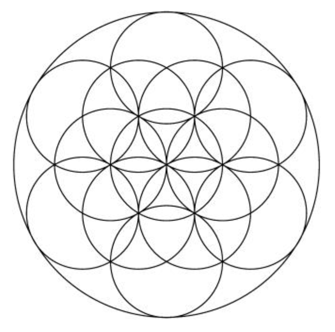
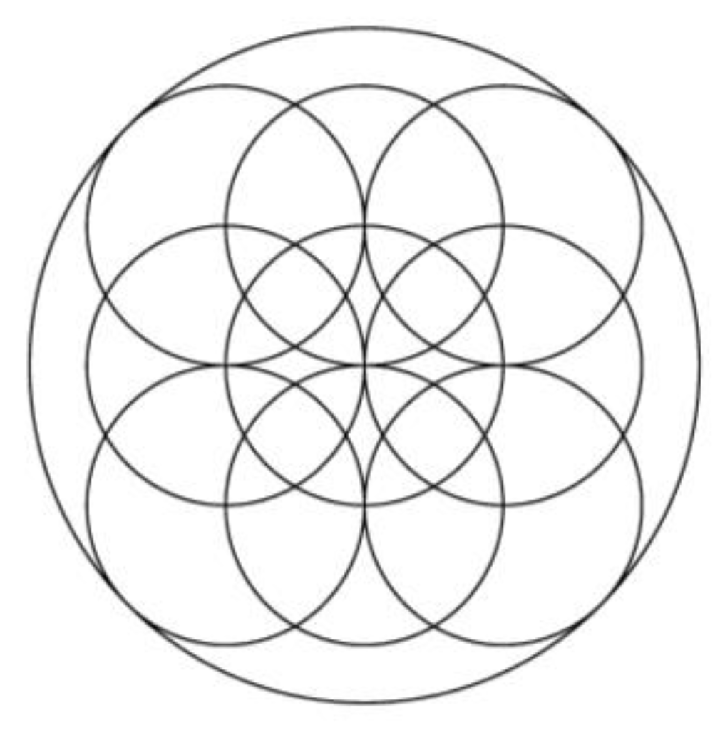
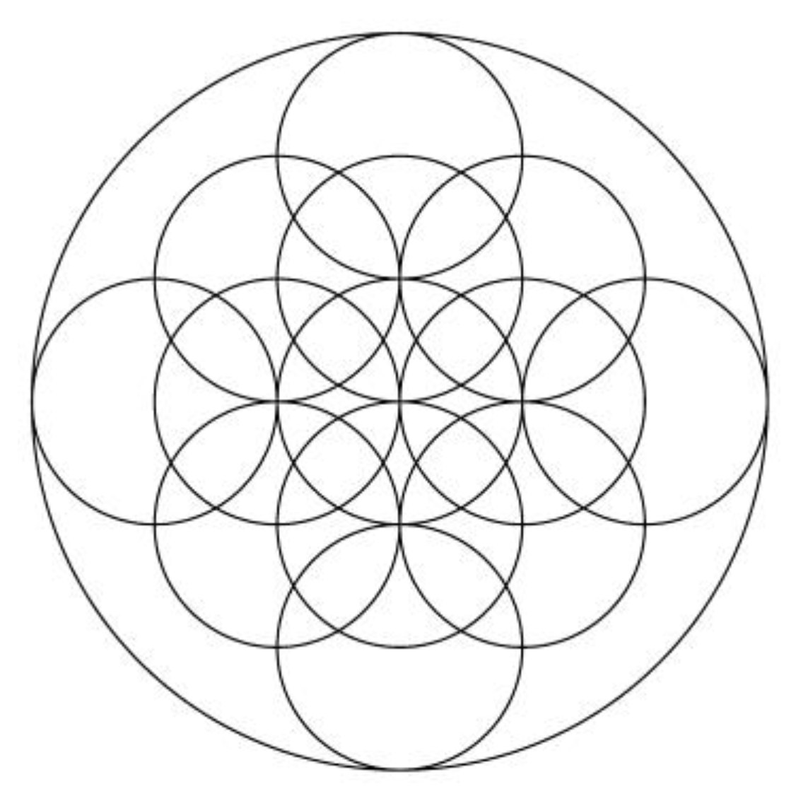
The study presented below begins with the analysis of the geometry of the Flower of Life. The complete form of this flower is shown in
Figure 1 and comprises 55 circles. A simplified version of the Flower of Life (with 13 circles) is shown in
Figure 2.
Based on the study, the authors of this paper propose two new mechanisms created to generate the Flower of Life: a six-channel Geneva mechanism completed with some kinematic chains and a second mechanism based on composite toothed gears completed with additional kinematic linkages, which provides intermittent movements and generates the flower. Then, the manual synthesis of the proposed mechanisms is made. The structure of the mechanisms and their particularities are analyzed. We choose different values for a dimensional parameter and get several figures with very beautiful designs, some identical to the Flower of Life, and others similar and much more complex than the flower. The study offers solutions for the design of the hardware component mechanisms of the machines and not for the software algorithms.
The overall purpose of the study presented in this paper is to provide new mechanisms of some machines and tools for fields such as the textile industry, toys industry, manufacture of environmental design objects, construction of architectural elements, and industrial design. The specific purpose is to create those new mechanisms capable of generating an extremely aesthetic design image—the Flower of Life.
2. Methods
First, the geometry of the Flower of Life was studied in detail, taking into account its geometric peculiarities: equal radii, positions of points, and resulting angles. The mathematical algorithm of drawing using the graphical method of the flower was established. We then looked for mechanisms that can generate the desired image, starting from knowing the kinematic possibilities of the existing mechanisms. We decided on the mechanisms with intermittent movement, choosing two of them. These mechanisms were then provided with additional kinematic linkages in order to generate the imposed curves.
We then proceeded to the structural and kinematic study of these found mechanisms. The dimensional synthesis of the mechanisms was achieved by designing the geometrical models of the mechanisms, namely, the determination of the characteristic geometric parameters. We performed a structural analysis of the mechanisms that made it possible to highlight the driving elements and the kinematic chains with the degree of mobility equal to zero, called kinematic (Assur) groups, which can be calculated independently.
Analytical methods based on finding the laws of motion in the form of mathematical functions were used to determine the mechanisms kinematic functions. This method offers high accuracy of the obtained results and is suitable for computer programming (for computer simulation of the functioning of the mechanisms). Thus, the kinematic synthesis of each proposed mechanism led to the design of an appropriate mathematical modeling, in which the requirements and configuration of the mechanism were found.
The kinematic analysis was performed with one of the most widespread analytical methods of kinematic analysis, the closed loop method. A mechanism can have one or more vectorial loops, that is, polygons, including kinematic chains linked to the base. Each of these vectorial loops was projected on the same system of axes, resulting in trigonometric equations that allowed for calculation of the coordinates of the points on the mechanism. Taking the derivative with respect to time of the relationships for positions, the components of the velocity were obtained and by a second derivation, accelerations were obtained.
Then, the trajectories generated by the proposed mechanisms were determined. The simulation of the kinematic behavior of the mechanisms was performed, computerized. Based on the relationships written by the closed loops method, we developed Gwbasic programs, so it was possible to generate the imposed curves. Further possibilities of these mechanisms were studied by changing the value of a dimensional parameter also by means of our Gwbasic programs. Finally, the geometry of the obtained images was analyzed.
3. Results and Discussions
3.1. The Geometry of the Flower of Life
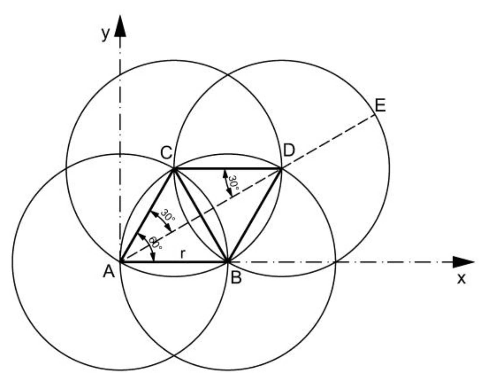
We aimed to find a way to draw the Flower of Life in
Figure 2. After studying the geometry of
Figure 2, we found the following solution (
Figure 3):
A circle with the center in A and the radius AB = r = constant is drawn (applicable to all circles which are going to be drawn);
The B circle is divided into six equal parts, establishing points B, C, and so on;
Six circles with the centers in these points and with r radius are drawn;
The circles with the centers in B and C are intersecting in point D; the intersections of the other circles similarly appear;
Another circle is drawn with the center in D and also with the r radius; this is performed similarly for the other intersection points.
Based on
Figure 3, we wrote the following relationships:
The relationship (1) gives the position of the point B, with relationships (2) and (3) determining the positions of points C and D, and relationships (4) and (5) calculation the lengths AD and AE.
The
φ angle is measured between the abscissa and AB radius, and so on, for the six chosen points on the initial circle. In
Figure 3 for the AB radius,
φ = 0.
3.2. The Obtained Results
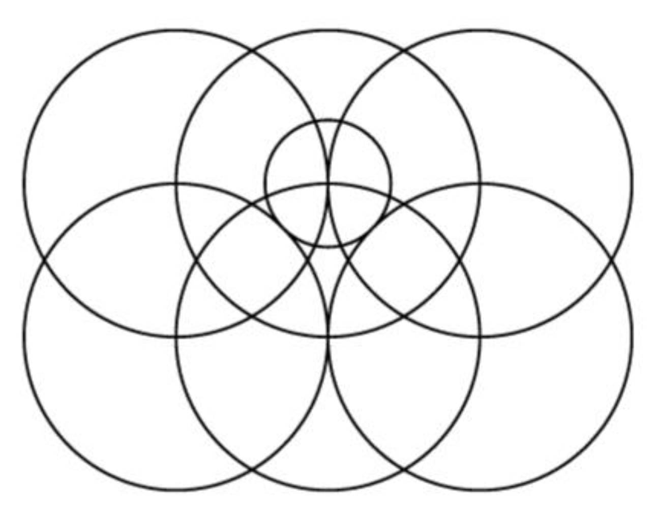
In
Figure 4, we show the central circle and the six circles. We had already obtained an aesthetic image, which is a part of the image from
Figure 2. Circles with centers in points Di were further drawn, and also the outer circle described by the point E, resulting in the final image in
Figure 5 (image with 13 circles), identical to that in
Figure 2 (but rotated). Each of these images also has the same number of 18 petals (the intersections of circles marked with gray in
Figure 2). The images in
Figure 4 and
Figure 5 were obtained with Gwbasic programs.
3.3. The Synthesis of the Generating Mechanism
The synthesis of the mechanisms consisted of determining the mechanism that ensured the obtaining of a law of motion imposed on the elements of the mechanism or the reproduction of an imposed trajectory. Generally, the synthesis of a mechanism represents a functional-kinematic design of the mechanism that involves the following stages: (a) establishing the concrete functional requirements that the mechanism must meet; (b) description of the geometrical-kinematic model of the mechanism and definition of the reference system associated with the component elements of the mechanism; (c) the transposition of the functional requirements into a suitable analytical algorithm and the achievement of the dimensional synthesis; (d) determining the kinematic functions performed by the mechanism and comparative analysis with the imposed requirements.
In the proposed study, in order to achieve the synthesis of the mechanism, we started from the condition that the AB element (
Figure 3) reaches the AC position, where it stands until the CD and DE circles are drawn, and then it passes to the next point of the six initial ones, following to stand, and so on. Taking all these into consideration we first analyzed the Geneva mechanism (also called the Maltese cross), with six standings, so cross 2 with six channels (
Figure 6). The Maltese cross is elementally driven with six straight channels arranged radially, so that the angle between two neighboring ridges of the cross should be 60°.
When rotating the driving element 1 with the angular velocity ω1, cross 2 rotates intermittently with angular velocity ω2. During the break, the circular outline of the element 1 comes in contact (with gap) with the curved outline of the cross, so the movement of the cross is prevented.
The ACDE element is linked together with the cross 2, the CD arm also being linked together with the ACE arm and cross 2. During the rotation of the cross, point C draws the central circle, and point E the outer one, arc by arc, until the two circles are complete.
The mechanism has three driving elements: the first is element 1, which drives cross 2 and the ACDE element, the second is the CG element (
Figure 7—the view from above the ACDE element), and there is an engine in C, rotating the CG element, so that G describes the G circle in
Figure 6. While the CG element draws its circle, a third driving element, DF (
Figure 7) draws the F circle in
Figure 6, in D with another electric engine. When the two elements 3 and 4 have drawn their circles, they return to the original position, stopping their movement, so the AC element will rotate to the next position. These movements will be connected by sensors that control the starting and stopping of the engines in C and D, depending on the position of the cross.
In
Figure 7, we observe that if, for example, G and F are pencils drawing circles, then they do not hit the neighboring elements, as when G draws, element 4 is on the right (the movements being linked by sensors). The variant in
Figure 7 allows for drawing on paper placed above element 4.
3.4. The Structure of the Mechanism
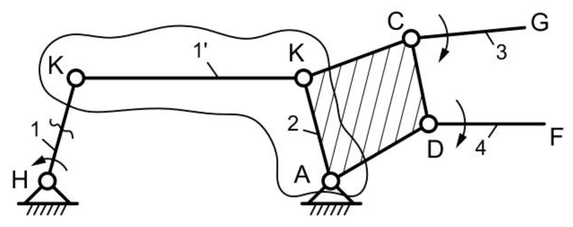
The mechanism in
Figure 6 has a higher pair in K, therefore for the structural study, this joint was replaced by element 1′ (
Figure 8) and joints K (1,1’) and K (1’,2). Elements similar to the more explicit solution in
Figure 7 are represented in the CDGF area. The structural diagram of
Figure 9 was obtained in this way.
The kinematic joints are the following: H (0,1), K (1,1′), K (1′,2), A (2,0), C (2,3), and D (2,4). The degree of mobility is:
so there are three driving elements: 1, 3, and 4. It is interesting that driving elements 3 and 4 are not linked to the base here, but to the rotational moving element 2. Nevertheless, they draw the G and F circles.
Figure 5 was generated with this mechanism.
3.5. The Synthesis of the Second Generating Mechanism
It was necessary to design a mechanism that provided the intermittent operation of a part of the mechanism. In this regard, we started from the idea of using a kinematic chain with gears with compound profiles (
Figure 10). These types of mechanisms are made of gears with incomplete teeth, some parts being replaced by different curves.
Gear 1 has only three teeth that will be in contact with the teeth of gear 2, then the cylindrical outer contour of gear 1 will come in contact with the circular arcs (the opposite direction to the circle on 1) from gear 2, so that gear 2 will stand until the teeth on 1 joints the next area with the teeth on 2. In this way, when gear 1 is continuously rotating, gear 2 will rotate intermittently by 60 degrees, being six gear areas on gear 2.
When designing the geometrical-kinematic model of the searched mechanism, it was taken into account that the generated trajectory must consist of circles of equal radii, arranged according to a certain algorithm. This imposed a condition of equality of the length of some bar type elements. The constraints of the generating points consisted of the need to be permanently on the circles on a certain level that have their centers at certain points on the circles on the lower level. The generating mechanism is shown in
Figure 11. Gears 1 and 2 are those from
Figure 10 (with the compound profile), providing intermittent rotation of element 3 (ABCD), which is a rhombus with the radius r edge, being linked to gear 2. The elements 4, 5, 6, and 7 (around these joints) are linked by the joints in A, B, C, and D, that is to say, AE, BF, DG, CH, and joints A, B, C, and D are the driving joints. The movement of these elements can be done with motors positioned in points A, B, C, and D, or by a toothed belt (12), which receives the movement from a motor in A and goes over rollers 8, 9, 10, and 11. The angle of rotation of the rhombus is
φ, and the angle
ψ is for elements 4, 5, 6, and 7.
The requirements and the configuration of the mechanism are found in the mathematical relationships written based on the closed loops method, which is an analytical method. The trajectory of the mechanism is analytically described by pairs of coordinates (x, y) of the generating points. The cartesian XY system was chosen with the origin in the rotational joint A. Since the elements of the bar type mechanism are connected by rotating joints, the relative positioning of these elements was done by means of geometric parameters of angular type. So, based on
Figure 11, we wrote the relationships:
Relationship (6) determines the position of point B, and with relationship (7) the position of point C is determined. The position of point D is determined by relationship (8), and with relationships (9) and (10) the position of the G point is determined.
3.6. The Results Obtained for the Four Point-Generating Trajectories
The simulation of the trajectories generated by the mechanism with the kinematic diagram given in
Figure 11 was achieved. The mechanism from
Figure 11, which was based on
Figure 10 and for which we wrote Equations (6)–(10), generated the curves given below. A Gwbasic program based on the above relationships was written, to obtain a wide range of curves by changing the angle k of the rhombus. This means that the gear wheels 1 and 2 are going to change, the number of the active sectors depending on the k parameter. The geometric parameter k is an angle of positioning the sides of the rhombus. This parameter is one of the parameters that defines the geometrical model of the mechanism.
The positions of the rhombus are those in
Figure 12 for k = 60°, the curves being given in
Figure 5. Different images were obtained for distinct values of the k parameter, and are presented in the following Figures. Only the aesthetic curves were kept from the multitude of the generated curves (
Figure 13,
Figure 14,
Figure 15,
Figure 16,
Figure 17 and
Figure 18) and the values of k parameter were given.
3.7. The Results Obtained for the Five Point-Generating Trajectories
We started from the generating mechanism from
Figure 11. The ABM-generating element (
Figure 19) was further added, an element jointed with AB. The MD element is connected by a rotation joint in M, describing a circle through D. The arrows indicate points that trace circles. These circles are the trajectories generated by the five driving elements articulated in the driving joints A, B, C, D, and M.
Computer simulations were performed for the trajectories generated by the mechanism of
Figure 19. The research regarding the mechanism trajectories was made for different values of the geometric parameter—the angle k. A single variable design, the geometrical parameter defined by the angle k of the rhombus ABCD, was considered.
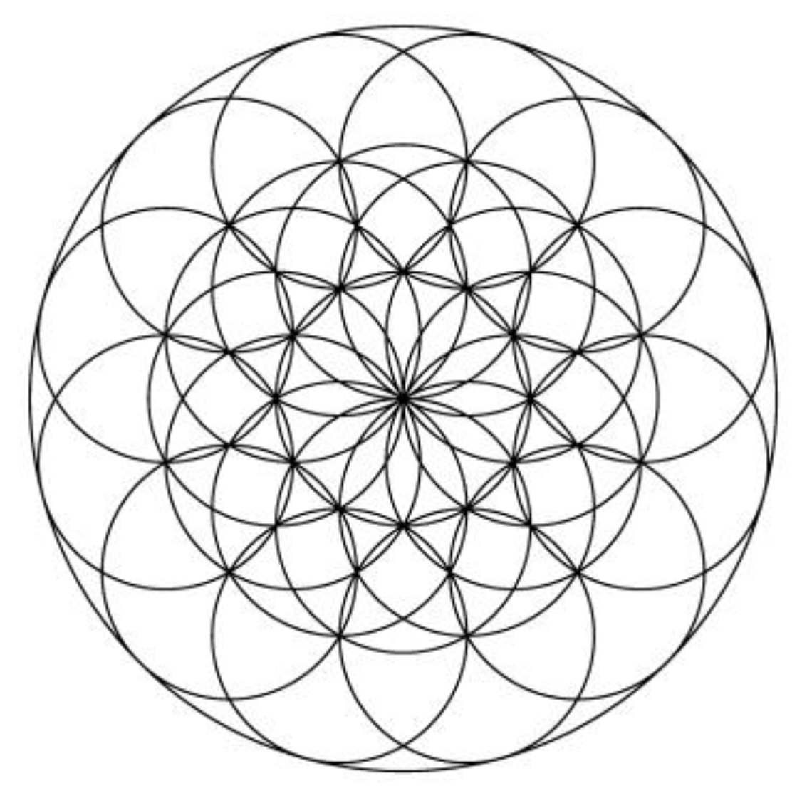
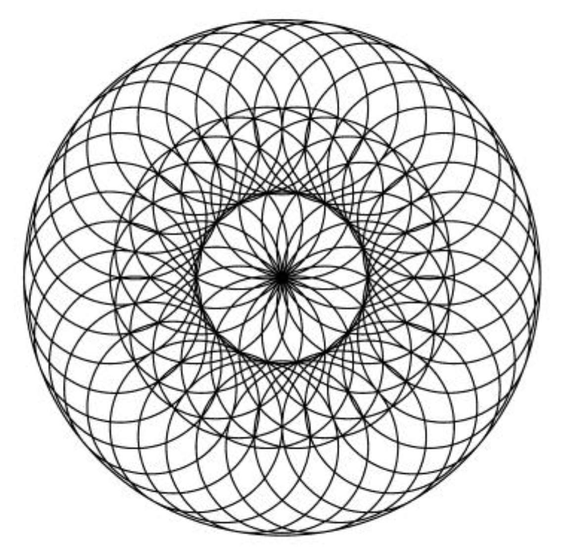
In
Figure 20, we show the image obtained for k = 60 degrees, which is much more complex than the one in
Figure 5. It can be seen that the image in
Figure 20 has 19 circles of equal radius and 30 petals resulting from the intersection of the circles. In
Figure 21, the successive positions of the rhombus and the BM element are presented, and in
Figure 22, the MD side from
Figure 19 is also presented.
The resulting images for different values of k parameter are further given (
Figure 23,
Figure 24,
Figure 25,
Figure 26,
Figure 27,
Figure 28,
Figure 29,
Figure 30 and
Figure 31). The images given in
Figure 23,
Figure 24,
Figure 25 and
Figure 26,
Figure 28 and
Figure 29 are noted by symmetry, harmony, and some by the complexity of the geometric shapes that result from the intersection of the large number of circles. In the images in
Figure 23,
Figure 24 and
Figure 25, in the central area, a symmetrical and harmonious arrangement of several geometric elements of flower petals type is noted. The same cannot be said about the images presented in
Figure 27,
Figure 30, and
Figure 31, they are not beautiful, they are ugly images.
The images shown in
Figure 20,
Figure 23,
Figure 24,
Figure 25,
Figure 26,
Figure 27,
Figure 28,
Figure 29,
Figure 30 and
Figure 31 were also generated using a Gwbasic program, created for the mechanism given in
Figure 19, based on the mathematical relationships (6–10). For example, the program for generating the image given in
Figure 20 is presented in
Appendix A.
From the presented results it can be observed that the gear mechanism with five trajectory-generating elements is capable of generating an identical image to the Flower of Life with 19 circles, as shown in
Figure 20. We also obtained images similar to the Flower of Life, such as those in
Figure 14 and
Figure 25. They look like flowers with circular corolla and have geometry based on repetitive elements, such as the Flower of Life petals, but differently arranged. Furthermore, we can observe that the mechanisms proposed in the work can generate other images with complex geometry, with symmetry, with beauty, and with many repetitive elements, which is promising for aesthetic purposes.
In the newly created mechanisms, there are several variable parameters, so that the families of images formed based on several circles arranged according to certain rules can be obtained. Several trajectories were simulated, by the variation of a single geometrical parameter of the mechanisms—the angle k of the rhombus ABCD. For both mechanisms, with four and five trajectory-generating elements, at small values of the angle k of the rhombus mechanism (k = 10, k = 20), images with more complex geometry resulted. Also, by comparing the images obtained with the mechanisms in
Figure 11 and
Figure 19, the mechanism with several trajectory generating elements (the case of the five-point trajectory-generating mechanism) could draw more complex images, with a very large number of circles. The research can be extended, for example, by changing other variable geometric parameters of the mechanisms and thus interesting geometry images can be obtained.
4. Conclusions
In this paper we found two new mechanisms capable of generating harmonious images with real aesthetic potential. The results obtained following the study and presented in the paper show that the two created mechanisms generated images (trajectories of points) that are identical to the Flower of Life. Moreover, other images similar to the Flower of Life, with great artistic potential, were obtained.
This study showed that in the newly created mechanisms (original mechanisms), there are different initial data (parameters) that can be modified and thus, different variants of the images with complex geometry and geometric symmetry can be obtained. From the obtained images, those that meet the aesthetic requirements of the potential users can be selected, based on geometric criteria or specific to the plastic arts.
During our research, we also determined less beautiful (ugly) images, without aesthetic importance, but in this paper, we gave only a few examples of these. We chose, by visual comparison, only the particularly interesting and beautiful images that the proposed mechanisms generated. Only a few examples are given in the paper, as the possibilities are vast. Further research may modify other parameters of these mechanisms and thus, new images with aesthetic potential can be obtained.
The theory of the mechanisms was integrated with computer programming instruments and thus the curves generated by the new proposed mechanisms were obtained. The images obtained through programs in Gwbasic drew attention to the significant potential and the performance of these mechanisms.
The aim of the study was achieved, the authors proposing two new mechanisms which generate a highly aesthetic design image—the Flower of Life—and providing all the notions of structure and kinematics that are necessary to calculate the mechanisms and also analyze other kinematic possibilities of the created mechanisms.
The paper contributes to the development of a new field in the Theory of Mechanisms: mechanisms generating aesthetic curves. These mechanisms may be exploited subsequently in order to obtain other images with beautiful and interesting designs.
The original mechanisms proposed in this paper might be of interest for the construction of technological equipment for areas such as the textile industry, the toy industry, environmental design object manufacture, clothing design, architecture element construction, wood object sculpture, traditional popular sawing, or industrial design.
The obtained results can help to manufacture objects and products with new and beautiful designs in which to find geometric shapes from ancient times. Currently, there is a tendency of harmoniously combining the old with the new (vintage style) in certain fields of design, and, at the same time, of using floral motifs and repetitive geometric patterns. Within this context, the importance of the study presented in this paper is increasing.

 ,
, 


