1. Introduction
Modern naval warships carry out various operations at sea, including responding to multiple threats, such as anti-ship, anti-aircraft, anti-submarine, and land threats; securing maritime control; and securing maritime transportation routes. A multitude of antennas for communication, navigation, electronic warfare, and radar are separately mounted on warships to ensure their smooth operation. An increase in the number of antennas reduces the survivability of warships due to the high radar cross section (RCS) and degrades the performance capabilities of the systems due to electromagnetic interference (EMI). Recently, the concept of an integrated mast was introduced to overcome the RCS and EMI problems [
1,
2,
3,
4]. An integrated mast can reduce RCS and EMI structurally through the use of a radome with a frequency selective surface [
5,
6]. However, traditional monopole antennas of the types widely used on warships have several disadvantages when mounted on the face of an integrated mast, such as their high-profile and weight issues [
7,
8,
9,
10]. Various antennas have been developed to realize low-profile [
11,
12,
13,
14,
15,
16,
17,
18,
19,
20]. For low-profile, the antenna is designed as a loop-type structure or with high permittivity and/or permeability materials. For example, four half loops with a bent diamond structure placed on the ground were designed with a height of 0.116
at the lowest operating frequency [
16]. In another study [
17], a monopole shaped bow-tie antenna with two top hats, two shorting pins, and a ring slot cut into the ground plane was designed with a height of 0.085
. Several ferrite structures effectively applied to the inside of a loop radiator were introduced to realize low-profile design with a height of 0.00508
[
18]. In other work [
19], a conformal ferrite dipole antenna with an electrically separated four-loop feeding structure was suggested, showing a very low-profile with a height of 0.00381
.
In this paper, an extremely low-profile ferrite dipole VHF antenna with a height of only 0.0008 is proposed for application to an integrated mast. To ensure the minimal size and weight of the antenna, 44 plate-type ferrite cells with a total weight of approximately 1.45 kg are used with the ferrite dipole antenna. The antenna is fed by an electric loop feeding structure. By applying a loop feeding structure with five loops, the magnetic distribution is changed from a triangular distribution to a quasi-uniform distribution. As a result, the gain of the antenna in the high frequency band is significantly improved. In the following sections, details of the design and performance of the proposed antenna are presented and discussed. The proposed antenna when mounted on the integrated mast of the offshore patrol vessel (OPV) is also examined.
2. Antenna Design
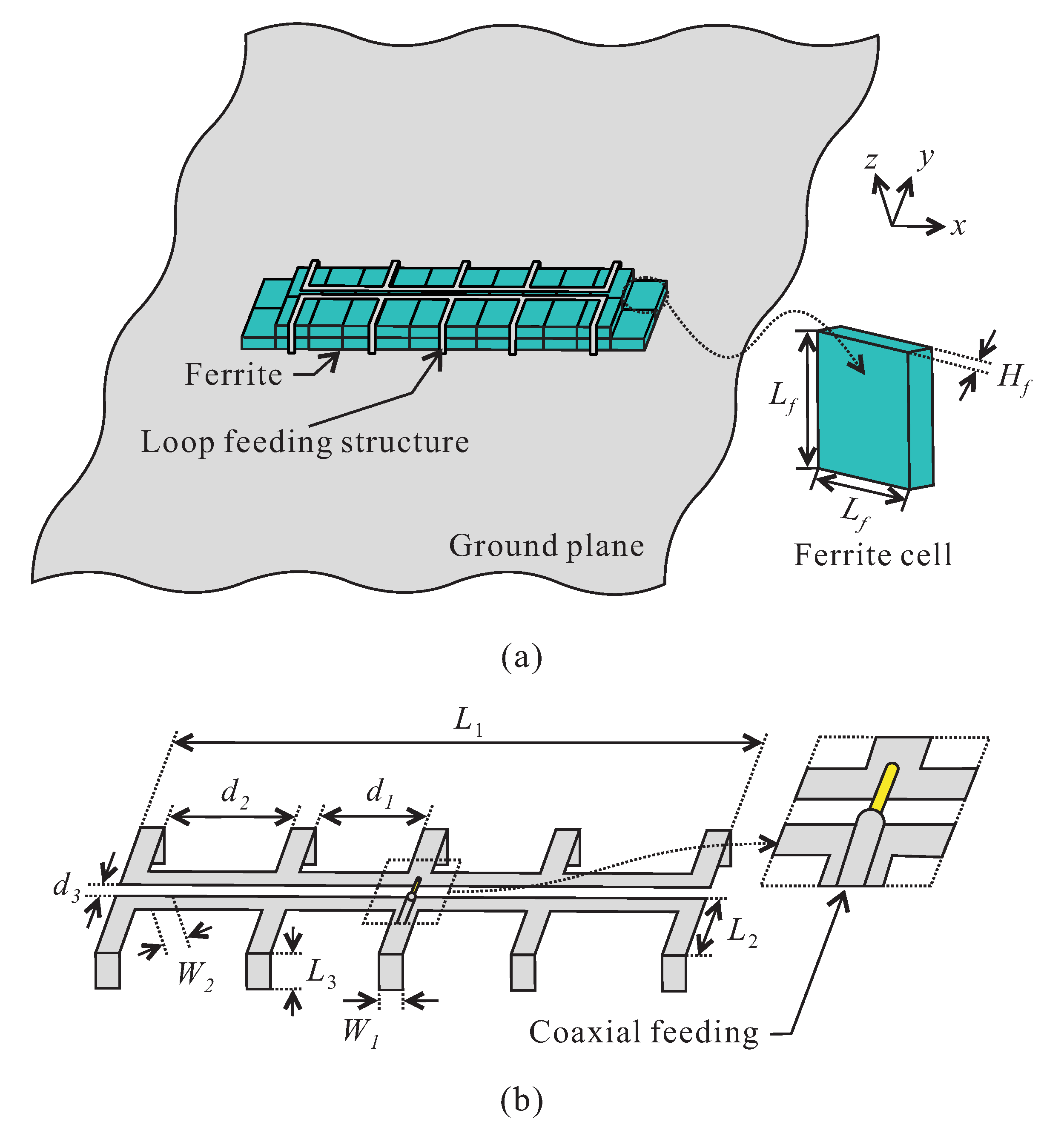
Figure 1a presents an illustration of the 3-D view of the proposed antenna, which consists of a ferrite dipole, a ground plane, and a loop-type feeding structure. The overall size of the ferrite dipole is 0.0636 × 0.0106 × 0.0005
at the lowest operating frequency. The ferrite geometry consists of 44 plate-type ferrite cells (MP2106-0M0, Laird [
21]) arranged into two stacked arrays—one with
grid cells on the bottom and one with
grid cells on the top—as shown in
Figure 1a. The dimensions of each cell are
.
Figure 1b presents the feeding structure, which consists of two long microstrip lines at the center, ten short microstrip lines, and a coaxial probe. Two long microstrip lines
in size are separated by a distance of
. Each short microstrip line is
in size with one end connected to the long microstrip line and the other end connected to the ground plane. A pair of short microstrip lines on both sides forms a one-quarter rectangular loop, and there are five one-quarter rectangular loops in total wrapped around the ferrite. The feeding structure is designed using copper tape on Styrofoam; it has a relative dielectric constant of 1.03, a loss tangent of 0.0001, and a thickness of 3 mm. The Styrofoam is directly placed on top of the ferrite cells. A coaxial probe is used to feed the ferrite antenna, and the inner and outer conductors of the coaxial probe are connected to the upper and lower arms of the one-quarter rectangular loop located at the center. The design parameters of the proposed antenna are optimized to ensure high gain performance, and the optimized values are summarized in
Table 1.
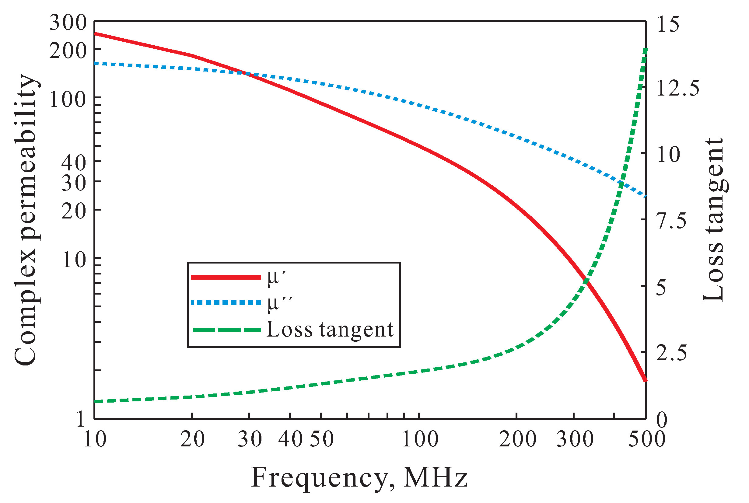
The complex permeability and magnetic loss tangent properties of the MP2106-0M0 ferrite are shown in
Figure 2. The complex permeability consists of a real part
and an imaginary part
. The magnetic loss tangent of the ferrite is calculated as
. The permittivity value of the ferrite is set to 12 in the operating frequency band (from 30 MHz to 300 MHz). As observed in
Figure 2, the
-value of MP2106-0M0 is high in the low frequency band, and the magnetic loss tangent increases sharply as the frequency increases. For magnetic dipole applications, high radiation efficiency can be obtained with a high
. Unlike a dielectric resonator antenna, the high magnetic loss tangent does not degrade the radiation efficiency of the magnetic resonator [
19]. Therefore, the ferrite MP2106-0M0 is useful in the design of a magnetic dipole antenna operating on the VHF band.
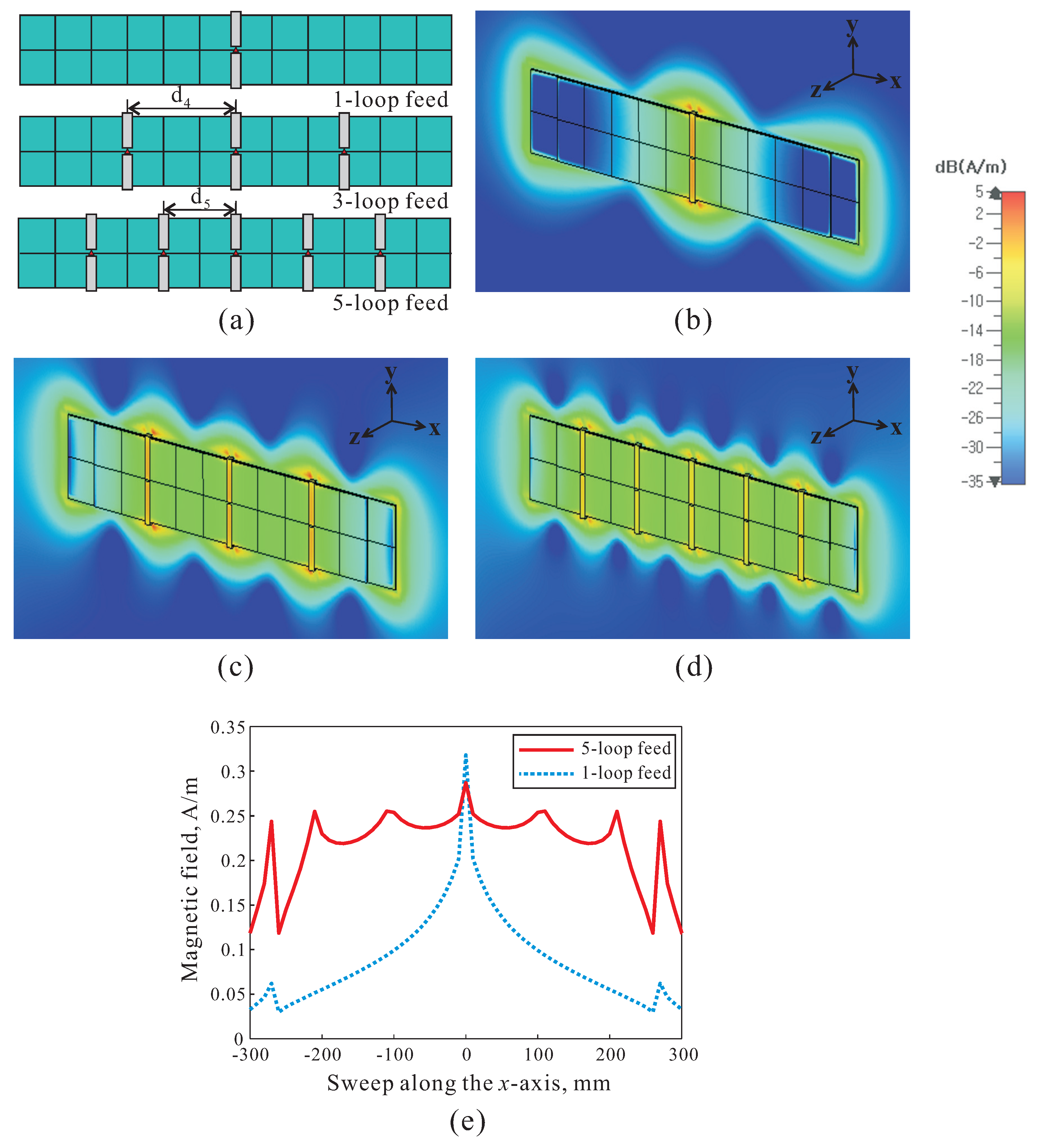
To determine how the magnetic field changes with different numbers of loop feeds, the magnetic field distribution around the ferrite dipole at 150 MHz is investigated, as shown in
Figure 3, for the 1-loop feed, 3-loop feed, and 5-loop feed. With the 1-loop feed, the loop structure is located at the center of the ferrite dipole structure shown in
Figure 3a. For the 3-loop and 5-loop feeds, there is one loop feed structure at the center, and two and four loop feeds are located on the both sides with intervals of
and
, respectively. The values of
and
are 159 mm and 106 mm, respectively. In
Figure 3b, a strong magnetic field forms around the loop feed structure and rarely extends to the side portions of the ferrite dipole. The magnetic field distribution for the 1-loop feed has a triangular distribution, like the electric field of a small dipole, which results in low radiation efficiency of the antenna. As shown in
Figure 3c,d, as the number of loop feeds increases and the magnetic fields become evenly distributed. The 5-loop feed structure is suitable to realize a uniform magnetic field distribution over the entire ferrite dipole, and therefore maximizes the radiation efficiency of the antenna. The simulated magnetic field distributions obtained along the length of the dipole (
x-axis) are shown in
Figure 3e for the 1-loop feed and 5-loop feed. Clearly, the magnetic field distribution for the 1-loop feed has a triangular distribution while that for the 5-loop feed has a nearly uniform distribution.
Figure 4 plots the simulated realized vertical-polarization gains at the main beam direction (
) for the ferrite dipole antenna on a finite ground plane with a size of 900 mm × 900 mm with different numbers of loop feeds (see
Figure 3a). The gains of the dipole antenna with the 1-loop feed and the 5-loop feed vary from −31.9 to −7.5 dBi and −31 to −1.28 dBi, respectively, in the operating band. Obviously, when the loop feed structure increases, the radiation efficiency of the antenna is increased due to the change in the magnetic field distribution. The gain of the dipole antenna with the 5-loop feed is improved considerably compared to that of the 1-loop feed due to the quasi-uniform magnetic field distribution. The maximum gain improvement is 6.4 dB at 280 MHz. The gain of the dipole antenna with the 5-loop feed is approximately 0.8 dB more than that of the dipole antenna with the 3-loop feed in the middle of its operating band.
3. Experimental Verification
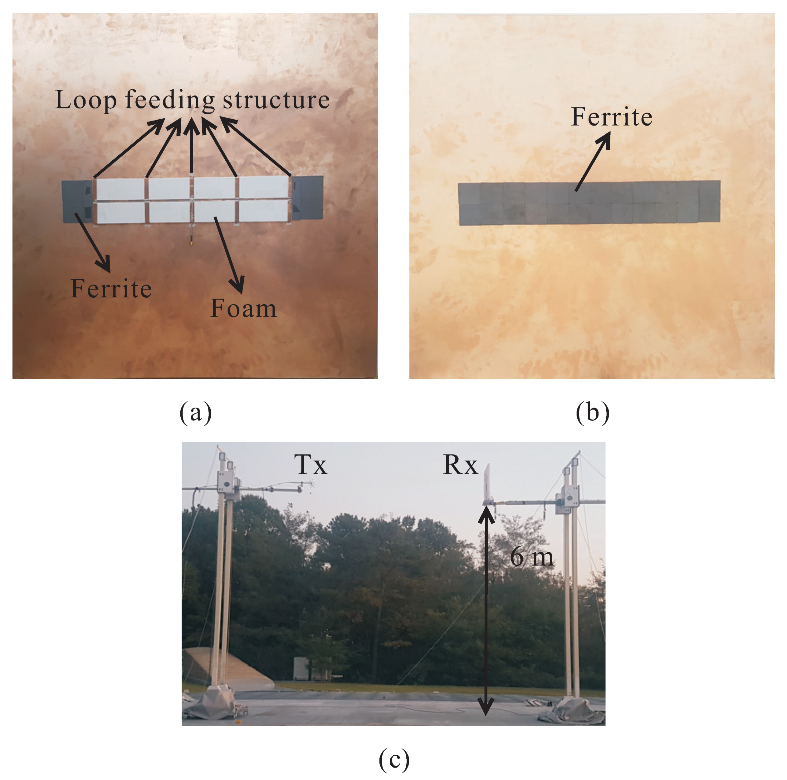
Based on the optimized design parameters, the proposed antenna was fabricated for an experimental demonstration.
Figure 5a shows a photograph of the fabricated antenna. The antenna has a total weight of 1.45 kg and electrical dimensions of approximately 0.0636
0.0112
0.0008
at the lowest operating frequency of 30 MHz. The antenna is mounted at the center of a finite ground plane with a size of 900 mm × 900 mm. The ferrite cells are attached to the ground plane using double-sided tape (see
Figure 5b). To simplify the fabrication, the conductor of the loop feeding structure is made of copper tape and is directly attached onto the Styrofoam covering the ferrite dipole structure. The loop feeding structures are connected to the ground plane by silver conductive epoxy (CW2400, Chemtronics). The inner and outer conductors of the coaxial cable are correspondingly connected to the upper and lower arms of the one-quarter rectangular loop, which is placed at the center by soldering.
Figure 5c presents a picture of the antenna measurement set-up. Radiation patterns were measured at the outdoor measuring station of the Korea Research Institute of Standards and Science. The proposed antenna was used as a receiving antenna (Rx), and both the transmitting (Tx) and receiving (Rx) antennas are positioned 6 m above the ground.
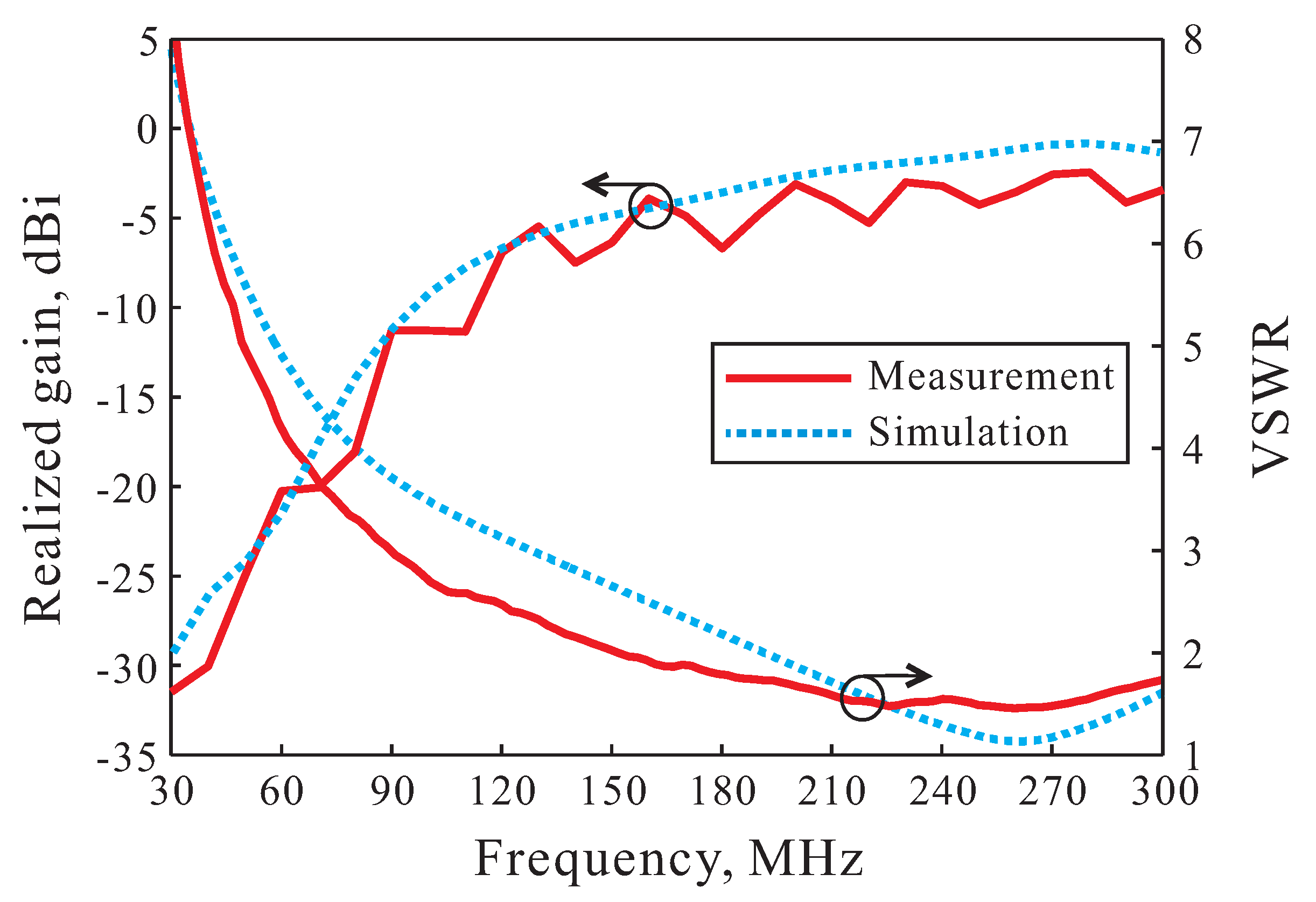
Figure 6 presents the simulated and measured results of the Voltage Standing Wave Ratio (VSWR) and the realized gains of the proposed antenna. The measurement of the VSWR was done using an Agilent 8510C vector network analyzer. As observed in
Figure 6, the simulated and measured results of the VSWR are in good agreement in the entire operating frequency band. The simulated and measured realized gains in the broadside direction (
= 0
) range from −29.26 to −0.83 dBi and from −31.48 to −2.44 dBi, respectively. The slight discrepancies between the simulated and measured results are mostly caused by fabrication imperfections and/or experimental tolerances due to calibration and reflected and scattered waves from the ground.
Table 2 shows a comparison of certain key features between the proposed ferrite dipole antenna and a previous VHF antenna described in the literature [
18,
19,
20]. Clearly, the antenna presented here has a much lower height and a lighter weight as compared to the antennas reported in earlier studies. Compared to other designs [
18,
20], the proposed antenna provides a much higher gain. Although one earlier design [
19] has a higher gain, the proposed antenna is smaller and has a much lower height. This makes the proposed antenna an extremely low-profile, lightweight, and high-gain VHF antenna that is very suitable for integrated mast applications.
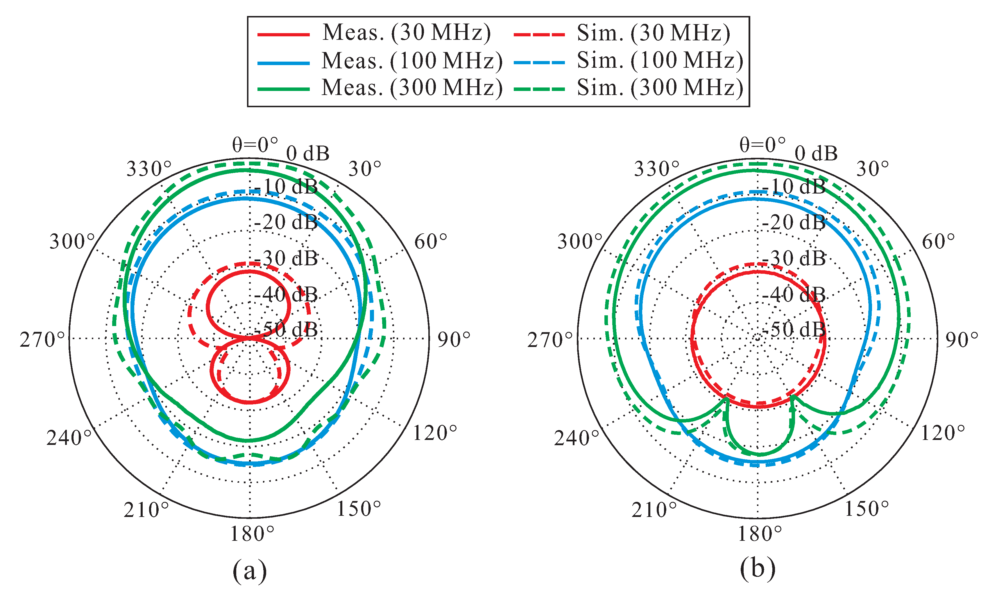
Figure 7 shows the simulated and measured radiation patterns at three different frequencies of 30, 100, and 300 MHz on the
-(
= 0
) and
-(
= 90
) planes. The dashed and solid lines represent the results of the simulation and the measurement, respectively. The values of the radiation patterns indicate the vertical-polarization gains of the proposed antenna. It can be observed that the proposed antenna radiates omnidirectional and directional waves in the low and high frequency bands, respectively. In addition, the simulated and measured results of the radiation patterns are in good agreement.
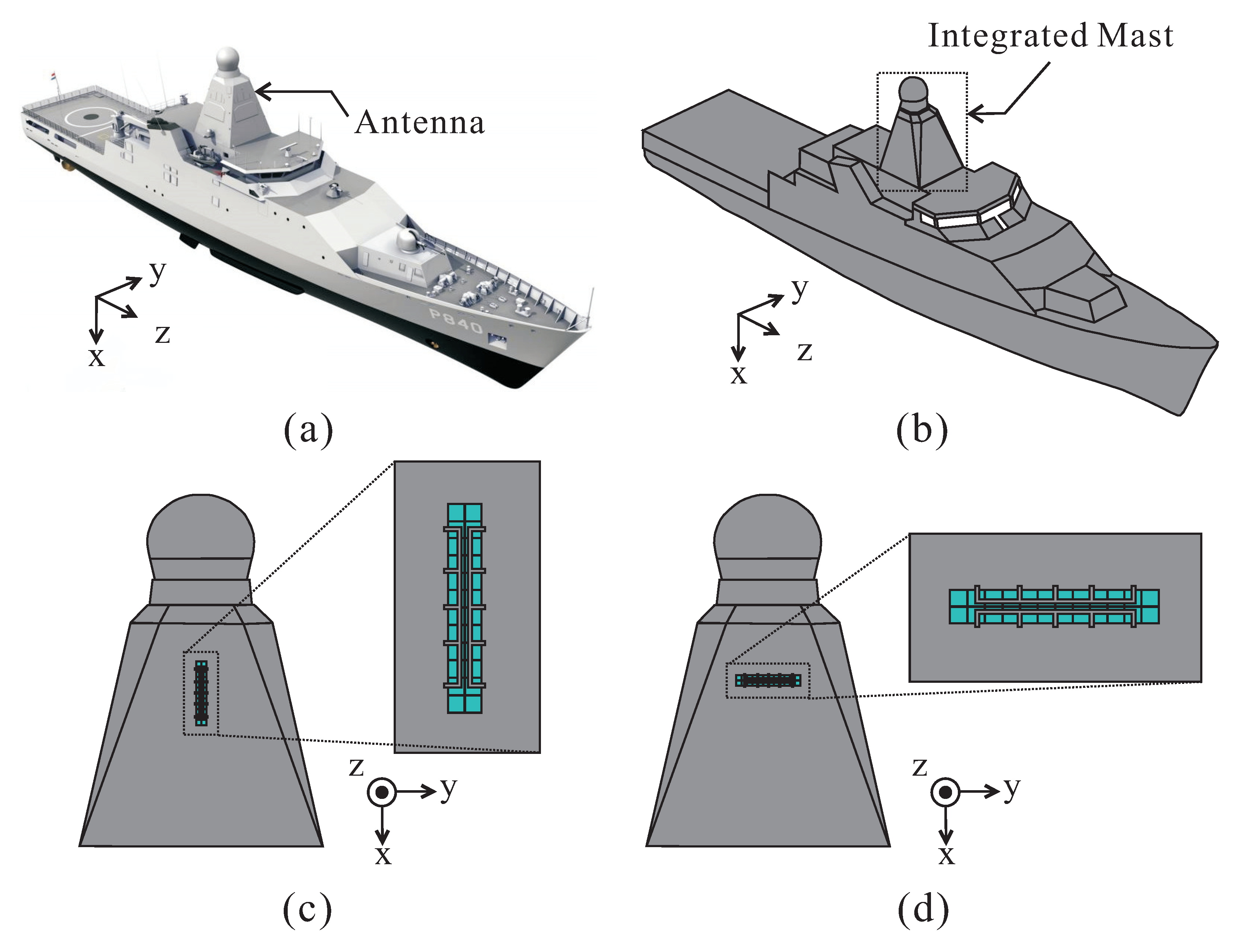
Figure 8a shows a photograph of a Holland-class OPV of the Royal Netherland Navy with an integrated mast. To examine the performance of the proposed antenna mounted on the integrated mast in this case, the shape of the OPV is modeled simply (see
Figure 8b). The length and beam of the OPV are 108.4 m and 16 m, respectively, and all surfaces are implemented as conductors. The proposed antenna is mounted on the integrated mast of the OPV with vertical (in
x-axis) and horizontal (in
y-axis) arrangements, as shown in
Figure 8c,d, respectively.
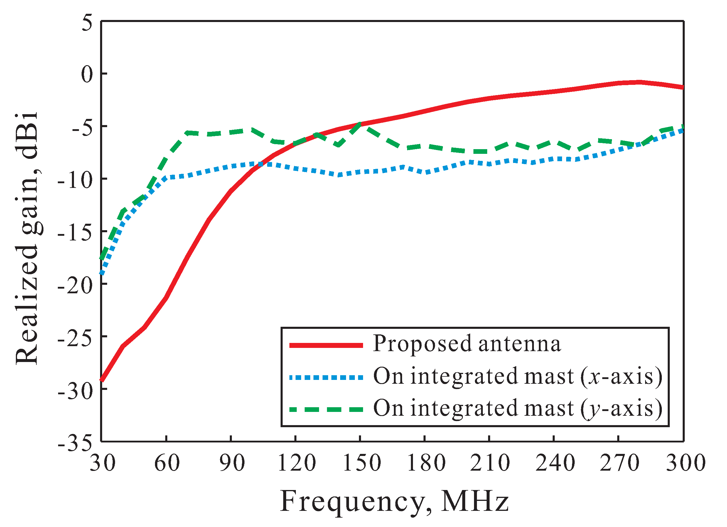
Figure 9 presents the simulated realized gains of the proposed antenna when mounted on the integrated mast of an OPV. The simulated realized gains of the ferrite dipole antenna on the finite flat ground plane (as shown in
Figure 6) is also illustrated here as a reference. By mounting the proposed antenna on the integrated mast, the overall structure of the OPV becomes the ground of the antenna. With an integrated mast, the realized gains at low frequencies are higher than that of the proposed antenna due to a significant increase in the size of the ground plane. However, at high frequencies, the realized gains are reduced as compared to that of the proposed antenna. This is mainly due to the electromagnetic waves scattered by the structure of the OPV. The realized gains of the proposed antenna on the integrated mast on the
x-axis and
y-axis vary from −19.13 to −5.39 dBi and from −17.69 to −4.82 dBi, respectively.
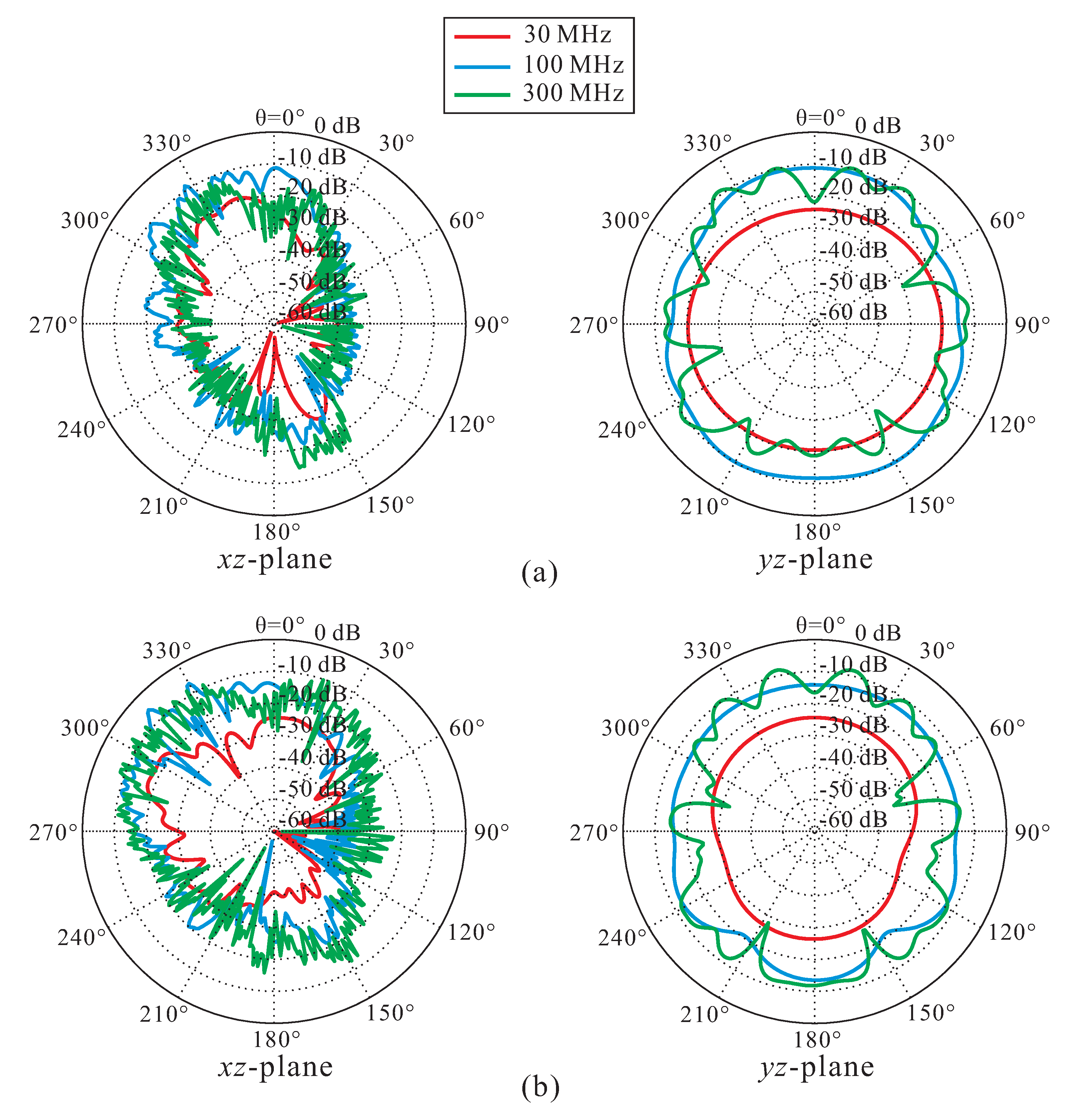
Simulated far-field radiation patterns of the proposed antenna mounted on the integrated mast of an OPV on two cutting planes (
-plane,
-plane) are depicted in
Figure 10. It can be seen that the radiation patterns are influenced less by the OPV structure at 30 MHz due to the long wavelength; however, when the frequency is increased, the radiation patterns are influenced more by the OPV structure. The
-plane and
-plane patterns are directional and omnidirectional patterns, respectively. The proposed antenna is mounted on the front of the integrated mast, and the radiated directional wave is realized in the
-direction. Due to the influence of the bow of the OPV, the directional pattern is tilted toward the
-direction.

 ,
, 


