Article

Railway Polygonized Wheel Detection Based on Numerical Time-Frequency Analysis of Axle-Box Acceleration

1
Key Laboratory of Traffic Safety and Control of Hebei Province, School of Traffic and Transportation, Shijiazhuang Tiedao University, Shijiazhuang 050043, Hebei, China
2
School of Civil Engineering, Southwest Jiaotong University, Chengdu 610031, Sichuan, China
3
Structure Health Monitoring and Control Institute, Shijiazhuang Tiedao University, Shijiazhuang 050043, Hebei, China
*
Author to whom correspondence should be addressed.
Appl. Sci. 2020, 10(5), 1613; https://doi.org/10.3390/app10051613
Submission received: 28 January 2020 / Revised: 19 February 2020 / Accepted: 21 February 2020 / Published: 28 February 2020

Abstract

:
The increasing need for repairs of polygonized wheels on high-speed railways in China is becoming problematic. At high speeds, polygonized wheels cause abnormal vibrations at the wheel-rail interface that can be detected via axle-box accelerations. To investigate the quantitative relationship between axle-box acceleration and wheel polygonization in both the time and frequency domains and under high-speed conditions, a dynamics model was developed to simulate the vehicle-track coupling system and that considers both wheel and track flexibility. The calculated axle-box accelerations were analyzed by using the improved ensemble empirical mode decomposition and Wigner-Ville distribution time-frequency method. The numerical results show that the maximum axle-box accelerations and their frequencies are quantitatively related to the harmonic order and out-of-roundness amplitude of polygonized wheels. In addition, measuring the axle-box acceleration enables both the detection of wheel polygonization and the identification of the degree of damage.

1. Introduction

The high-speed train system is rapidly developing in China and, as a result of rolling contact and vibration impact, wheel polygonization, which is a type of railway-wheel out of roundness (OOR), is now a growing problem. Wheel-tread polygons have been detected with radial irregularity wavelengths from 0.12 to 3.4 m (which is approximately equal to the circumference of a wheel) and with 1to 25 harmonic orders around the wheel circumference.
In the early 1980s, Kreuzen described wheel polygons observed in the Dutch railway system [1]. Wheel polygons can be both dangerous and annoying: the serious Eschede accident of an Inter City Express train in Germany in the summer of 1998, in which 101 people were killed and 194 injured, was attributed to a fatigue crack in a wheel rim caused by a wheel polygon. In recent years, failures in vehicle system components have appeared in the Chinese high-speed railway system, such as gearbox cracks [2], bolt fracture at the axle-box cover and brake disk [3], and other fastener failures that are caused by high-frequency impact due to wheel polygons. In addition, a periodic wheel out-of-roundness leads to noise and vibration levels that annoy passengers, especially at certain train speeds.
The maximum vertical wheel-rail contact force is increased by wheel OOR, leading to fatigue and reducing the life span of the track and vehicle components, such as wheelset bearings, gearbox, bolts, fastenings, and sleepers [4]. Trained workers are required to analyze wheel polygons by means of a roughness-measuring system such as m|Wheel, which is time-consuming and not particularly precise. Thus, it is essential to develop procedures for real-time, on-line detection of OOR and to find suitable countermeasures.
Different approaches for detecting OOR have been reported, including vibration-impact measurement, displacement determination, image and ultrasonic telemetering, laser sensing, and noise detection. For example, Lutzenberge and Wu [5] discussed the Müller-BBM wheel monitoring system allowing for the detection of wheel tread damages. The system, with sensors installed at several track sections to record rail vibration, can identify wheel flats or polygons of all approaching vehicles in an early stage. Much research has been devoted to detect wheel defects based on wheel-rail interaction and track response [6,7,8]. Lee and Chiu [9] compared three methods of predicting impact force on a railway track-like structure using both finite element and experimental techniques. The results indicated that measuring strain was an effective method of reconstructing dynamic impact force, but that efficacy would be reduced as the impact force increased. Wei et al. [10] described a real-time out-of-roundness wheel-defects monitoring system based on track strain response by using Fiber Bragg Grating sensors. Wayside monitoring systems based on acoustic [11] and ultrasonic [12] sensors have also been employed to detect wheel conditions. However, these sensors can be influenced by electromagnetic interference under a railroad environment. Besides, polygonal-wheel or local spall-wheel defects cannot be detected. Sensors based on Laser-PSD (Position Sensing Detector) technology to measuring out-of-roundness wheel set on-line was reported in [13]. The system can determine the size of wheel out-of-roundness by detecting the displacement of a light spot in PSD based on track dynamics. However, the Laser-PSD sensor requires a precision setup, which is difficult in practice. For most of these measurement systems, the sensors are positioned on rails or sleepers, mainly for OOR detection at speeds below 200 km·h−1.
Vehicle vibrations caused by wheel and track defects affect axle-box accelerations, so some research has been done on using axle-box accelerations to identify short track defects, such as squats, rail spalling, rail corrugation, and track irregularities in several wavelength ranges, and also for more general track surveying. For example, in the late 1990s Coudert [14] described an easy-to-measure method to detect track irregularity of short wavelength by using axle-box acceleration. Tanaka and Furukawa [15] reported a cheap and robust method for estimating wheel load and lateral force caused by short-wavelength track irregularity based on axle-box acceleration measurement, which is difficult to detect with a track inspection car. In particular, they analyzed the relationship between the wheel load, lateral force, and axle-box acceleration of the Shinkansen train. The study revealed that the maximum values of the wheel load and lateral force can be estimated by the use of axle-box acceleration. Molodova et al. [16] discussed the application of axle-box acceleration measurements to assess squats and insulated joints, and determined the quantitative relationship between track defects and the characteristics of excited axle-box acceleration through a finite element model. Salvador [17] detected track defects and track singularities with the aid of axle-box acceleration measurement, and did testing on the Metropolitan Rail Network of Valencia, Spain. The results determined the location of accelerometers on the train and identified track singularities and diverse track defects. However, little research has been reported on the quantitative correlation between wheel polygons and axle-box acceleration. Although Li et al. [18] used axle-box acceleration to detect wheel flats and other wheel damage, they could not assess the damage level of polygonized wheels. One promising, low cost, and relatively simple technique to determine wheel conditions is by detecting axle-box acceleration, so detecting axle-box accelerations for high-speed trains and their time-frequency characteristics merits further study to develop a method to detect wheel polygons.
To detect wheel defects based on axle-box acceleration signal analysis, applying appropriate vibration signal processing techniques is essential to determine the state of wheel polygons. Axle-box acceleration signals caused by polygonized wheels are non-stationary and nonlinear. In the past decades, researchers have proposed several random vibration signal processing approaches, such as short-time Fourier transform (STFT), wavelet transform (WT), Hilbert-Huang transform (HHT), and the Wigner-Ville distribution (WVD). However, the constant time and frequency resolution of STFT make it unsuitable for analyzing a non-stationary signal. In contrast, the time and frequency resolutions of WT are adaptive. For example, Caprioli et al. [19] offered a wavelet survey applied for track diagnosis based on acceleration signal analysis of a running train, discussed the advantages and drawbacks of the discrete wavelet transform, the continuous wavelet transform and the wavelet packets, with respect to the classical Fourier analysis. Jia and Dhanasekar [20] proposed the wavelet local energy averaging approach and average signal wavelet decomposing application for rail wheel flats onboard detection using train acceleration signals. The numerical simulation results demonstrated that the proposed method was effective for monitoring localized rail wheel flats with sizes smaller than predefined threshold. Nevertheless, it is difficult to choose the mother wavelet at present. HHT is an adaptive method for time-frequency analysis, including empirical mode decomposition (EMD) and Hilbert transformation. Li et al. [18] utilized HHT based method to analyze axle-box vibration signal characteristics induced by railway out-of-round wheels. An energy principle algorithm was proposed to suppress mode-mixing phenomenon. The study results show that the revised HHT can be adopted to distinguish out-of-round wheels from normal wheels. However, the mode-mixing problem caused by the intermittent signal in the sifting EMD process still requires attention. Wigner-Ville distribution (WVD) is an ideal approach for a three dimensional representation of non-stationary signals in the time-frequency-amplitude domain, which is effective for monitoring machinery under non-stationary conditions [21]. Liang et al. [22] presented a mixed approach of adaptive noise cancelling (ANC) and time–frequency signal analysis application for detection of wheel flat and rail surface defect. The experimental results show that the combination of ANC technique and WVD can extract weak signals and effectively suppress noises for fault diagnosis. Although the WVD is a valuable tool for time-frequency signal analysis, the cross-term interference problem is the main limitation for its application [23]. Based on the above discussion, a joint time-frequency method based on improved EMD (called the “ensemble EMD”, or EEMD) and the WVD is proposed to extract characteristics from axle-box acceleration signals. This approach minimizes cross-term interferences and permits an adaptive time-frequency-amplitude representation.
The aim of this paper is thus to present an analysis of axle-box vibration acceleration using the joint time-frequency method to determine the essential information relating to polygon wheel defects. The first step of this study is to provide quantitative theoretical analysis of the relation between axle-box accelerations and polygonal wheel defects. Then follows the simulation of dynamic responses of axle-box acceleration due to wheel polygons. Based on the theory of vehicle-track coupling dynamics, a dynamic numerical train-track coupling model is developed that considers both elastic wheelsets and elastic tracks implemented in Universal Mechanism (UM) and finite-element analysis (ANSYS) software. The results form a basis for detecting various polygon wheel defects for high-speed railways. Finally, the signal processing of axle-box acceleration signals is performed based on improved EMD and WVD joint time-frequency approaches.

2. Theoretical Analysis

Figure 1 illustrates a parameter-lumped simple wheel-track model that considers wheel OOR to analyze the axle box vibration caused by wheel polygons. In this model, v is the vehicle velocity, m1 is the unsprung mass, z1 is the vertical displacement of the wheelset, k1 is related to the vertical stiffness of the primary spring, m2 is the mass of the track, k2 is the vertical stiffness of the track, c2 is the track damping, and z2 is the vertical displacement of the track. The downward direction is positive.
Based on conservation of energy, a track may be conceptually modeled as an infinite beam with dampers on an elastic foundation. The track model allows for deflections and forces in the z direction. The parameters of the elastic foundation beam are converted into equivalent mass, equivalent damping, and an equivalent spring attached to each wheel. For a train with a polygonal wheel of a given OOR amplitude a rolling along the track at speed v, the vertical dynamic equations for the wheel-rail system are
{ m 1 z ¨ 1 + k 1 ( z 1 a z 2 ) = 0 m 2 z ¨ 2 + c 2 z ˙ 2 + k 2 z 2 k 1 ( z 1 a z 2 ) = 0
The solution to the numerical ordinary differential Equation (1) is
{ z ¨ 1 ω 1 2 + z 1 z 2 = a z ¨ 2 ω 2 2 + c 2 k 1 z ˙ 2 + ( k 1 + k 2 k 1 ) z 2 z 1 = a
where ω 1 = k 1 / m 1 , ω 2 = k 1 / m 2 , and z ¨ 1 is the axle-box acceleration.
The initial irregularity of the wheel polygon is defined by a harmonic displacement function
a ( t ) = a sin ( ω t + φ )
where a(t) is the time-dependent OOR amplitude, ω is the frequency corresponding to the harmonic orders of the OOR, and φ is the phase angle between the two wheels on the same axle.
The Laplace transform of Equation (3) is
a ( s ) = a ( s sin θ + ω cos θ ) s 2 + ω 2
To obtain transfer functions of z1 and z ¨ 1 induced by a ( t ) , we use
{ z 1 ( s ) = H z 1 ( s ) a ( s ) z 2 ( s ) = H z 2 ( s ) a ( s )
where z1(s) and z2(s) are the Laplace transforms for z1 and z2, respectively. H s 1 ( s ) and H s 2 ( s ) are the transfer functions corresponding to z1 and z2 under excitation a ( t ) .
When the initial state is zero, we get the Laplace transform of Equation (2):
{ ( s 2 ω 1 2 + 1 ) z 1 ( s ) z 2 ( s ) = a ( s ) z 1 ( s ) ( s 2 ω 2 2 + c 2 s k 1 + k 2 k 1 + 1 ) z 2 ( s ) = a ( s )
Using Equation (5) in Equation (6) gives
H z 1 ( s ) = s 2 ω 2 2 + c 2 s k 1 + k 2 k 1 s 4 ω 1 2 ω s 2 + c 2 s 3 k 1 ω 1 2 + [ 1 ω 2 2 + ( k 2 k 1 + 1 ) 1 ω 1 2 ] s 2 + c 2 s k 1 + k 2 k 1
When the initial state is zero, the Laplace transform of z ¨ 1 is
z ¨ 1 ( s ) = s 2 z 1 ( s ) = s 2 H z 1 ( s ) a ( s ) = s 4 ω 2 2 + c 2 s 3 k 1 + k 2 s 2 k 1 s 4 ω 1 2 ω 2 2 + c 2 s 3 k 1 ω 1 2 + [ 1 ω 2 2 + ( k 2 k 1 + 1 ) 1 ω 1 2 ] s 2 + c 2 s k 1 + k 2 k 1 a ( s sin θ + ω cos θ ) s 2 + ω 2
Because 1 ω 1 2 ω 2 2 , c 2 k 1 ω 1 2 , [ 1 ω 2 2 + ( k 2 k 1 + 1 ) 1 ω 1 2 ] , c 2 k 1 , and k 2 k 1 are all positive, the Routhcriterion is satisfied, and the characteristic equation becomes
s 4 ω 1 2 ω 2 2 + c 2 s 3 k 1 ω 1 2 + [ 1 ω 2 2 + ( k 2 k 1 + 1 ) 1 ω 1 2 ] s 2 + c 2 s k 1 + k 2 k 1 = 0
The necessary and sufficient condition for all roots having negative real parts is
z ¨ 1 ( s ) = i = 1 4 A i s + p i + B s + C s 2 + ω 2
where Ai, pi, B, and C are all constants related to ω1, ω2, c2, k1, k2, and ω.
Thus, the inverse Laplace transformation is given by
z ¨ 1 = i = 1 4 A i e p i t + D cos ( ω t + φ )
For Equation (11), the first item is an exponential attenuation function independent of frequency, and, after a long time ( p i t < < 1 ), the second term gives z ¨ 1 for zero phase angle between the two wheels on the same axle (φ = 0).
Based on Equation (11), it can be concluded that the frequency of the axle-box acceleration z ¨ 1 is the same as the characteristic frequency of the wheel polygon, which shows that it is reasonable to analyze and identify wheel polygon defects based on axle-box vibration.

3. Modeling and Signal Analysis Method

3.1. Vehicle-Track Rigid-Flexible Coupling Dynamics Model

In order to simulate the dynamic responses of axle-box acceleration to polygonal wheel defects, consider as an examplea high-speed electric multiple unit vehicle and a China Railways Track Structure (CRTS) II slab ballastless track of the Chinese high-speed railway lines [24]. Based on the mechanical model of the vehicle-track coupled system shown in Figure 2a, a numerical model of a vehicle-track coupling system was developed, representing a passenger car running on a slab track. The simulation is implemented by using both Universal Mechanism (UM) and ANSYS software.
The vehicle model consists of one rigid car body, two rigid bogies, and four elastic wheelsets. The car body, bogies, and wheelsets are connected by linear springs and viscous dampers representing the primary and secondary suspensions. The vehicle can have vertical, lateral, and longitudinal motion. The polygonized wheels are suspected of producing vibrationsin the middle- and high-frequency ranges [25]. Therefore, a finite-element model in the ANSYS environment is used to calculate the model wheelset parameters by treating the wheelsets as flexible bodies. The wheel tread is of LMA worn type, and the wheel polygonsaredescribed by sinusoidal functions to determine the harmonic deviation of the wheel radius from a constant value [4]. For the flexible-track model, we transform the CRTS II slab ballastless track finite-element model into UM. The finite-element model of the CRTS II slab ballastless track is composed of two CHN60 rails, a concrete slab layer, a concrete-asphalt (CA) mortar filling layer, and afoundation, which are all represented by three-dimensional solid elements in ANSYS. The fasteners connecting the rails and the concrete slab layer are modeled as spring elements. The connections between the three layers (i.e., concrete slab layer, CA mortar layer, and the foundation) are modeled as contact elements. Figure 2b shows an enlarged view of the flexible wheelsets and tracks, and Table 1 lists the parameters of the vehicle and track systems [24].
The vertical wheel-rail contact forces are calculated by using the Kik-Poitrowski model, which considers the nonlinear contact mechanics between wheel and rail. Creep and tangential forces in the contact area are calculated by using Kalker’s linearized theory.
The vehicle-track rigid-flexible coupling dynamics model is validated in [26].

3.2. Joint Time-Frequency Method based on EEMD and WVD

In order to investigate the simulated axle-box acceleration signals in the time-frequency domain, an efficient algorithm based on EEMD and WVD is proposed: by decomposing a noise-assisted multi-component signal into a number of intrinsic mode functions (IMFs), and then analyzing by using the Wigner-Ville transformation, one cannot only suppress cross-term interference but also exploit the advantages of the WVD.
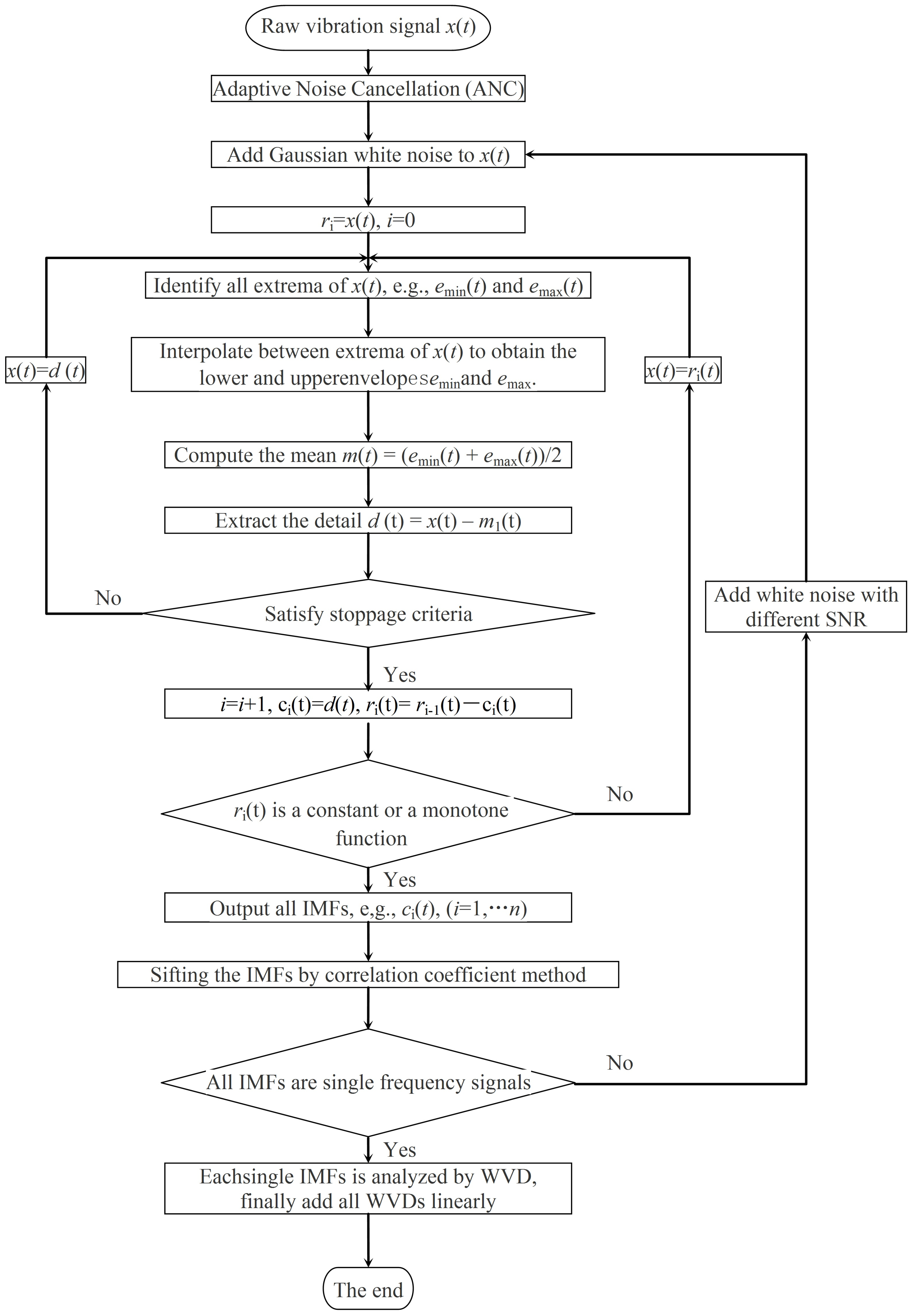
Figure 3 shows a flowchart describing the methodology to identify wheel polygons. First, to remove additive noise or unwanted signals from the raw vibration signals, adaptive noise cancellation [22] is used to pre-process the raw signal. Vibration signals caused by rail irregularities are then filtered and noise is reduced by using an adaptive filter.
Next, add Gaussian white noise to the original vibration signal x(t) and decompose the conditioned signal by EEMD into a series of IMFs and a residual:
x ( t ) = i = 1 n c i ( t ) + r n ( t )
where ci(t) is an IMF, i is the number of modes, and rn(t) is the corresponding residual. The stopping criteria for terminating the sifting process in Figure 3 are: (1) that the number of extrema and the number of zero-crossings must differ at most by one, and (2) that the mean between the upper and lower envelopes can be considered to be zero. The disadvantage of EEMD is that the signatures overlap in both time and frequency because the extremes identify x(t). The correlation coefficient method [25] is thus used to eliminate false IMFs by a sifting process.
Third, the remnant IMFs are analyzed by using the WVDas follows:
W V D x ( t , f ) = c ( t + τ / 2 ) c ( x τ / 2 ) e j f τ d τ
where f is the frequency, τ is the integration variable, and the asterisk (*)indicates complex conjugation. Finally, the WVDs are summed together to reconstruct the WVDs of the original signal:
W V D x ( t , f ) = W V D C 1 ( t , f ) + W V D C 2 ( t , f ) + + W V D C n ( t , f ) = i = 1 n W V D C i ( t , f )

4. Results and Discussions

4.1. Results of Axle-Box Vibration Acceleration Caused by Wheel Polygons in Time-Domain

4.1.1. Effect of Wheel Polygon

In the section, we present some numerical results showing how the axle-box vibration is related to types of wheel polygons, and examine the time dependence of the vertical acceleration of the axle-box induced by wheel polygons, as derived from the numerical model in Section 3.1.
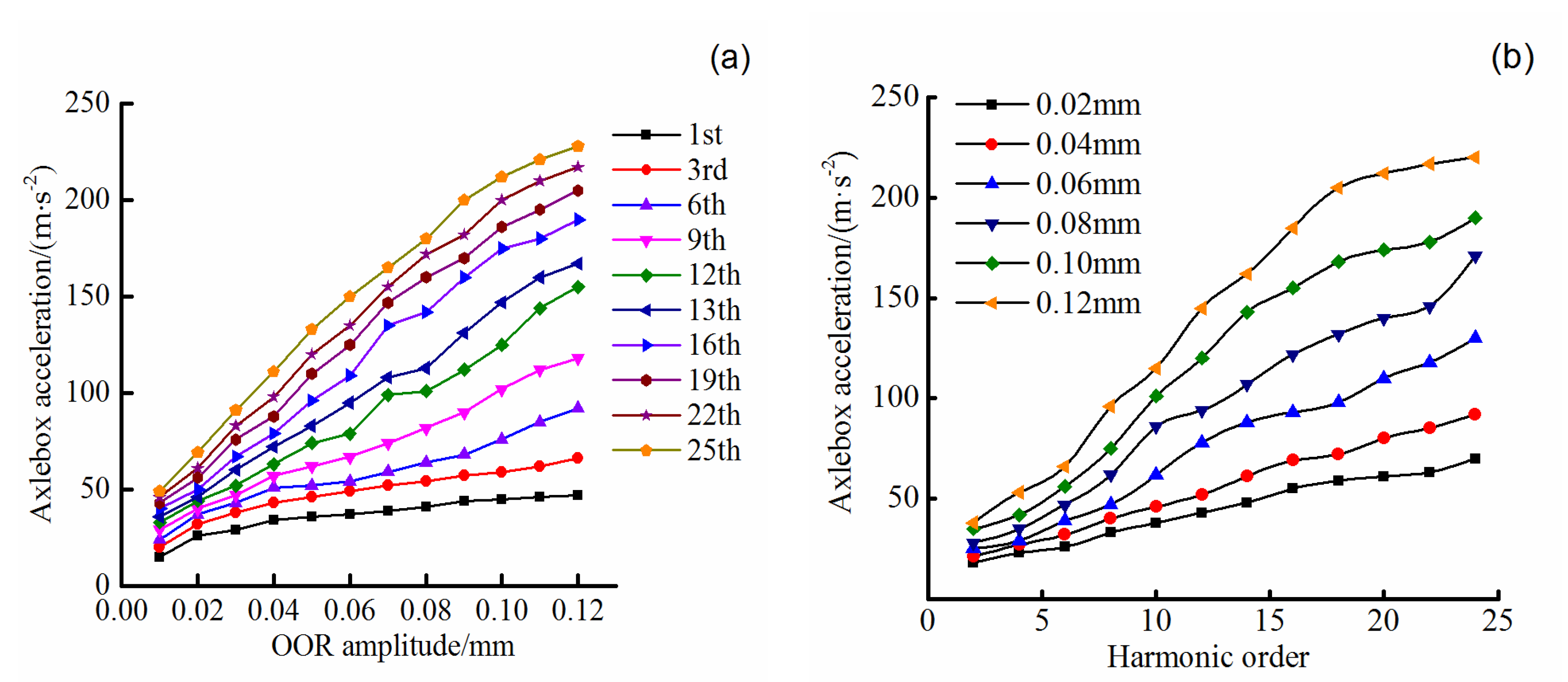
Figure 4 shows the time dependence of the vertical axle-box acceleration caused by wheel polygons of various harmonic orders and OOR amplitudes at a vehicle speed of 350 km·h−1. The harmonic orders of the polygonal wheels range from 1 and 25 (i.e., the polygonized wheels have 1 to 25 wavelengths around the circumference of the wheel). The OOR amplitudes range from 0.01 mm to 0.12 mm [27].
Figure 4a shows that the axle-box acceleration increases approximately linearly with OOR amplitude, with the slope for the highest-order polygonized wheel being several times greater than that for the lowest-order polygonized wheel. Table 2 shows the increase of axle-box acceleration per unit OOR amplitude (m·s−2·mm−1) for the first 25 orders of polygonized wheels. For example, when the velocity is 200 km·h−1, the growth in axle-box acceleration per unit OOR amplitude for the 25th-order polygonized wheel is 1421 m·s−2·mm−1, which is 7.2 times the growth per unit OOR amplitude for a 4th-order polygonized wheel. The growth rate increases gradually as the speed increases, reaching 285 m·s−2·mm−1 and 2115 m·s−2·mm−1 for the 4th and 25th orders, respectively, at a speed of 350 km·h1, which is 1.44 and 1.49 times greater than at 200 km·h1. When the vehicle speed is 350 km·h1, the growth per unit OOR amplitude of the axle-box acceleration with OOR amplitude for the 23rd-order polygonized wheels is 2034 m·s−2·mm−1, which is 4.9 times that for a 6th-order polygonized wheel. Thus, high-order polygonized wheels more strongly affect the axle-box vibration than do low-order polygonized wheels.
Figure 4b shows that the axle-box acceleration increases with increasing harmonic order and that the growth per harmonic order (m·s−2) increases substantially with increasing OOR amplitude. Table 3 lists the growth per harmonic order of axle-box acceleration for different OOR amplitudes. These results reveal that, for anOOR amplitude in the range 0.01 to 0.12 mm, the growth per harmonic order increases from 0.38 to 6.12 m·s−2, at 200 km·h−1, and from 1.05 to 10.22 m·s−2 at 350 km·h−1. It’s concluded that the growth per harmonic order of axle-box acceleration due to polygonized wheels increases gradually with increasing velocity at all OOR amplitudes.
The above analysis indicates that the axle-box vibrations caused by polygonized wheels are almost the largest in the entire vehicle system, a result attributed to the axle-box being directly connected without damping to the axle through a bearing. On Chinese high-speed trains, the axle-box and its related parts commonly suffer from vibration fatigue, which destroys end covers and loosens bolts.

4.1.2. Effect of Vehicle Speed

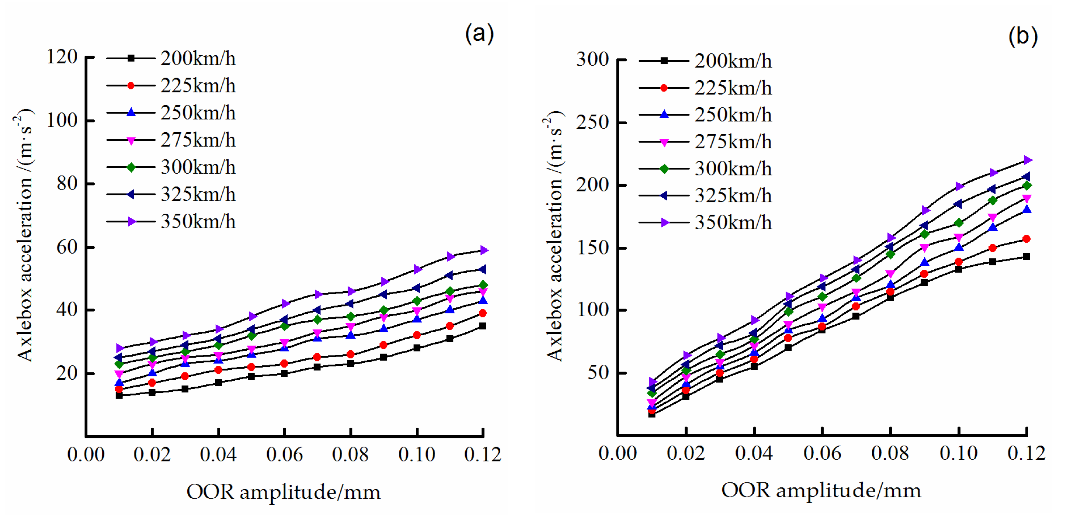
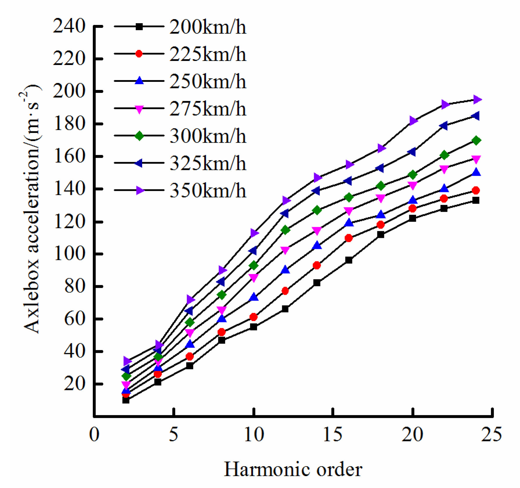
Figure 5 shows the maximum vertical axle-box accelerations as a function of OOR amplitude for a polygonal wheel with four waves and with 24 waves around its circumference and for train speeds from 200 to 350 km·h−1. Figure 6 shows the calculated axle-box acceleration as a function of harmonic order of polygonized wheel and for different vehicle speeds and an OOR amplitude of 0.10 mm.
Figure 5 shows that the growth per unit OOR amplitude of the vertical axle-box acceleration increases monotonically with vehicle speed. The calculated results shown in Figure 6 indicate that the maximum vertical axle-box acceleration is linear in harmonic order of the polygonal wheel and that this growth rate also increases with increasing train speed. However, the harmonic order has much less effect on the growth rate than does the OOR amplitude. At high speeds, the OOR amplitude of polygonal wheels is what most affects the axle-box acceleration.

4.2. Time-Frequency Analysis of Axle-Box Accelerations based on EEMD and WVD

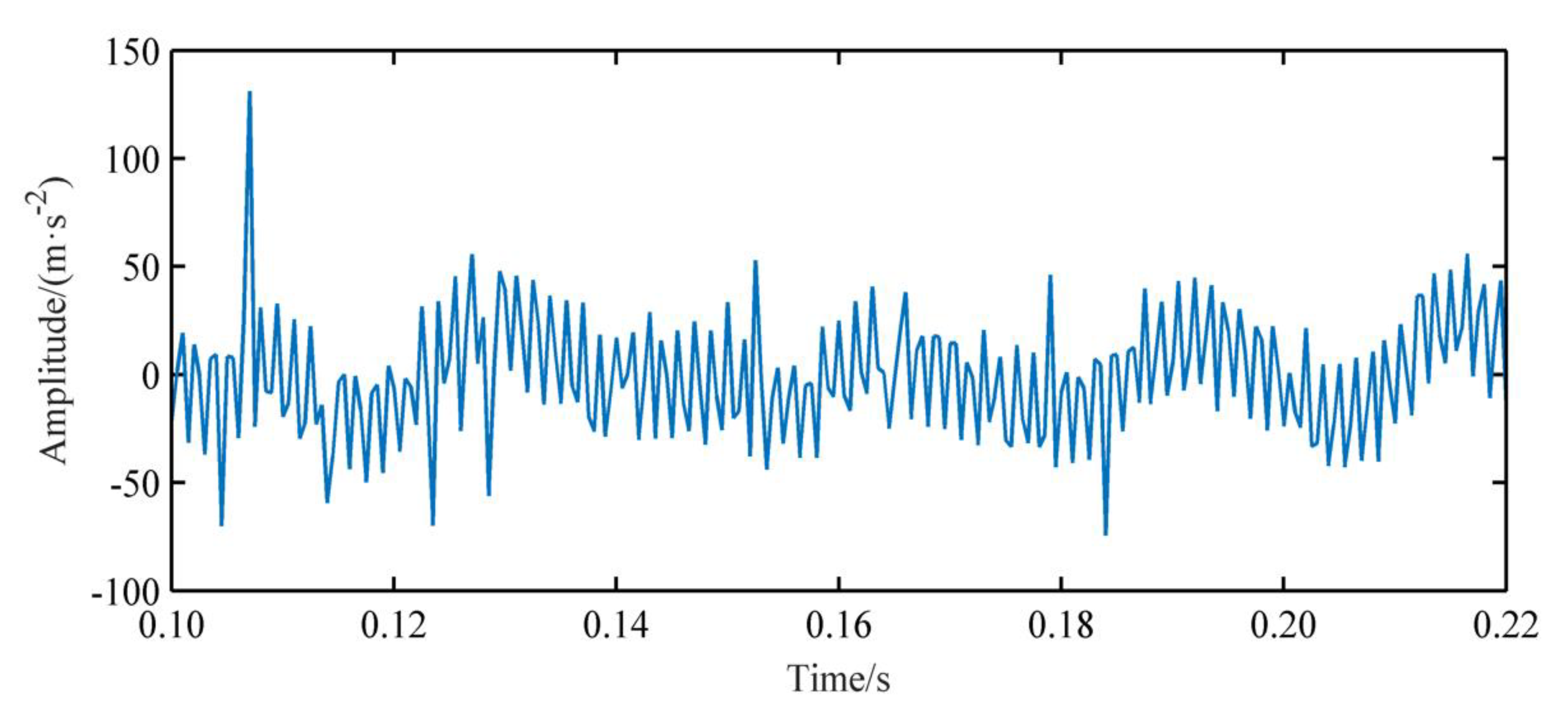
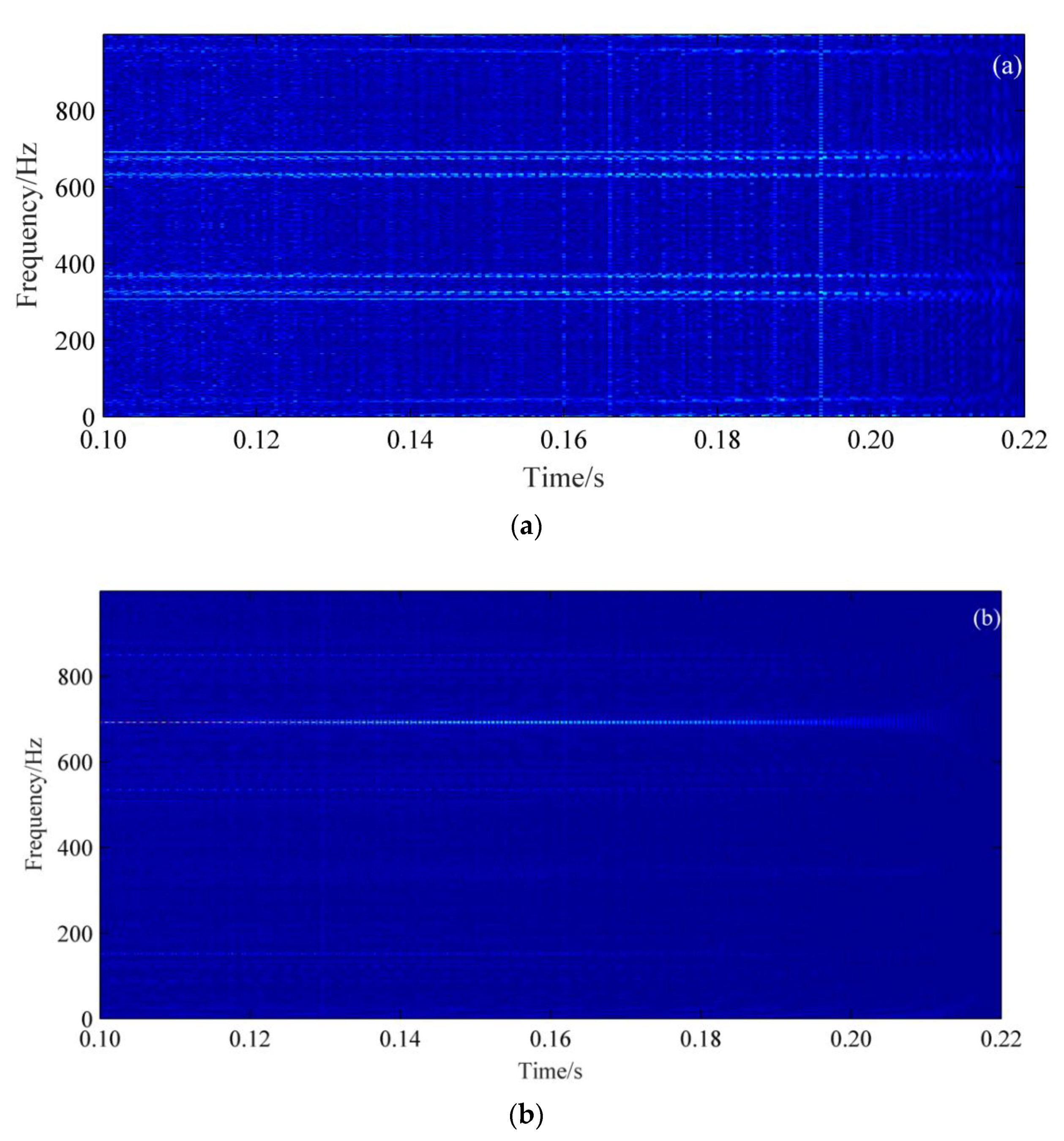
In this section are presented some results of the calculated axle-box acceleration analyzed by using the EEMD-WVD combined method described in Section 3.2, and comparison with the results calculated from WVD time-frequency representation. Figure 7 shows the time domain acceleration of the axle-box induced by a 24th-order wheel polygon with OOR amplitude of 0.02mmand a train speed of 300 km·h−1. Figure 8 shows the time-frequency spectrograms of the acceleration. The result of the WVD time-frequency analysis in Figure 8a reveals a clear horizontal band at about 690 Hz, which corresponds to the theoretical characteristic frequency of 691.9 Hz caused by the 24th-order polygonized wheel, as per the wavelength-fixing mechanism f = v / λ = n v / 2 π R = 24 × ( 300 / 3600 ) / ( 2 π × 460 ) = 691.9 Hz . However, unwarranted characteristic information also appears at other frequencies, which is due to the WVD crossterm and leads to an incorrect estimation. Figure 8b shows the time-frequency analytic spectrogram produced by the EEMD-WVD combined method. The most prominent characteristic frequency is again at 690 Hz, which represents information about abnormal vibration caused by the 24th-order wheel polygon. Furthermore, no other noticeable characteristic frequencies appear, unlike in Figure 8a. These analytic results show that the EEMD-WVD combined method suppresses the crossterm of the WVD but does not reduce the time-frequency resolution.
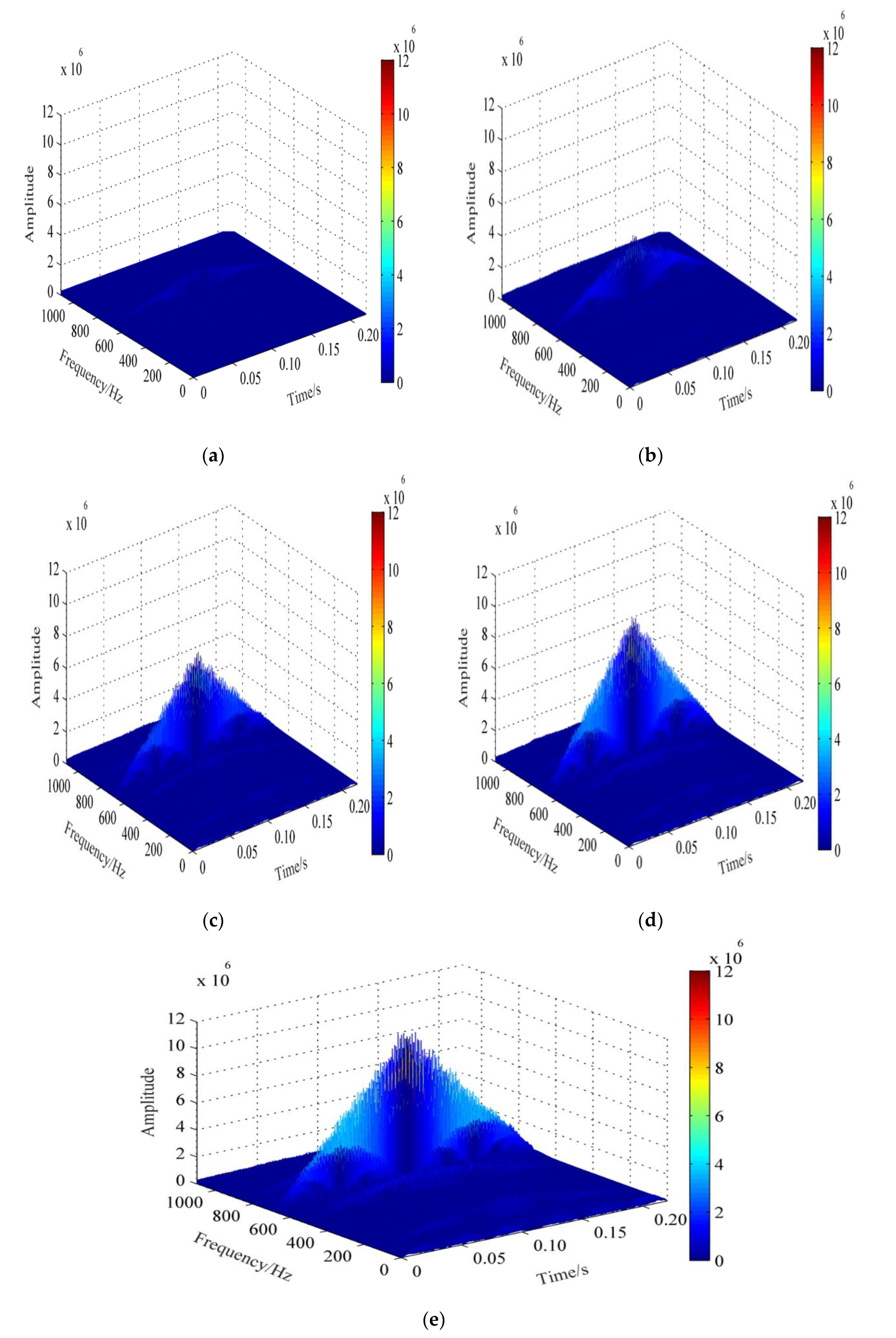
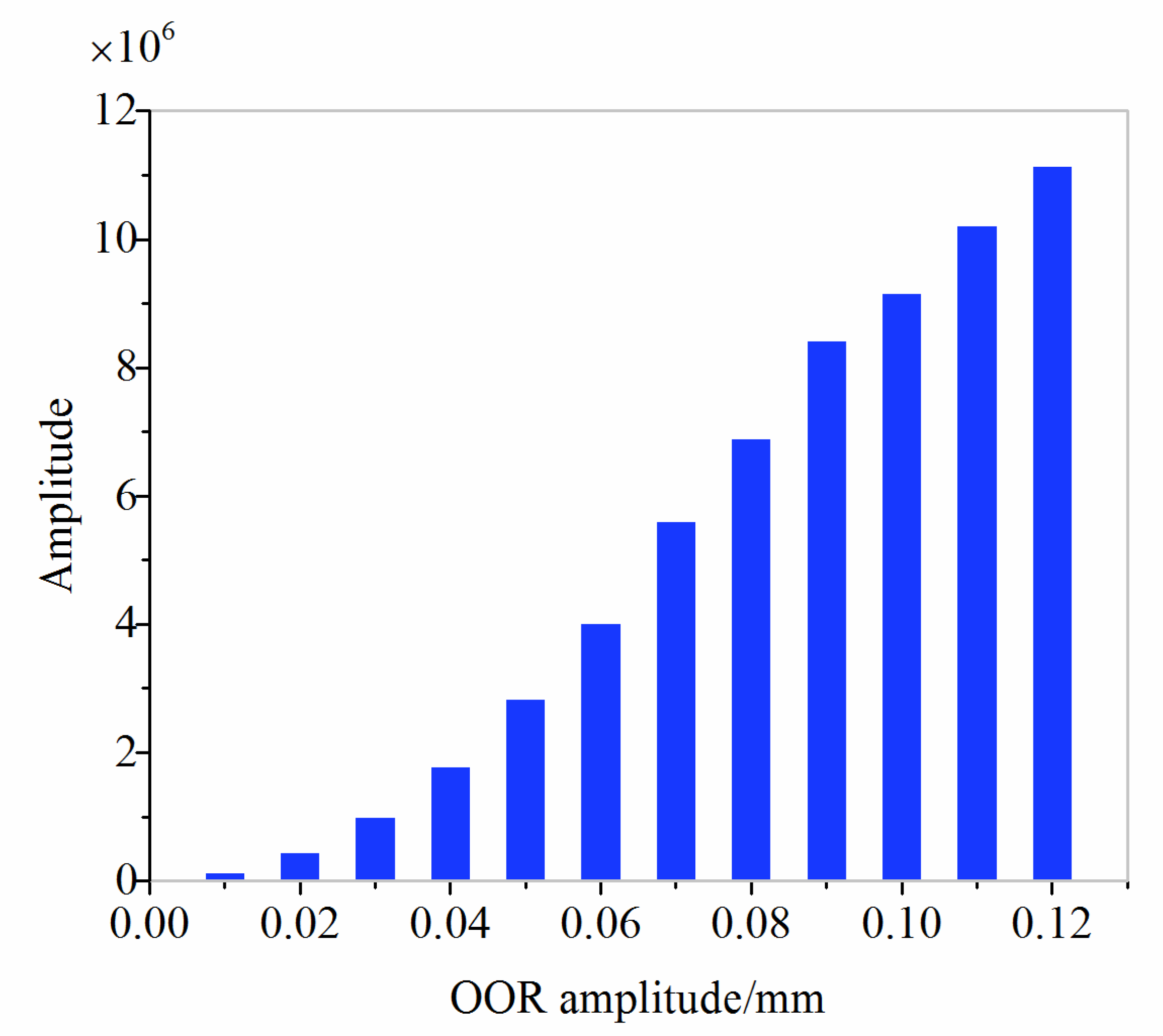
Figure 9 shows partial EEMD-WVD time-frequency-energy spectrograms of calculated axle-box acceleration caused by a 24th-order wheel polygon with OOR amplitudes varying from 0.01 to 0.12 mm. Note that the largest-power amplitudes in the spectrograms appear around 690 Hz, produced by the 24th-order wheel polygons. The frequency band at zero amplitude is narrow (690–700 Hz), which reflects a high frequency resolution. In addition, the peak amplitude (i.e., peak acceleration) of the simulated axle-box increases with increasing OOR amplitude (see Figure 10). These results imply that the presence of wheel polygons is clearly reflected in the spectrogram as a narrow band whose frequency depends on the harmonic order of the polygonized wheels and on the train speed. Furthermore, the peak amplitudes of the EEMD-WVD time-frequency-energy spectrogram are approximately linear in the OOR amplitude of the polygonized wheels. Thus, given the power amplitude of the axle-box acceleration, the train speed, and the harmonic order, the OOR amplitude of a polygonized wheel can be determined.

4.3. Comparision with Other Author Results

To verify the validity of the joint time-frequency analysis method, we used the proposed EEMD-WVD combined method to obtain the time-frequency characterization of vertical axle-box acceleration caused by areal polygonized wheel, as reported in [27]. The results (Figure 11a) reveal three thin horizontal lines in the spectrogram at the characteristic frequencies of 31, 710, and 740 Hz. Furthermore, axle-box vibration caused by a random polygonal wheel is also reflected in the time-frequency-energy spectrogram (Figure 11b), with the highest amplitude occurring around 740 Hz, the second highest occurring around 710 Hz, and the third highest occurring around 31 Hz. These results imply that the random polygonized wheel is dominated by harmonics 1, 23, and 24 around the wheel circumference, which is consistent with the field measurements reported in [27].
As mentioned above, Liet al. [18] based their research on detecting railway out-of-round wheel defects on the Hilbert-Huang transform (HHT). However, the HHT cannot assess the severity of wheel defects. The analytic results presented herein illustrate that EEMD-WVD allows us to detect wheel polygons not only by suppressing the WVD crossterms but also by retaining the time-frequency concentration and resolution.

4.4. Limitation and Futherwork

Although the numerical simulation has been performed considering the presence of track irregularity PSD of Chinese high-speed railway, there are many other nonlinear factors influencing the calculated axle-box acceleration responses, such as parameters of primary and secondary suspension systems, the stiffness and viscous damping parameters of the ballastless track model, and others. In this regard, experimental tests are under the plan to carry out on a real track, which allows considering the non-linearity of the vehicle-track coupled system and the environmental influences that cannot be easily predicted in the modeling process.
Future work will involve measurements in the laboratory and on a running train to prove the effectiveness of the proposed wheel-polygon detection method based on axle-box vibration. This will be followed by the design and development of a real-time system to monitor the development of wheel polygons.

5. Conclusions

This paper proposes the use of axle-box acceleration to detect railway-wheel polygons of high-speed trains. A dynamics model of a vehicle-track rigid-flexible coupled system was designed to capture the dynamic features of axle-box acceleration associated with polygonized wheels. The time-frequency representation of axle-box accelerations obtained by using the EEMD-WVD combined method clearly reveals the presence of polygonized wheels. The main conclusions are as follows:
(1)
The quantitative relationship between the characteristics of axle-box acceleration and wheel polygon defects is determined based on a parameter-lumped simple wheel-track model that accounts for wheel out-of-roundness. The frequency of the axle-box acceleration coincides with the characteristic frequency of polygonized wheels, which underpins the detection of wheel polygon defects based on axle-box vibration.
(2)
A dynamic model of a vehicle-track coupled system with flexible wheelsets and tracks is presented to determine the relationship between wheel polygon defects and axle-box acceleration. The results indicate that the maximum amplitude of the vertical axle-box acceleration is linear in both the harmonic order and in OOR amplitude of the polygonal wheel. Furthermore, the growth rate of acceleration increases monotonically with vehicle speed.
(3)
The EEMD-WVD combined method is used to make a time-frequency analysis of the axle-box acceleration. The frequency and corresponding amplitude of axle-box acceleration are quantitatively related to wheel polygon defects. It’s concluded that EEMD-WVD can be applied for wheel polygons detection and severity assessment.
(4)
The analysis shows that axle-box acceleration measurements can be used to detect and assess polygon wheels. When the characteristic frequency f1 ofaxle-box acceleration and the maxima magnitude aaxlebox at a given train speed v1 are determined, the wheel polygonal defects can be detected, provided f1 does not coincide with the axle-box vibration frequency f2 excited by round wheels. If f1f2, the harmonic order n of the polygon wheel can be determined by comparing f1 with the characteristic frequencies corresponding to the first 25 harmonics of a polygon wheel at the train speed v1.Based on the peak amplitude and the frequency of axle-box acceleration from the joint time-frequency analysis, the degradation due to wheel polygon defects can be evaluated.

Author Contributions

Conceptualization, Y.S.; Formal analysis, L.L.; Writing—review & editing, Y.D. and B.S.; funding acquisition, Y.S. All authors have read and agreed to the published version of the manuscript.

Funding

This research was funded by National Natural Science Foundation of China, grant number11372199, Natural Science Foundation of Hebei Province, grant number E2019210152, and China Postdoctoral Science Foundation Funded Project, grant number 2018M643521.

Acknowledgments

We acknowledge TopEdit LLC for the linguistic editing and proofreading during the preparation of this manuscript.

Conflicts of Interest

The authors declare no conflict of interest.

References

  1. Ahlbeck, D.R. A study of dynamic impact load effects due to railroad wheel profile roughness. Veh. Syst. Dyn. 1988, 17, 13–16. [Google Scholar] [CrossRef]
  2. Liu, J.; Han, J.; Xiao, X.B.; Liu, X.L.; Jin, X.S.; Wang, P. Influence of wheel non-circular wear on axle box cover abnormal vibration in high–speed train. Chin. J. Mech. Eng. 2017, 53, 98–105. [Google Scholar] [CrossRef]
  3. Zhang, F.B.; Wu, P.B.; Wu, X.W. Effects of wheel polygonalization on axle box for high speed train. Zhendong Ceshi Yu Zhenduan 2018, 38, 1063–1068. [Google Scholar]
  4. Johansson, A.; Andersson, C. Out–of–round railway wheels—A study of wheel polygonalization through simulation of three–dimensional wheel–rail interaction and wear. Veh. Syst. Dyn. 2005, 43, 539–559. [Google Scholar] [CrossRef]
  5. Lutzenberge, S.; Wu, Q.L. Condition based maintenance of railway wheel treads and identification of the relevant mechanism with monitoring. In Proceedings of the 18th International Wheelset Congress, Chengdu, China, 7–10 November 2016. [Google Scholar]
  6. Remington, P.; Webb, J. Estimation of wheel/rail interaction forces in the contact area due to roughness. J. Sound Vib. 1996, 1, 83–102. [Google Scholar] [CrossRef]
  7. Attivissimo, F.; Danese, A.; Giaquinto, N.; Sforza, P. A railway measurement system to evaluate the wheel–rail interaction quality. IEEE Trans. Instru. Meas. 2007, 5, 1583–1589. [Google Scholar] [CrossRef]
  8. Stratman, B.; Liu, Y.; Mahadevan, S. Structural health monitoring of railroad wheels using wheel impact load detectors. J. Fail. Anal. Prev. 2007, 3, 218–225. [Google Scholar] [CrossRef]
  9. Lee, M.L.; Chiu, W.K. A comparative study on impact force prediction on a railway track–like structure. Struct. Health. Monit. 2005, 4, 355–376. [Google Scholar] [CrossRef]
  10. Wei, C.; Xin, Q.; Chung, W.H.; Liu, S.-Y.; Tam, H.-Y.; Ho, S.L. Real–time train wheel condition monitoring by Fiber Bragg Grating sensors. Int. J. Distrib. Sens. Netw. 2011, 8, 409048. [Google Scholar] [CrossRef]
  11. Papaelias, M.; Huang, Z.; Amini, A.; Vallely, P.; Day, N.; Sharma, R.; Kerkyras, Y.; Kerkyras, S. Advanced wayside condition monitoring of rolling stock wheelsets. In Proceedings of the 11th ECNDT, Prague, Czech, 6–10 October 2014. [Google Scholar]
  12. Guagliano, M.; Pau, M. An experimental–numerical approach for the analysis of internally cracked railway wheels. Wear 2008, 9–10, 1387–1395. [Google Scholar] [CrossRef]
  13. Yang, K.; Gao, X.R.; Dai, L.X. Research on the principle of railway wheel out-of-roundness on-line dynamic detecting system based on laser measurement. In Proceedings of the 2014 IEEE 11th Far East Forum on Nondestructive Evaluation/Testing: New Technology and Application, Chengdu, China, 20–23 June 2014. [Google Scholar]
  14. Coudert, F.; Sunaga, Y.; Takegami, K. Use of axle box acceleration to detect track and rail irregularities. WCRR 1999, 7, 1–7. [Google Scholar]
  15. Tanaka, H.; Furukawa, A. The estimation method of wheel load and lateral force using the axlebox acceleration. In Proceedings of the World Congress of Rail Research, Seoul, Korea, 22 May 2008. [Google Scholar]
  16. Molodova, M.; Li, Z.; Dollevoet, R. Axle box acceleration: Measurement and simulation for detection of short track defects. Wear 2011, 271, 349–356. [Google Scholar] [CrossRef]
  17. Salvador, P.; Naranjo, V.; Insa, R.; Teixeira, P. Axlebox accelerations: Their acquisition and time–frequency characterisation for railway track monitoring purposes. Meas. J. Int. Meas. Confed. 2016, 82, 301–312. [Google Scholar] [CrossRef] [Green Version]
  18. Li, Y.F.; Liu, J.X.; Li, Z.J. The fault diagnosis method of railway out-of-round wheels using Hilbert–Huang transform. ZhendongCeshi Yu Zhenduan 2016, 36, 734–739. [Google Scholar]
  19. Caprioli, A.; Cigada, A.; Raveglia, D. Rail inspection in track maintenance: A benchmark between the wavelet approach and the more conventional Fourier analysis. Mech. Syst. Signal Process. 2007, 2, 631–652. [Google Scholar] [CrossRef]
  20. Jia, S.; Dhanasekar, M. Detection of rail wheel flats using wavelet approaches. Struct. Health Monit. 2007, 2, 121–131. [Google Scholar] [CrossRef]
  21. Shin, Y.S.; Jeon, J.J. Pseudo Wigner–Ville time-frequency distribution and its application to machinery condition monitoring. Shock Vib. 1993, 1, 65–76. [Google Scholar] [CrossRef]
  22. Liang, B.; Iwnicki, S.; Ball, A.; Young, A.E. Adaptive noise cancelling and time–frequency techniques for rail surface defect detection. Mech. Syst. Signal Process. 2015, 54, 41–51. [Google Scholar] [CrossRef] [Green Version]
  23. Wang, X.L. Detection of Out–Of–Roundness Wheels of Urban Rail Train Based on Improved Wigner–Ville Distribution. Master’s Thesis, Nanjing University of Science & Technology, Nanjing, China, 2017. [Google Scholar]
  24. Xu, P.; Cai, C.B. Dynamic analysis of longitudinally connected ballastless track on earth subgrade. J. SouthwestJiaotong Univ. 2011, 46, 189–194. [Google Scholar]
  25. Ripke, B.; Knothe, K. Simulation of high frequency vehicle—Track interactions. Veh. Syst. Dyn. 1995, 24, 72–85. [Google Scholar] [CrossRef]
  26. Song, Y.; Du, Y.; Zhang, X.; Sun, B. Evaluating the effect of wheel polygons on dynamic track performance in high–speed railway systems using co–simulation analysis. Appl. Sci. 2019, 9, 4165. [Google Scholar] [CrossRef] [Green Version]
  27. Chen, M.; Zhai, W.M.; Ge, X.; Sun, Y. Analysis of wheel-rail dynamic characteristics due to polygonal wheel passing through rail weld zone in high-speedrailways. Chin. Sci. Bull. 2019, 64, 2573–2582. (In Chinese) [Google Scholar] [CrossRef] [Green Version]
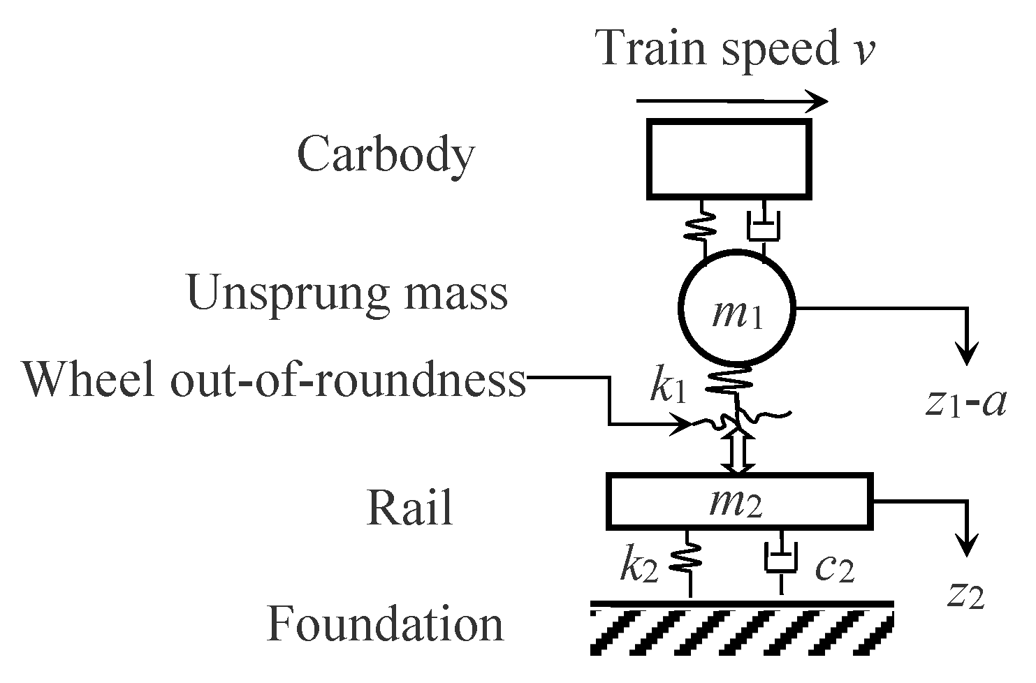
Figure 1. Parameter-lumped simple wheel-track model after introducing wheel out-of-roundness.
Applsci 10 01613 g001
Figure 2. Vehicle-track rigid-flexible coupling dynamics system for UM-ANSYS simulation:(a) Mechanical model of train-vehicle coupling system; (b) Enlarged view of flexible wheelsets and tracks.
Applsci 10 01613 g002
Figure 3. Flow chart showing algorithm for joint time-frequency analysis based on Ensemble Empirical Mode Decomposition (EEMD) and Wigner-Ville distribution (WVD).
Applsci 10 01613 g003
Figure 4. Vertical acceleration of axle-box as a function of (a) out-of-roundness (OOR) amplitude and (b) harmonic order of polygonized wheel at 350 km·h−1.
Applsci 10 01613 g004
Figure 5. Vertical axle-box acceleration as a function of OOR amplitude at different speeds for (a) a 4th-order polygonized wheel and (b) a 24th-order polygonized wheel.
Applsci 10 01613 g005
Figure 6. Axle-box acceleration as a function of harmonic order of polygonized wheel (i.e., the number of wavelengths around the wheel) for several train speeds.
Applsci 10 01613 g006
Figure 7. Time-domain response of vertical axle-box acceleration due to 24th-order wheel polygon with OOR amplitude of 0.02mm at 300 km·h−1.
Applsci 10 01613 g007
Figure 8. Spectrogram corresponding to the signal shown in Figure 7: (a) WVD time-frequency analytic spectrogram; (b) EEMD-WVD time-frequency analytic spectrogram.
Applsci 10 01613 g008
Figure 9. EEMD-WVD time-frequency-energy spectrograms corresponding to the axle-box acceleration caused by 24th-order polygonized wheels and for different OOR amplitudes: (a) OOR amplitude of0.04 mm; (b) OOR amplitude of0.06 mm; (c) OOR amplitude of0.08 mm; (d) OOR amplitude of0.10 mm; (e) OOR amplitude of0.12 mm.
Applsci 10 01613 g009
Figure 10. Peak power amplitude of axle-box acceleration due to 24th-order polygonal wheels as a function of OOR amplitude.
Applsci 10 01613 g010
Figure 11. Results of EEMD-WVD analysis of axle-box acceleration caused by real polygonized wheels [27]: (a) time-frequency spectrogram; (b) time-frequency-energy spectrogram.
Applsci 10 01613 g011
Table 1. Parameters of vehicle and track systems.
ComponentParameterValue
CarbodyMass (kg)4.0× 10⁴
Moments of pitch inertia (kg·m2)2.0× 10⁶
Moments of roll inertia (kg·m2)1.0× 10⁵
Moments of yaw inertia (kg·m2)2.0× 10⁶
BogieMass (kg)2.0× 10³
Moments of pitch inertia (kg·m2)2.5× 10³
Moments of roll inertia (kg·m2)1.5× 10³
Moments of yaw inertia (kg·m2)3.5× 10³
WheelsetMass (kg)1.5× 10³
Moments of pitch inertia (kg·m2)120
Moments of roll inertia (kg·m2)800
Moments of yaw inertia (kg·m2)800
nominal rolling radius (m)0.46
AxleboxMass (kg)50.0
Moments of pitch inertia (kg·m2)5.0
Moments of roll inertia (kg·m2)1.0
Moments of yaw inertia (kg·m2)5.0
CHN60 railElastic modulus (N·m−2)2.1 × 10¹¹
Poisson ratio0.3
Density(kg·m−3)7800
Rail fasteningsElastic stiffness(MN·m−1)50
Damping coefficient (kN·s·m−1)60
Longitudinal spacing(m)0.65
Concrete slab layerElastic modulus(N·m−2)3.9×10¹⁰
Poisson ratio0.2
Length × width × thickness (m)6.45 × 2.55 × 0.20
Density(kg·m−3)2500
CA mortar layerElastic modulus(N·m−2)7.0×10⁹
Poisson ratio0.167
Thickness(m)0.03
Density(kg·m−3)2590
FoundationElastic modulus(N·m−2)5.0×10⁹
Poisson ratio0.2
Width × thickness(m)3.25 × 0.3
Density(kg·m−3)2500
Table 2. Growth per unit OOR amplitude of axle-box acceleration due to polygonized wheels, in m·s−2·mm−1.
Train Speed(km·h−1)
200225250275300325350
Harmonic OrderGrowth Rate (m·s−2·mm−1)
1108122156170192233242
2123155171184224248261
3173199214225246255275
4198206216229234267285
5205221242256.268294327
6213222266301315336415
7251258298336355389452
8295310316378406446510
9324337340434446480542
10349398394471465556642
11374438456519599675757
12426472493651749788936
134725195837088729361100
1449156663580495810911257
15520645793904100912151447
16553672883940102012641452
175806988981063109012891475
186267559381196121113451602
1974487010711296130214681699
20829101212401450148316191832
21996118013501498151116921899
221023135414671611168517211975
231155141315561756179218212034
241302152216211796180318752089
251421161117431882190119682115
Table 3. Growth per harmonic order of axle-box acceleration due to polygonized wheels, in m·s−2·order−1.
Speed(km·h−1)
200225250275300325350
OOR Amplitude (mm)Growth Rate (m·s−2)
0.010.380.450.620.750.970.991.05
0.020.631.151.311.451.581.641.97
0.031.511.751.821.972.172.643.73
0.042.012.432.552.753.123.204.14
0.052.943.123.523.784.404.985.28
0.063.223.674.495.285.805.896.24
0.074.064.384.875.586.346.927.13
0.084.434.585.255.906.607.057.78
0.095.015.736.297.087.848.208.68
0.105.456.256.987.558.118.869.35
0.115.846.777.117.898.769.139.87
0.126.127.317.948.349.159.9410.22