Article

Model-Based Virtual Components in Event-Based Controls: Linking the FMI and IEC 61499

1
Center for Energy, Austrian Institute of Technology, 1210 Vienna, Austria
2
Institute of Computer Engineering, Automation Systems Group, TU Wien, 1040 Vienna, Austria
3
Ormazabal Corporate Technology, 48340 Amorebieta-Etxano, Bizkaia, Spain
*
Author to whom correspondence should be addressed.
Appl. Sci. 2020, 10(5), 1611; https://doi.org/10.3390/app10051611
Submission received: 30 January 2020 / Revised: 24 February 2020 / Accepted: 24 February 2020 / Published: 28 February 2020
(This article belongs to the Special Issue Simulation-Based Validation and Design of Smart Grids)

Abstract

:
Various development and validation methods for cyber-physical systems such as Controller-Hardware-in-the-Loop (C-HIL) testing strongly benefit from a seamless integration of (hardware) prototypes and simulation models. It has been often demonstrated that linking discrete event-based control systems and hybrid plant models can advance the quality of control implementations. Nevertheless, high manual coupling efforts and sometimes spurious simulation artifacts such as glitches and deviations are observed frequently. This work specifically addresses these two issues by presenting a generic, standard-based infrastructure referred to as virtual component, which enables the efficient coupling of simulation models and automation systems. A novel soft real-time coupling algorithm featuring event-accurate synchronization by extrapolating future model states is outlined. Based on considered standards for model exchange (FMI) and controls (IEC 61499), important properties such as real-time capabilities are derived and experimentally validated. Evaluation demonstrates that virtual components support engineers in efficiently creating C-HIL setups and that the novel algorithm can feature accurate synchronization when conventional approaches fail.

1. Introduction

The complexity of instances of cyber-physical systems, like smart grids, calls for mature testing and validation methods in order to ensure correct operation in safety-critical situations [1]. In this context, model-based techniques allow representing parts of the overall system as virtual components and to simulate their dynamic behavior using numerical models, e.g., for evaluating control algorithms based on a virtual model of the physical system [2]. Such applications require the coupling of (time-continuous) simulation models with automation infrastructure, forming hybrid discrete/continuous systems. Integration of discrete and continuous dynamics remains a challenging task [3], due to the need for non-trivial time synchronization in combination with (distributed) event handling and accuracy requirements. Hardware-in-the-Loop (HIL) simulation, where some parts of the control loop are physical hardware, imposes even stricter requirements, like real-time capabilities. The accuracy of HIL setups strongly depends on the timing and synchronization properties, e.g., to avoid instabilities [4].
Typically, simulation models and automation systems are coupled using tool-specific and/or custom-built interfaces, which require significant development effort and offer little reusability [5]. In contrast, interfaces based on established technology standards covering a broader variety of simulation models and tools offer the ability to develop more generic virtual component interfaces that are reusable across different setups.
In this work, a concept for a generic virtual component for bridging the gap between the automation systems and simulation domain is devised. This generic virtual component is based on established standards from each domain, in particular the IEC 61499 and Functional Mock-up Interface (FMI) standard, and implements two different approaches for time synchronization and event mapping.
The article is structured as follows: Section 2 briefly describes the state-of-the-art, and Section 3 introduces the concept of generic virtual components in detail. An experimental evaluation of the studied concepts is presented in Section 4, and concluding remarks are given in Section 5.

2. Related Work

Various efforts in combining simulation models and tools, both on a per-tool basis and via dedicated standards, have already been conducted [2,6,7,8,9,10,11]. In general, standard-based couplings reduce the effort of tool-specific links and support a generic method beyond a specific use case [6]. Nevertheless, special attention has to be put on accurately mapping underlying simulation methods to standard-based simulation interfaces [7,8,10,11].

2.1. Functional Mock-Up Interface

One standardized numeric representation of simulation models is given by the FMI standard for Model Exchange [6,12,13]. At the time of writing, two versions, 1.0 and 2.0, of the FMI have been released. The second FMI version introduces several optional capabilities such as persisting the state of a model. Each numerical model is encapsulated into a single file, which is referred to as Functional Mock-up Unit (FMU), and can be instantiated and accessed by other tools, for instance to create a comprehensive simulation with models from various sources. The FMU itself contains a static XML-based model description and a set of C functions that implement the dynamic behavior of the model, represented by a set of Ordinary Differential Equations (ODEs) and discontinuities including discrete changes, called events [12,13]. Equations are defined in terms of C functions and require an external numerical solver to compute the results of a simulation. An FMU may either contain a compiled platform-specific binary executable of the C functions or the source code itself.
In order to create a generic virtual component that connects simulation with automation infrastructure, one needs to couple the continuous or hybrid FMI-based component model and the surrounding discretized system. Although the FMI does not focus on purely discrete systems, several authors have successfully described the integration of FMUs, and hybrid models in general, into discrete event-based simulations [7,8,14]. Eker et al. presented a structured approach for coupling heterogeneous models, such as continuous-time and discrete event-based models, into a joint simulation that forms a tree of locally homogeneous submodels [14].
A predictive approach for integrating FMUs into discrete event-based simulations was proposed in [7,8] and implemented as an external library called FMI++. The approach allows bidirectionally synchronizing the operation according to the timing of scheduled events.

2.2. Distributed Control Systems Using IEC 61499

The concept of events to overcome a strictly periodic operation is also found in industrial control applications [15,16,17]. The IEC standard 61499 defines a system-level design language for distributed event-based control systems and has been successfully deployed in several industrial applications [18,19]. The scope of IEC 61499 is well beyond mere scheduling of control algorithms [15,16,17].
The standard defines several architectural entities, such as devices, potentially distributed applications, and Function Blocks (FBs). In general, control applications are composed of connected FBs that implement a certain operation and expose their functionality via dedicated in- and out-puts. An FB may provide event in- and out-puts that can be associated with data in- and out-puts, respectively. As soon as an event is encountered in one of the event inputs, the operation of the FB is triggered, data outputs may be updated, and output events can be fired. Some FB may additionally trigger output events without prior input events, e.g., in case some hardware inputs change or a timeout is reached.
Strasser et al. demonstrated that IEC 61499 is not limited to asynchronous control strategies, but can also be successfully used in synchronous closed-loop controls [19]. As such, the concept of event-based virtual components is also applicable in synchronous systems.
In the current IEC 61499 standard, it is not possible to express real-time semantics such as execution-time constraints [15,20]. To overcome these limitations, Lindgren et al. proposed backwards compatible real-time semantics and demonstrated its use in a response-time and CPU-time analysis [20]. Hence, it is possible to analyze the real-time behavior of IEC 61499-based controllers that access virtual components, but further information beyond the standard is needed.

2.3. Model-Based Control Engineering

Some efforts in coupling controllers and simulation models have already been presented [2,9,21]. In order to use tools not designed for hard real-time operation in real-time co-simulations, Zehetner et al. presented a co-simulation algorithm based on polynomial extrapolation to break closed loops between real-time and non-real-time facilities [22].
Several commercially available tools already claim to support HIL simulations and the FMI (for instance: TISC Suite, Simulation Workbench, Labcar-Operator, ControlBuild, CarMaker, Model.CONNECT). Many of these tools specifically focus on the automotive domain, but some tools already implement communication protocols from the automation domain or specifically target automation systems. Gunnarsson, Erwall, and Mårtensson conducted proof-of-concept experiments to test FMI support in B&R Automation Studio based on a reaction wheel pendulum [23,24]. A co-simulation in Automation Studio and a controller HIL simulation using two Programmable Logic Controllers (PLCs) revealed that, in principle, the HIL simulation was feasible and that the outcome was strongly influenced by the chosen cycle time.
Although some work in standard-based linking of automation and simulation tools has already been conducted, none of the reviewed approaches specifically focused on event-based controls for real-time applications. In particular, the application of predictive event synchronization in real-time control systems has not been analyzed in detail, yet. Preliminary work outlining predictive real-time event synchronization for automation systems has been presented in [25], but no closed-loop operation and only limited support for a best-effort operation could be achieved.

3. Generic Virtual Components

The demand for creating virtual mock-ups that efficiently emulate system components does not allow for time and cost intensive development efforts. A model needs to be transformed into virtual components as fast and seamlessly as possible to enable rapid development life cycles. A generic virtual component shortcuts the manual coupling effort by integrating the model into the surrounding automation system without the prior need for developing the appropriate interfaces or mock-up implementations.
Since generic virtual components are not limited to a particular model or automation system, a discussion needs to be based on general assumptions on the model and the automation system. In particular, the presented work assumes an FMI-compliant model to encode the component behavior and an IEC 61499-compliant automation system in which the virtual component is instantiated. Still, various levels of integration are conceivable, e.g., by transforming a component model into an IEC 61499-compliant description [26] or by accessing the component via a network connection [2,9].

3.1. System Model

A generic virtual component cannot rely on the system architecture of a particular plant or control system. On the contrary, a suitable abstract architecture needs to be found for further analysis. In order to feature a generalized discussion in the context of IEC 61499, it is assumed that:
  • the virtual component can be accessed via a dedicated FB,
  • communication is restricted to the occurrence of events,
  • each event e is triggered at a particular instant of time t ( e ) [27], and that
  • e holds a set of variables that are either sent to the virtual component or to the automation system.
Although a control algorithm may choose to alter a variable between two consecutive events, values are not communicated across FB boundaries. From an outside perspective, a continuous virtual component holds exposed values constant unless they are communicated via an event.
Still, the FMI-based representation of the virtual component needs to be mapped to a set of properly timed events. An abstract system model of a generic virtual component is presented in Figure 1, which defines the following major components:
  • Representational mapping: A generic virtual component has to map the hybrid representation defined by the FMI to discrete events that can be exchanged within the automation system. Such a mapping comprises the numerical computation of the state of the FMU based on its ODEs and the algorithm mapping possibly continuous in- and out-puts to discrete events e. The algorithm will be discussed in more detail in the following sections.
  • Time synchronization: Since IEC 61499 events do not include a notion of time, the current progress of simulation time has to be synchronized, e.g., to the clock of a controller. Synchronization may also influence the range of feasible approaches for representational mapping since such a projection may have to be conducted in real time.
  • Automation system interface: The actual integration of the virtual component into the automation system is implemented in the automation system interface, e.g., via a network connection. It is assumed that the automation system interface simply relays discrete events e without changing their abstract semantics.

3.2. Periodic Event Mapping

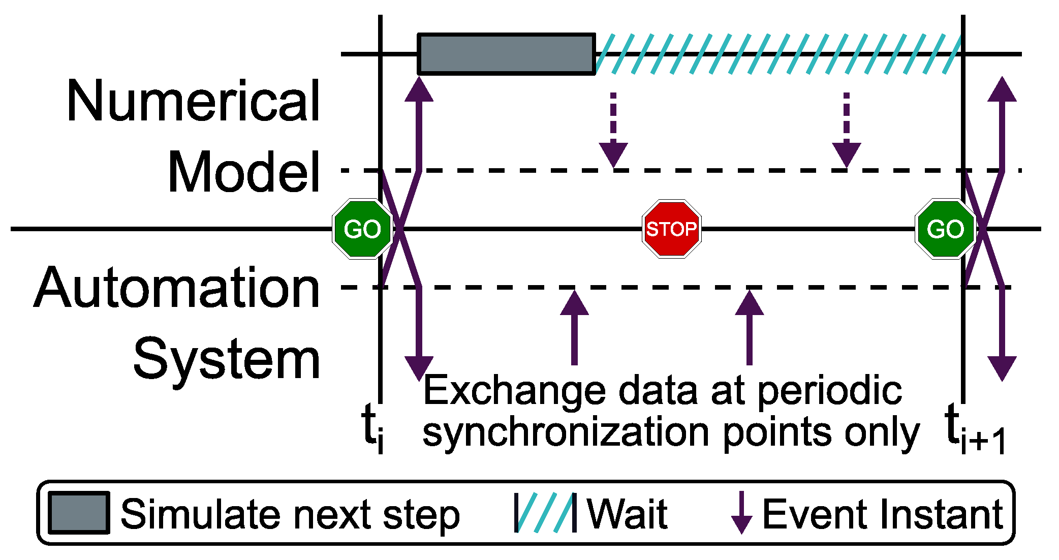
One commonly used approach for implementing the abstract representational mapping of Figure 1 is periodic synchronization. Thereby, data are periodically exchanged at discrete points in simulation time, t i = i · T a with T a R + and i N 0 , only. For each synchronization point, an event e i , t ( e i ) = t i , which covers the model outputs, is sent to the automation system. Between two consecutive synchronization points, the model is solved independently, and no data are exchanged. In case an event e j with t i < t ( e j ) < t i + 1 is triggered by the automation system, it has to be delayed until the next synchronization point t i + 1 . Likewise, any FMI event between synchronization points indicating a possible discontinuity cannot be directly transmitted because outputs are only sampled at the next synchronization point. Figure 2 illustrates the basic operation of the periodic approach.
Although a controller may maintain its own notion of time differently from real time (e.g., in the case of a purely virtual simulation), often the virtual component needs to run according to real time. To study the timing of virtual components in more detail, the progress function p k : R R is introduced, which maps the current instant of real time t to the current notion of (simulation) time of component k. For the automation system AS, simply a continuous clock is assumed and p AS ( t ) = t . For an FMU, p FMU ( t ) is controlled by the solver and may differ from the current instant of real time. Notably, p FMU ( t ) may not be continuous because the equations are solved in discrete steps. In order to allow a timely operation, all synchronization events e = e i have to be triggered in time, and the progress of every component k has to converge to:
t ( e ) = lim t t ( e ) p k ( t ) .
To guarantee a hard real-time operation with the idealized real-time condition (1), the Worst Case Execution Time (WCET) W sol of solving one step of size T a needs to be bound, and in conjunction with the communication WCET W co , the constraint W sol + W co < T a has to hold. W sol highly depends on the WCETs of the FMI functions, as well as the ODE solver and may not even exist. Additionally, an FMU may indicate an arbitrary number of FMI events n i at step i. When assuming that solving one continuous step is bound by W step , an event update by W upd , and managing the model in- and out-puts by W io , one can estimate W sol by:
W sol = ( n i + 1 ) · W step + ( n i + 2 ) · W upd + W io .
Note that the event update function has to be executed at the end of each continuous step and after external inputs are applied. Even if the solver and all FMI functions provide a bound WCET, the number of events n i within a single step needs to be bound as well.

3.3. Predictive Event Mapping

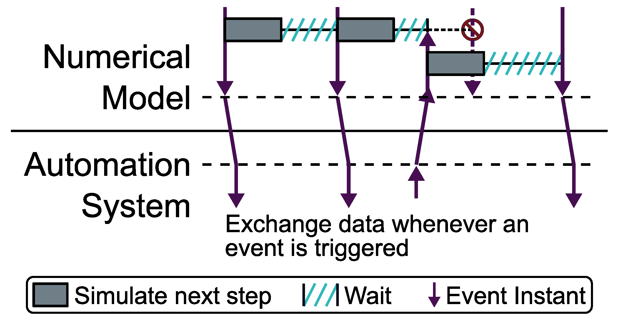
One major drawback of periodic event mapping is that instant changes in both the FMI model and the automation system cannot be directly communicated, but have to be delayed until the next communication point t i + 1 . Hence, the event mapping may be well-suited for periodic control and communication schemes, but hinders asynchronous integration of virtual components. In particular, for delay-sensitive applications, a considerable deviation may be introduced, and T a needs to be carefully chosen. The predictive approach proposed in [7,8] and illustrated in Figure 3 can be used to dynamically choose the next synchronization point and to reduce nominal delays. For predictive event mapping, FMI events and IEC 61499 events are directly mapped without introducing periodic synchronization events e i . Nevertheless, an FMU or the interface program may choose to trigger intermediate events to communicate altered continuous outputs.
To provide adaptive synchronization, the predictive approach solves the included FMU until the next communication need is encountered [7,8]. The prediction is conducted under the assumption that no external event that potentially changes inputs is scheduled. As soon as an external event is scheduled before the upcoming predicted event, the state of the model is reset to the time instant of the external event, the predicted event that was added to the event queue before is invalidated, and the prediction cycle starts anew. In order to aid resetting the FMU, multiple intermediate states that can be quickly recalled without repeating numerical integration are periodically stored.
While in non-real-time applications with revocable events, exact synchronization is feasible [7,8], special attention has to be placed on real-time operation. Again, precise real-time operation would be established if all FMI events e are triggered in time (1). Define f k ( e ) as the time when component k finishes processing the arbitrary event e, and assume that event e a 1 has to be processed just before the FMI event e a . To predict one event fully, including its associated values, and to advance the progress function p FMU ( t ) at the real time instant t to p FMU ( t ) = t ( e a ) , one needs to predict the upcoming event e a , call the FMI event update function, and manage the output calculation and transmission [25]. When assuming that predicting one event takes at most W pred and managing the model outputs has a WCET of W out , e a can be safely triggered in time if:
f FMU ( e a 1 ) + W pred + W upd + W out < t ( e a ) .
In general, IEC 61499 events e may be enqueued and processed out of time, i.e., f FMU ( e ) > t ( e ) . Consequently, the time from which on an FMI event e a is safely permitted depends on the type and time of previous events e b , t ( e b ) t ( e a ) . In order to reduce the event interdependency, one can assert that each event is immediately processed and that e a 1 is triggered in a timely manner, i.e., Equation (1) is satisfied for the event origin k [25]. First, let e a 1 be an event from the automation system and assume that processing e a 1 takes at most W a - upd . Consequently, (3) implies:
t ( e a 1 ) + W a - upd + W pred + W upd + W out < t ( e a ) .
Second, let e a 1 be an FMI event. By definition, processing e a 1 ends as soon as it is fully predicted and (3) implies (5) and (4), as well.
t ( e a 1 ) + W pred + W upd + W out < t ( e a )
To maintain the assertion of timed events e c from the automation system, e c must not be triggered unless the FMU has finished processing the previous event e c 1 and does not start to finalize the next predicted event e a by calling the update and output functions. According to the event mapping algorithm, each event triggers a new prediction, even if the next event is external. Similarly, e c can be safely triggered if (6) holds, and (7) is implied for both types of events when assuming a timely operation of e c 1 :
f FMU ( e c 1 ) + W pred t ( e c ) < t ( e a ) ( W upd + W out )
t ( e c 1 ) + W a - upd + W pred < t ( e c ) < t ( e a ) ( W upd + W out )
From the WCET analysis, it follows that for all types of events, there is a time frame in which they may safely occur. Nevertheless, in comparison to the periodic approach, not only the total number of events between two consecutive synchronization points, but also the distance between any two consecutive events has to be restricted, which particularly prevents models featuring feedthrough [25]. Still, predictive event mapping allows sampling and transmitting data values as soon as an event is triggered, even if a best-effort approach is used and the event cannot be delivered exactly in time. Since the FMI does not specify any execution time bounds and does not restrict the distance between events, hard real-time operation of either periodic or predictive event mapping, which requires known WCETs, is not feasible in general.
Due to the limited reset capabilities of FMI 1.0 and the optional support in FMI 2.0, calling the event update function may alter the internal discrete state of an FMU and prevent a proper reset below the executed event [25]. Hence, calling the update and output functions must be delayed until no prior IEC 61499 event is permitted and the predicted event is scheduled. In (6) and (7), the update time is statically bound by W upd + W out , but a best-effort implementation cannot use a static WCET. Although it may be feasible to further optimize the schedule of calling the event update function by estimating the execution time, the described implementation uses the predicted event time as the deadline for submitting IEC 61499 events and schedules the update function as soon as the event time is reached.

3.4. Implementation Aspects

Based on the coupling algorithms and the system model of Figure 1, a unified program flow was developed and a prototypical interface program was implemented. The interface program itself, called FMITerminalBlock, was implemented in C++ and released under an open source license (available at https://github.com/AIT-IES/FMITerminalBlock).

3.4.1. Unified Best-Effort Operation

In order to manage a best-effort operation without event loss, a centrally managed queue was implemented, which schedules events according to their nominal event time. In case a predicted event becomes outdated, it has to be withdrawn and must not be scheduled. Special attention had to be placed on handling border cases such as late and concurrent events. Since only predicted events need to be triggered in real time, it was decided to deterministically schedule concurrent predicted events before events from the automation system. When inserting any event e into the queue, it is checked whether e is already an outdated predicted event and whether any other prediction became outdated by e. Consequently, at any given time, at most one prediction resides in the queue, and the only prediction can be found in the very first place in the ordered queue. In case an event e a 1 was submitted late after the event update function of e a was called, i.e., t ( e a 1 ) < t ( e a ) , the model cannot be reset to the event time t ( e a 1 ) , and the event is belatedly applied at t ( e a ) and scheduled as soon as possible.
To unify the program flow and queue management of both periodic and predictive event mapping, the notion of an abstract event predictor was introduced. For each scheduled event, the abstract event predictor returns the next event according to the mapping scheme. Since predicted events may be removed from the managed queue, an abstract event predictor implementing periodic mapping would return the same cached synchronization event e i until e i is actually scheduled and distributed. Hence, the overhead of repeated output calculations is avoided, and still, the abstract event predictor implementation solely determines the mapping approach.

3.4.2. Automation System Interface

The automation system was accessed via a network connection, which decoupled the generic implementation from the automation system Run-time Infrastructure (RTI) at the cost of maintaining an additional network protocol. Although the interface program followed a protocol-agnostic design, the ANS.1-based protocol defined by IEC 61499 was solely used in all experiments because of its well-supported event-based communication.

3.4.3. Representational Mapping

The FMI++ library [7,8] was used to access FMUs, to solve them between synchronization events, and to determine the point in time at which future events would occur. The interface implementation itself managed the overall program flow including the coupling algorithms and real-time synchronization. It also maintained the network connections and mapped exchanged data to model variables according to a user configuration. In addition to the variable mapping, the interface also allowed configuring various simulation parameters such as the mapping approach, the numerical integration method, and different timing parameters.

3.4.4. Time Synchronization

Since the interface application featured a soft real-time approach that targeted all FMI-compliant FMUs, it was necessary to track the real-time performance of a simulation run for quantifying the quality of gained results. A time tracking mechanism was implemented to record the current instant of real time at various event processing stages. Since the computer clock and FMI-based simulations used different time bases and epochs, real-time tracking additionally converted the current instant of real time into the simulation time representation. Python-based post-processing scripts were used to extract various metrics, such as event delays and maximum observed real-time deviations, without introducing additional run-time overhead.
Although the interface application was designed to interact with a PLC RTI, no tight integration into the PLC toolchain including the corresponding development environment was implemented. Such a tight integration may reduce the configuration effort by utilizing the automation model [28], but thwarted the independent network interface.

4. Experimental Evaluation

A set of experiments was undertaken to explore the practical limitations of the described event mapping approaches and to demonstrate the feasibility of HIL experiments using predictive mapping. To guide future experiments that include FMI-based virtual components, a general evaluation method is first described and afterwards applied to all conducted experiments.

4.1. Experiment Description

4.1.1. Component Models

All experiments were based on a common monolithic reference simulation, which included an On-Load Tap Changer (OLTC) and transformer model. Via the OLTC, the output voltage of the transformer could be adjusted and adapted to fluctuating grid conditions. An OLTC controller model directed the OLTC and initiated tap switching according to the low voltage reading. As soon as the voltage left a predefined interval, a dead time was awaited and the controller initiated one or more consecutive tap switching operations. A simple static three-phased load and controllable voltage source bordered the transformer model and allowed injecting voltage disturbances. The monolithic phasor-based reference model was implemented in MATLAB/Simulink and used components from the Simscape Power Systems Library.
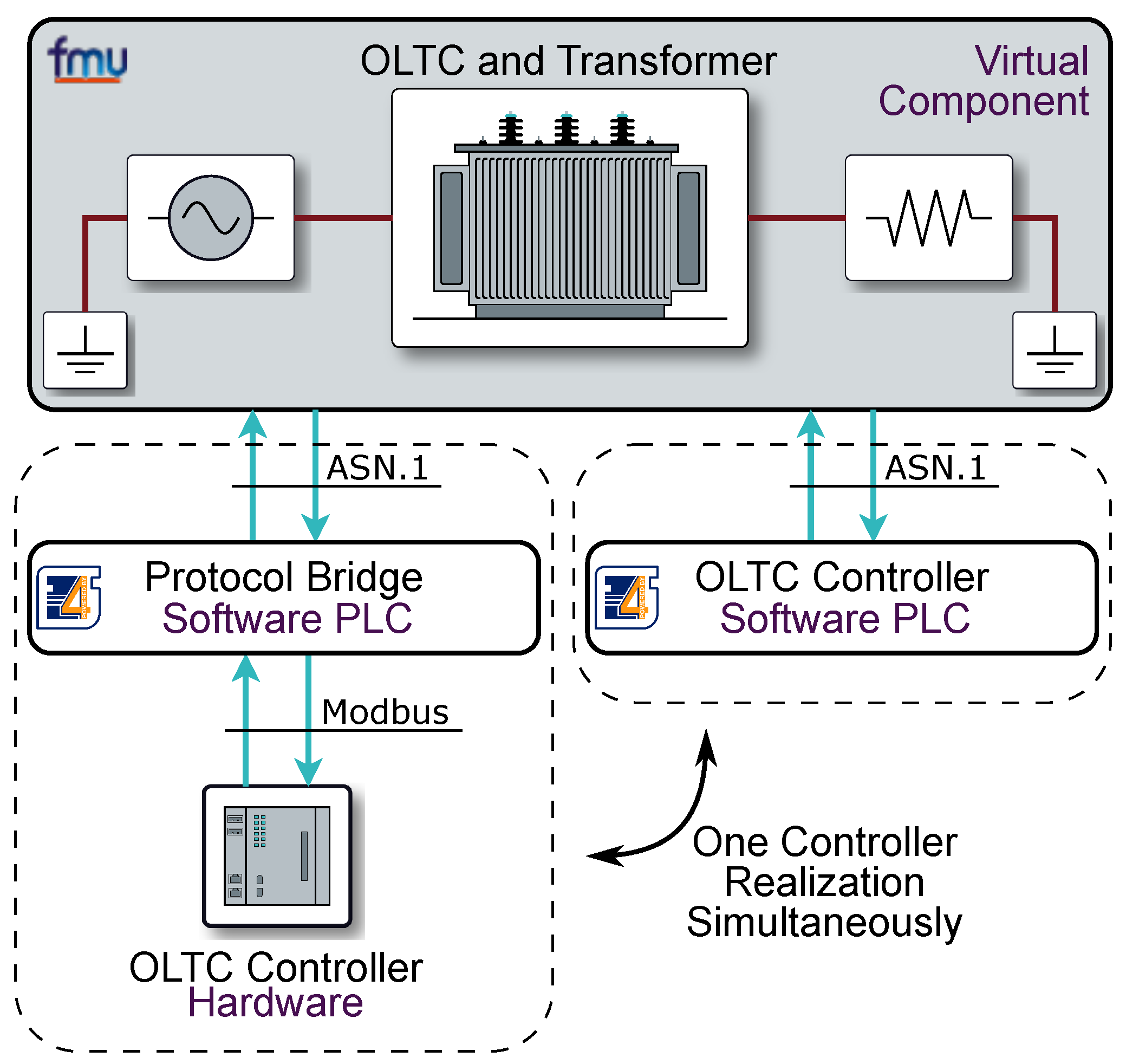
Based on the reference model, three experimental setups were designed, illustrated in Figure 4. In each experiment, a virtual component, which comprised the OLTC, the transformer, the load, and the voltage source, was instantiated. The FMU defining the virtual component was directly exported from the reference model using the FMI 2.0 for Model Exchange standard via the FMI Kit for Simulink in Version 2.4.0. Two controller implementations with identical functionality were manually derived from the reference model and alternatively used in the experiments.

4.1.2. Controller Hardware

The first OLTC controller was an embedded hardware implementation, which was interfaced via a Modbus TCP/IP connection. The communication interface enabled querying control outputs directed to the OLTC and allowed setting the low voltage readings and whether the OLTC was ready to initiate a switching operation. In order to avoid overloading the embedded controller and the resulting frequent packet loss, a minimum polling interval of 200 ms was chosen. Since the OLTC controller hardware and the reference model encoded control actions differently, a simple protocol bridge was deployed. The bridge, which was implemented in a software PLC, periodically polled the hardware controller and sent change events to the virtual component. Upon receiving events from the virtual component, data could be directly relayed without awaiting the next polling cycle.

4.1.3. Software PLC Controller

Polling external hardware introduced significant delay. To study the effects of the event mapping algorithms in more detail, a second event-based controller that was solely implemented in a software PLC was derived from the reference model. In contrast to the hardware controller, output events could be directly sent, and protocol translation was avoided. Since both controller implementations received measurements and status signals from the virtual component and sent control outputs back, a closed-loop simulation was performed. The virtual OLTC started its operation as soon as a control signal was received, and the controller continued its operation as soon as the OLTC finished its last switching command. Due to the partially asynchronous behavior, synchronization and communication delays were directly reflected in the experiment outcome.

4.1.4. Configuration

To cope with the high computational complexity of the transformer model, integration of the FMU state was achieved with the help of the Adams–Bashforth–Moulton variable step-size solver, as implemented in the Sundials sub-library [29]. All experiments used an initial step-size of 10 ms and iteratively located state events until a precision of 1 ms was reached, using relative and absolute integrator tolerances of 10 4 . Synchronization and prediction step sizes were chosen such that little delay was accumulated and real-time deviations quickly decayed to zero. In particular, a synchronization step size of 100 ms for periodic synchronization and a prediction horizon of 1 s supported by locally stored intermittent results every 100 ms for predictive event mapping were selected.
The simulation outcome in terms of model in- and out-put variables was recorded whenever an event was exchanged. Each event record contained the nominal event time and every associated variable value. Alternative instrumentation points may include the external hardware or the software PLC, but to gain a consistent view according to the reference clock of the experiment, only the FMITerminalBlock records were taken into account. Since each experiment covered multiple switching operations and numerous event emissions, synchronization was inherently repeated within one experiment run.
Both the software PLC and the virtual component were executed with a high process priority on a Windows 7 PC featuring 6 GB of RAM and an Intel Xeon dual core CPU W3505, clocked at 2.53 GHz. All software PLC configurations were designed and executed by Eclipse 4diac [30]. The hardware OLTC controller was based on a development board featuring an ATmega2560 microcontroller from Microchip, running at 16 MHz, and a WIZnet W5100 Ethernet-TCP/IP driver, which implemented both the control logic and the Modbus TCP/IP interface.

4.2. Timing Evaluation Method

In order to assess the timing quality, the following generalized method was developed and applied to each experiment.

4.2.1. Timing Record Fusion

Since the network, which was used to connect the virtual component, was considered as part of the automation system, the real-time instant of an FMI event was approximated by two locally recorded time stamps. The first one dated the beginning of the event distribution and was taken as soon as the event was scheduled. The second time stamp was recorded as soon as all event outputs were calculated and the event was successfully distributed. Additionally, the real-time instant at which an event was added to the queue (i.e., when it was received or predicted) and the time an event became outdated were tracked to gain further insights.
For each real-time record, a single independent entry was logged by FMITerminalBlock. In the post-processing steps, the independent records were linked such that each time stamp was associated with the corresponding event entity. To simplify the prototypical program flow and to increase the level of parallelism, FMITerminalBlock did not assign unique event identifiers, and the nominal event time was used to match timing records. An algorithm that emulated the state of the event queue in post-processing was used to associate the timing records with the corresponding event entity. An error was issued in case of ambiguities, but none were observed during the experiments.

4.2.2. Timing Metrics

From the recovered dataset, two classes of timing metrics were used. The first one was the delay metrics comparing the actual time stamp to the nominal event time at a particular processing stage. Most importantly, the delay at the beginning and the end of the distribution stage and the maximum observed delay were considered. The second class of metrics operated on the linked event data and tracked the duration of an operation such as event prediction and distribution. In particular, distribution time was taken to estimate the event jitter and prediction time to assess the computational effort of solving the model.

4.3. Results and Discussion

4.3.1. Timing

Table 1 summarizes the main delay metrics. One may note the maximum distribution delay of both predictive approaches of 187 ms. This was nearly the amount of two periodic synchronization steps and therefore larger than the maximum delay in the periodic configuration of 47 ms emission plus 100 ms synchronization delay. Nevertheless, only the average distribution delay of the predictive software PLC with approximately 90 ms was considerably larger than the 22 ms to 28 ms in the other experiments, although for all predictive experiments, the same FMITerminalBlock configuration was used. Both predictive experiments showed a maximum duration of 172 ms for a full prediction and average values of 111 ms and 116 ms with standard deviations of 42 ms and 48 ms, respectively, indicating similar efforts of predicting one event.
It turned out that the safeguard condition (4), which stated that two events must not be triggered close to each other, was regularly violated and that 71% of all events in the predictive PLC controller experiment were triggered before the maximum prediction time expired. Thirty three percent of the events in the experiment were even triggered immediately after another event. Due to increased latencies, the share of events triggered as close as 172 ms dropped to 53% in the hardware controller experiment, and consequently, a reduced average delay was observed.
The models showed mechanical switching times as short as 500 ms and electric transients well below 100 ms. Consequently, the simulation results needed further considerations regarding their accuracy to better allow studying the effects of the real-time execution on the simulation outcome.

4.3.2. Simulation Outcome

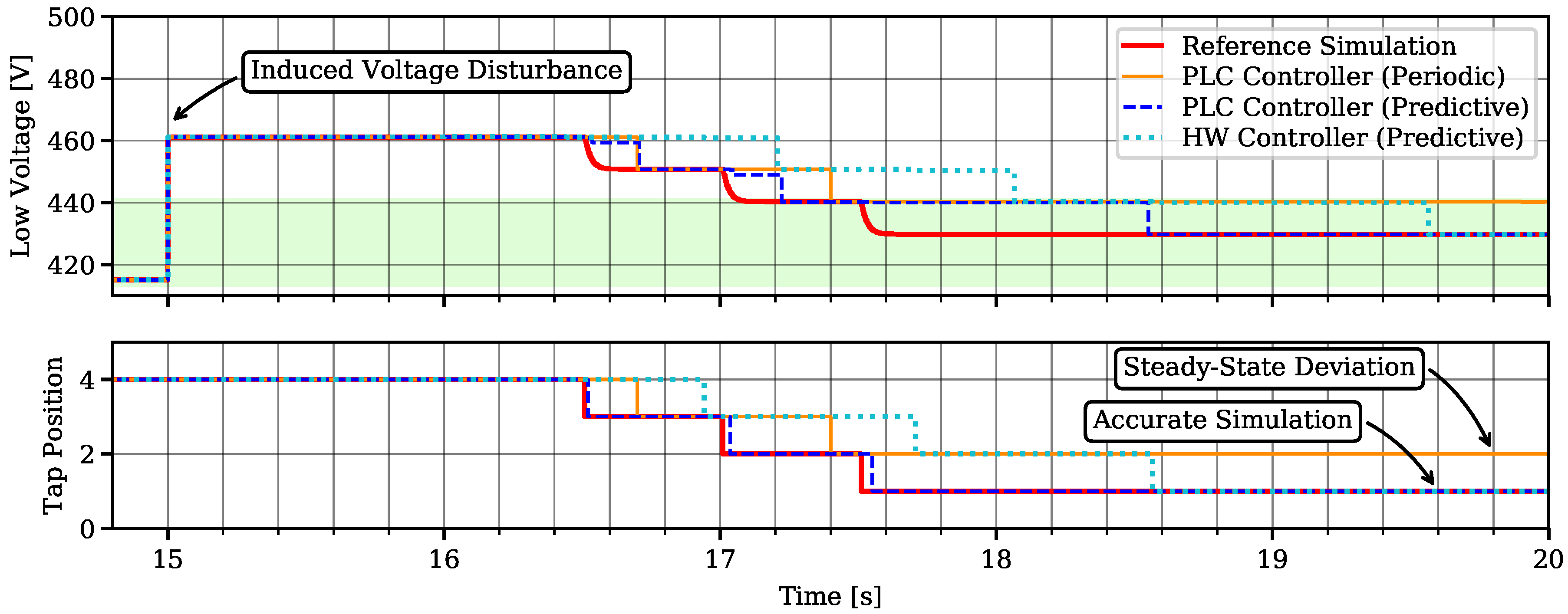
Figure 5 shows exemplary control actions that brought the simulated low voltage back to the targeted middle band for all three conducted experiments. One can note that for the predictive software PLC configuration, only a little deviation could be seen in the tap switching timing. Nevertheless, timing analysis of the displayed interval showed a maximum distribution delay of 172 ms, but most delays became masked because the transformer was still busy when highly delayed events arrived and the results were not disturbed. In contrast, a maximum distribution delay of only 38 ms was recorded in the hardware controller experiment of Figure 5, but the increased communication delay in the automation system strongly contributed to the observed result.
Since low voltage readings of the virtual component were transferred and updated upon event occurrence only, intermediate simulation results were solely plotted in the reference simulation. Nevertheless, all control actions were initiated by an event, and hence, predictive event mapping could more accurately sample and communicate the model outputs before it transited to the new steady-state value. Contrarily, periodic event mapping deferred communication to the next synchronization point where the new steady-state value was already established. One can note that, due to late sampling, the last switching operation was omitted, and a steady-state deviation for the periodically synchronized virtual component appeared.

5. Conclusions

The paper introduced and successfully demonstrated the concept of generic virtual components, which bridge the gap between FMI-based models and event-based automation systems. The analysis of periodic and extrapolation-based predictive event mapping showed that:
  • only soft real-time operation was feasible, in general,
  • predictive operation introduced strict bounds of a delay-free synchronization that were rarely met in practice, and
  • periodic event mapping always had to delay and accumulate events.
Experiments designed to study the boundaries of the mapping approaches via a prototypical interface application demonstrated the benefits of event-accurate predictive mapping. Although the hybrid model regularly violated the strict real-time condition, a satisfying best-effort synchronization could be achieved, and deviations when using periodic event mapping could be eliminated. In particular, FMI-based models without good real-time simulator support, such as various thermal models and models that require event-accurate coupling, may specifically profit from the presented work.

Author Contributions

Conceptualization, M.H.S., E.W., and B.H.; methodology, M.H.S.; software, M.H.S. and E.W.; validation, M.H.S.; formal analysis, M.H.S. and B.H.; investigation, M.H.S. and N.A.; writing, original draft preparation, M.H.S. and B.H.; writing, review and editing, B.H. and E.W.; visualization, M.H.S.; supervision, W.K., B.H., and E.W.; project administration, E.W. All authors read and agreed to the published version of the manuscript.

Funding

This work is partly supported by the European Union’s Horizon 2020 research and innovation program (H2020/2014-2020) under project “ERIGrid” (Grant Agreement No. 654113).

Conflicts of Interest

The authors declare no conflict of interest.

Abbreviations

The following abbreviations are used in this manuscript:
BFBBasic Function Block
CFBComposite Function Block
FBFunction Block
FMUFunctional Mock-up Unit
FMIFunctional Mock-up Interface
HILHardware-in-the-Loop
ODEOrdinary Differential Equation
OLTCOn-Load Tap Changer
PLCProgrammable Logic Controller
RTIRun-time Infrastructure
SCADASupervisory Control and Data Acquisition
SIFBService Interface Function Block
SSDService Sequence Diagram
WCETWorst Case Execution Time

References

  1. Nieße, A.; Tröschel, M.; Sonnenschein, M. Designing dependable and sustainable Smart Grids–How to apply Algorithm Engineering to distributed control in power systems. Environ. Model. Softw. 2014, 56, 37–51. [Google Scholar] [CrossRef]
  2. Yang, C.H.; Zhabelova, G.; Yang, C.W.; Vyatkin, V. Cosimulation Environment for Event-Driven Distributed Controls of Smart Grid. IEEE Trans. Ind. Inform. 2013, 9, 1423–1435. [Google Scholar] [CrossRef]
  3. Lin, H.; Sambamoorthy, S.; Shukla, S.; Thorp, J.; Mili, L. Power system and communication network co-simulation for smart grid applications. In Proceedings of the 2011 IEEE PES Innovative Smart Grid Technologies (ISGT 2011), Anaheim, CA, USA, 17–19 January 2011; pp. 1–6. [Google Scholar] [CrossRef]
  4. Viehweider, A.; Lauss, G.; Lehfuss, F. Stabilization of Power Hardware-in-the-Loop simulations of electric energy systems. Simul. Model. Pract. Theory 2011, 19, 1699–1708. [Google Scholar] [CrossRef]
  5. Heinzl, B.; Raich, P.; Preyser, F.; Kastner, W. Simulation-based Assessment of Energy Efficiency in Industry: Comparison of Hybrid Simulation Approaches. IFAC-PapersOnLine 2018, 51, 689–694. [Google Scholar] [CrossRef]
  6. Blochwitz, T.; Otter, M.; Arnold, M.; Bausch, C.; Clauß, C.; Elmqvist, H.; Junghanns, A.; Mauss, J.; Monteiro, M.; Neidhold, T.; et al. The functional mockup interface for tool independent exchange of simulation models. In Proceedings of the 8th International Modelica Conference, Dresden, Germany, 20–22 March 2011; pp. 20–22. [Google Scholar]
  7. Widl, E.; Müller, W.; Elsheikh, A.; Hörtenhuber, M.; Palensky, P. The FMI++ library: A high-level utility package for FMI for model exchange. In Proceedings of the 2013 Workshop on Modeling and Simulation of Cyber-Physical Energy Systems (MSCPES), Berkeley, CA, USA, 20–22 May 2013; pp. 1–6. [Google Scholar] [CrossRef]
  8. Müller, W.; Widl, E. Linking FMI-based components with discrete event systems. In Proceedings of the 2013 IEEE International Systems Conference (SysCon), Orlando, FL, USA, 15–18 April 2013; pp. 676–680. [Google Scholar] [CrossRef]
  9. Strasser, T.; Stifter, M.; Andrén, F.; Palensky, P. Co-Simulation Training Platform for Smart Grids. IEEE Trans. Power Syst. 2014, 29, 1989–1997. [Google Scholar] [CrossRef]
  10. Müller, S.C.; Georg, H.; Küch, M.; Wietfeld, C. INSPIRE—Co-Simulation of Power and ICT Systems for Evaluation of Smart Grid Applications. At-Automatisierungstechnik 2014, 62, 315–324. [Google Scholar] [CrossRef]
  11. Awais, M.U.; Palensky, P.; Mueller, W.; Widl, E.; Elsheikh, A. Distributed hybrid simulation using the HLA and the Functional Mock-up Interface. In Proceedings of the IECON 2013—39th Annual Conference of the IEEE Industrial Electronics Society, Vienna, Austria, 10–13 November 2013; pp. 7564–7569. [Google Scholar] [CrossRef]
  12. Modelica Association Project Functional Mock-up Interface. In Functional Mock-Up Interface for Model Exchange; 2010; Available online: https://svn.modelica.org/fmi/branches/public/specifications/v1.0/FMI_for_ModelExchange_v1.0.pdf (accessed on 26 February 2020).
  13. Modelica Association Project Functional Mock-up Interface. In Functional Mock-Up Interface for Model Exchange and Co-Simulation; 2014; Available online: https://svn.modelica.org/fmi/branches/public/specifications/v2.0/FMI_for_ModelExchange_and_CoSimulation_v2.0.pdf (accessed on 26 February 2020).
  14. Eker, J.; Janneck, J.W.; Lee, E.A.; Liu, J.; Liu, X.; Ludvig, J.; Neuendorffer, S.; Sachs, S.; Xiong, Y. Taming heterogeneity—The Ptolemy approach. Proc. IEEE 2003, 91, 127–144. [Google Scholar] [CrossRef] [Green Version]
  15. IEC 61499-1/Ed.2: Function Blocks—Part 1: Architecture; IEC: Geneva, Switzerland, 2012.
  16. Vyatkin, V. The IEC 61499 standard and its semantics. IEEE Ind. Electron. Mag. 2009, 3, 40–48. [Google Scholar] [CrossRef]
  17. Strasser, T.; Zoitl, A.; Christensen, J.H.; Sünder, C. Design and Execution Issues in IEC 61499 Distributed Automation and Control Systems. IEEE Trans. Syst. Man Cybern. Part C: Appl. Rev. 2011, 41, 41–51. [Google Scholar] [CrossRef]
  18. Vyatkin, V. IEC 61499 as Enabler of Distributed and Intelligent Automation: State-of-the-Art Review. IEEE Trans. Ind. Inform. 2011, 7, 768–781. [Google Scholar] [CrossRef]
  19. Strasser, T.; Auinger, F.; Zoitl, A. Development, implementation and use of an IEC 61499 function block library for embedded closed loop control. In Proceedings of the INDIN ‘04 2004 2nd IEEE International Conference on Industrial Informatics, Berlin, Germany, 24–26 June 2004; pp. 594–599. [Google Scholar] [CrossRef]
  20. Lindgren, P.; Lindner, M.; Lindner, A.; Vyatkin, V.; Pereira, D.J.; Pinho, L.M. A Real-Time Semantics for the IEC 61499 standard. In Proceedings of the 2015 IEEE 20th International Conference on Emerging Technologies & Factory Automation (ETFA 2015), Luxembourg, 8–11 September 2015. [Google Scholar]
  21. Yang, C.H.; Vyatkin, V.; Cheng Pang, V. Model-Driven Development of Control Software for Distributed Automation: A Survey and an Approach. IEEE Trans. Syst. Man Cybern. Syst. 2014, 44, 292–305. [Google Scholar] [CrossRef]
  22. Zehetner, J.; Stettinger, G.; Kokal, H.; Toye, B. Echtzeit-Co-Simulation für die Regelung eines Motorprüfstands. ATZ Automob. Z. 2014, 116, 40–45. [Google Scholar] [CrossRef]
  23. Gunnarsson, S. Evaluation of FMI-Based Workflow for Simulation and Testing of Industrial Automation Applications. Master’s Thesis, Department of Automatic Control, Lund University, Lund, Sweden, 2016. [Google Scholar]
  24. Erwall, C.; Mårtensson, O. Model-Based Design of Industrial Automation Solutions Using FMI. Master’s Thesis, Department of Automatic Control, Lund University, Lund, Sweden, 2016. [Google Scholar]
  25. Spiegel, M.H.; Leimgruber, F.; Widl, E.; Gridling, G. On using FMI-based models in IEC 61499 control applications. In Proceedings of the 2015 Workshop on Modeling and Simulation of Cyber-Physical Energy Systems (MSCPES), Seattle, WA, USA, 13 April 2015; pp. 1–6. [Google Scholar] [CrossRef]
  26. Hegny, I.; Wenger, M.; Zoitl, A. IEC 61499 based simulation framework for model-driven production systems development. In Proceedings of the 2010 IEEE Conference on Emerging Technologies and Factory Automation (ETFA), Bilbao, Spain, 13–16 September 2010; pp. 1–8. [Google Scholar] [CrossRef]
  27. Kopetz, H. Real-Time Systems; Design Principles for Distributed Embedded Applications; Real-Time Systems Series; Springer Science+Business Media: LLC: Boston, MA, USA, 2011. [Google Scholar] [CrossRef]
  28. Spiegel, M.H. Linking Simulation and Automation Infrastructure—A Study Based on the FMI and IEC 61499. Master’s Thesis, Technische Universität Wien, Wien, Austria, 2018. [Google Scholar]
  29. Hindmarsh, A.C.; Brown, P.N.; Grant, K.E.; Lee, S.L.; Serban, R.; Shumaker, D.E.; Woodward, C.S. SUNDIALS: Suite of nonlinear and differential/algebraic equation solvers. ACM Trans. Math. Softw. (TOMS) 2005, 31, 363–396. [Google Scholar] [CrossRef]
  30. Strasser, T.; Rooker, M.; Ebenhofer, G.; Zoitl, A.; Sunder, C.; Valentini, A.; Martel, A. Framework for distributed industrial automation and control (4DIAC). In Proceedings of the INDIN 2008 6th IEEE International Conference on Industrial Informatics, Daejon, Korea, 13–16 July 2008; pp. 283–288. [Google Scholar]
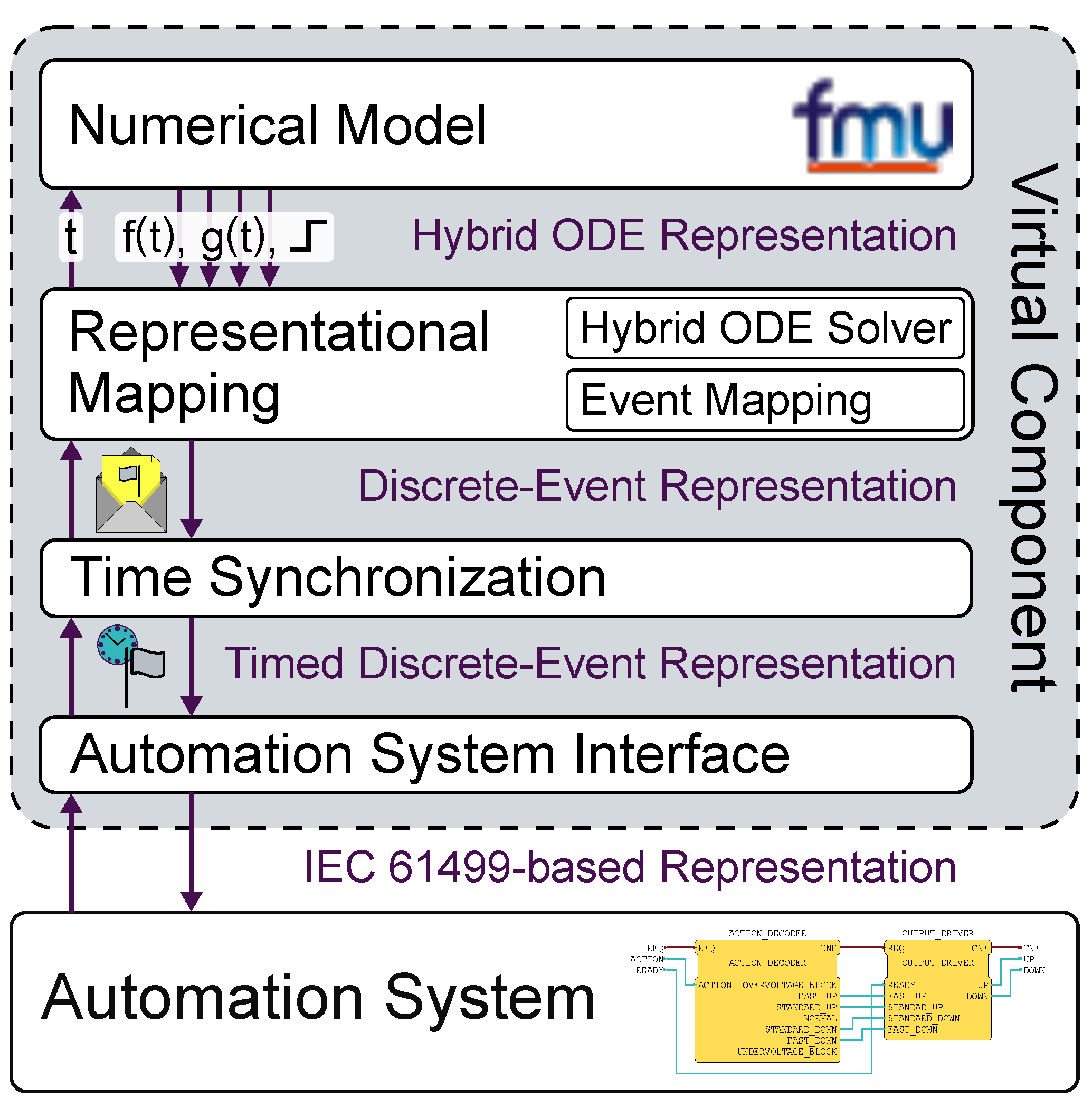
Figure 1. Abstract system model.
Applsci 10 01611 g001
Figure 2. Periodic event mapping.
Applsci 10 01611 g002
Figure 3. Predictive event mapping: Predicted events will be invalidated and updated as soon as events from the automation system arrive.
Applsci 10 01611 g003
Figure 4. Experimental setups.
Applsci 10 01611 g004
Figure 5. Exemplary switching operation.
Applsci 10 01611 g005
Table 1. Delay metrics.
ExperimentDist. StageDelay Metrics
SamplesMean (s)Variance ( s 2 )Max. (s)
PLC PredictiveBegin2820.09030.0033310.187
End2820.09090.0033350.187
PLC PeriodicBegin7710.02622.176 × 10 5 0.0336
End7710.02754.919 × 10 5 0.0468
HW PredictiveBegin2220.02190.0013540.187
End2220.02240.0013810.187