1. Introduction
UAVs and USVs play an important role in marine environment monitoring, marine mapping, and maritime patrol and rescue [
1,
2,
3]. In scenarios such as ocean environment monitoring, it is difficult to perform large-scale coverage monitoring in a short time, owing to the limitation of the ship’s movement speed and maneuverability. Fixed-wing UAVs have the advantage of being fast, maneuverable, long range, and long endurance. They can quickly perform a large-scale coverage of their surrounding environment, especially when multiple UAVs work together at the same time. In addition, the small fixed-wing UAV technology has become relatively mature, the development cost is low, and box storage is available; thus, it has the advantages of occupying a small space and has been widely used. If the USV can be combined with small fixed-wing UAVs, the USV will serve as the mother ship of the UAVs. It will provide energy supply, unified planning, and storage. In addition, the UAV will serve as a large-scale fast and efficient search operation tool, which will greatly expand the application of UAV–USV marsupial platform in marine environment.
The marsupial unmanned platform is a multi-robot system composed of a mother robot and one or more child robots that has been studied and applied in some scenarios. Anderson developed a ground–ground marsupial platform MACS for ground information collection [
4]. Corke developed a ground–air marsupial unmanned platform for the automatic laying of small sensing devices [
5]. Fletcher developed an air–ground marsupial unmanned platform [
6]. At present, air-to-water surface marsupial unmanned platforms are mainly composed of rotary UAVs and USVs [
1,
2,
3,
7,
8]. For a marsupial platform consisting of fixed-wing UAVs and USVs, due to the difficulty of recovering fixed-wing UAVs on USVs, it is necessary to design an efficient and reliable autonomous recovery system for small fixed-wing UAVs. This is the key to the application of fixed-wing UAVs in marine environment.
There are many types of ship-based fixed-wing UAV landing or recovery methods, as shown in
Figure 1. Several typical landing or recovery methods include runway arrested landing (
Figure 1a) [
9], net recovery (
Figure 1b) [
10], parachute/parafoil recovery (
Figure 1c) [
11], cable-hook recovery (
Figure 1d) [
12], skyhook recovery, post-stall landing, bio-inspired perched landing, wind-sock recovery, and trapeze recovery [
13]. Among these, runway arrested landing is mainly used for large ships, because large ships have large decks, their mass and size are large, and they are not sensitive to the movement of waves. The net recovery system requires high-end guidance accuracy and energy absorption buffer level. If a recovery error occurs, the UAV may hit the ship’s equipment. Generally, this kind of dangerous recovery method is not used in such scenarios. In the method of parachute/parafoil recovery, the parachute needs to occupy the space of the fuselage with limited space. The UAV descends quickly, and the body is easily damaged by the stronger water impact. UAVs must have sufficient water resistance and need to be salvaged with professional marine salvage equipment. Skyhook recovery requires the use of a certain length of vertical suspension wire, which is difficult to achieve on small unmanned ships. Cable hook recovery is an effective means to realize automatic recovery under conditions such as large waves, wind, and turbulence in the open sea. It mainly works well with small fixed-wing UAVs [
13]. However, a cable-hook recovery system with weak attitude adjustment capability will produce a situation similar to the net recovery. That is, if a recovery error occurs, the UAV may hit the ship’s equipment. If the attitude active adjustment capability of the cable-hook recovery system can be greatly improved and coordinated in real time according to the flight conditions of the UAV, an efficient and safe autonomous recovery system can be possible.
In recent years, some novel UAV recovery methods have been developed. Zhang developed a hierarchical control structure for autonomous landing of fixed-wing UAVs [
14]. Joo investigated a UAV navigation system with aid from an external camera for landing [
15]. Kim developed an autonomous vision-based net recovery system for small fixed-wing UAVs [
16]. Kong focused on the problem of landing an UAV in unknown and Global Navigation Satellite System (GNSS)-denied environments, based on an infrared stereo vision system [
17]. Fan proposed a method to make UAV only use the airborne front-looking camera to find and align the runway [
18]. Klausen used two multirotor-drone suspension nets to recover small fixed-wing UAVs [
19,
20]. It coordinated the net-based recovery system and the fixed-wing UAV by constructing a virtual runway, and finally caused the fixed-wing UAV to crash into the net and land the net-based recovery system on the USV.
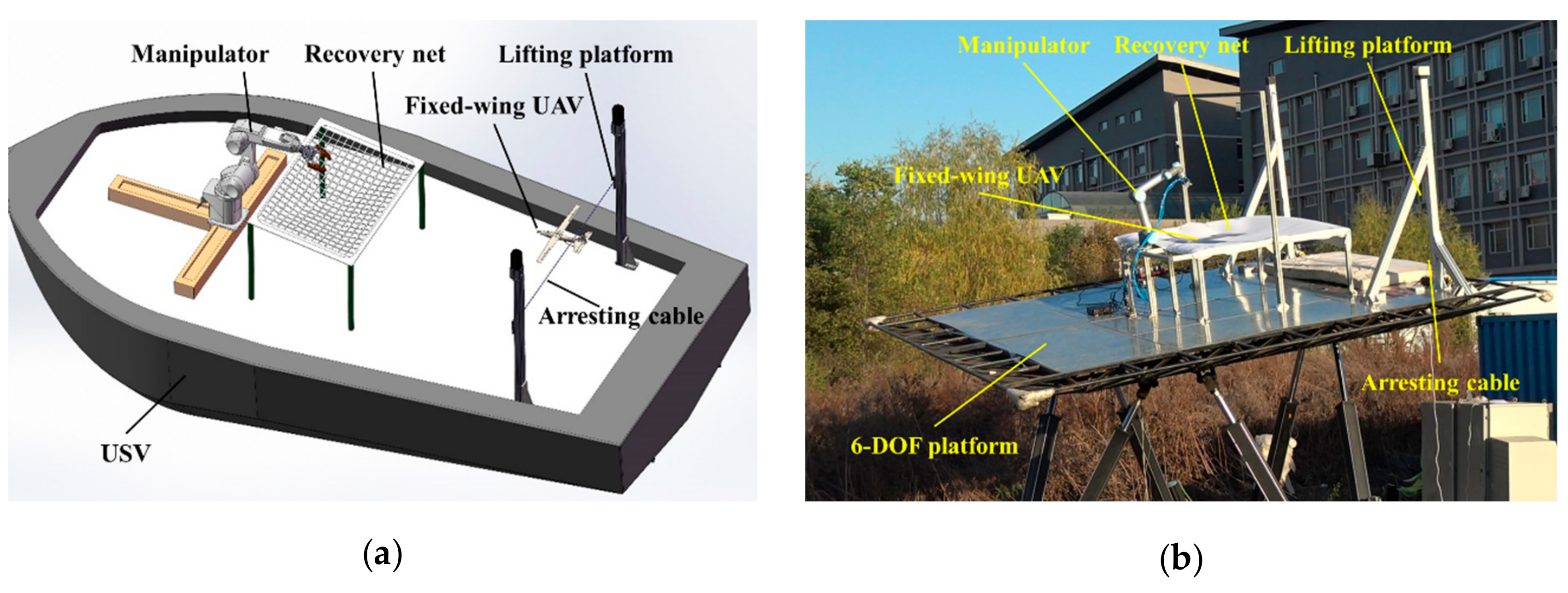
However, these abovementioned methods and systems do not take into account the capture of the fixed-wing UAV from the net and the re-release of the UAV after landing on the USV, the fully autonomous recovery, and release of fixed-wing UAVs on USVs has not been achieved. In order to solve this problem, based on the analysis of existing methods, we have developed an adaptively adjustable cable hook recovery system, an autonomous flexible grasp-and-place UAV system, and realized full autonomous recovery of small fixed-wing UAVs on USV [
21]. This system mainly includes an active adjusting cable hook system, a recovery net, and a compliant grasping and placing system. Its design diagram and physical simulation system are shown in
Figure 2. The basic considerations of the proposed system design are motion compensation, wherein it compensates for USV lateral and longitudinal sway motions; UAV control deviations; and flexible mechanisms and ropes, where movement energy is quickly absorbed to reduce damage to the UAV.
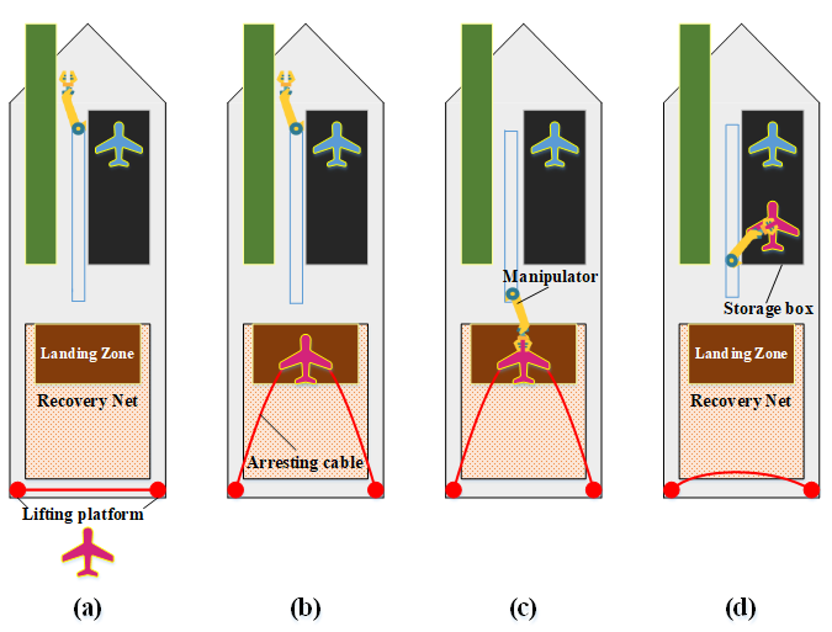
During the recovery process, the cable-hook system can actively adjust and maintain the attitude of the arresting cable according to the UAV’s flight status, along with the attitude change of the USV and the undulating sea. At the same time, through coordinated adjustment with the UAV, its tail hook can be successfully hooked to the arresting cable, so that the speed of the UAV decreases rapidly and it is landed on the recovery net. The compliant grasping and placing system visually recognizes the position and attitude of the UAV and removes the UAV from the arresting rope and recovery net, using pneumatic suction cups, and places it in a storage box. The main recovery process is shown in
Figure 3.
The most significant contribution of this study is that, for the first time, a fully autonomous solution covering the entire process of using a small-scale fixed-wing UAVs from landing to recovery and placement is proposed. The key technology of this system is introduced, and the physical entity production and experimental verification of the system are carried out on this basis. This system can provide a very valuable reference for the fully autonomous recovery of small fixed-wing UAVs on USVs. A wide and thorough literature survey has revealed that, the study described here, has not been published yet.
The rest of this paper is organized as follows. In
Section 2, the main features and advantages of the fully autonomous recovery system and the key technical issues of the system are introduced. In
Section 3, we introduce the specific contents of the key technologies of the recovery system, including active modeling of the UAV–USV heterogeneous platform motion model, accurate estimation of the highly dynamic relative motion of the heterogeneous platform, and dynamic analysis of the arresting cable system. The experimental system, key experimental techniques, and verification process are described in detail in
Section 4. The experimental results and analysis are given in
Section 5, followed by summary and further discussion in
Section 6.
2. Fully Autonomous Recovery System
This section begins with an analysis of the challenges involved in the development and application of fully autonomous recovery systems built on USVs. This is followed by an explanation of the characteristics and advantages of the system designed in this work, in order to solve the aforementioned challenges. Based on this, the key technical issues of the system are briefly explained.
First, in order to ensure a smooth implementation of the verification test and the stability of the system, it is necessary to study methods such as USV motion simulation and compensation stabilization in the case of wave fluctuations. Since the two types of platforms, UAVs and USVs, are heterogeneous platforms, they have many differences in structure, kinematics and dynamic models, and control methods [
22,
23,
24,
25,
26]. Therefore, techniques such as active modeling of relative motion of heterogeneous platforms, coordinated autonomous control of heterogeneous platforms, and relative position and attitude measurement during high-speed motion of heterogeneous platforms need to be studied. At last, in order to make the recovery system have a certain compliance, and to ensure a certain compliance and buffer time when the UAV is in contact with the recovery system or the environment or there is a collision or impact [
27,
28], the compliance control of recovery systems needs to be studied.
2.1. Development Challenges and System Advantages
2.1.1. Difficulties and Challenges of System Development
The system is required to overcome the complex conditions of the surface of the sea, to achieve high-precision moving-target positioning and attitude determination (perception challenge). Sea wind and waves have an impact on the attitude of the USV at all times, and it is difficult to maintain it consistently. This brings about an uncertainty in the landing process of the UAV and makes it difficult for the recovery system to retrieve the UAV without damage.
The system needs to have active/passive control capabilities for energy compliance conversion during recovery process, such as converting the kinetic energy when a UAV hits an arresting cable into the potential energy of the arresting cable (control challenges). It also needs to overcome the uncertainty of the position of the UAV and have a compliance-grasping ability during the grasping and placement process.
A collaboration of different technologies is necessary to coordinate amidst dynamic differences and environmental uncertainties (coordination challenges). In this case, a heterogeneous coordination between the arresting cable system and the fixed-wing UAV proved difficult.
2.1.2. Features and Advantages of Our System
The arresting cable system is intelligent and actively performs attitude compensation adjustment based on the attitude of the USV, which also maintains attitude stably. Further, the arresting cable system and the UAV can coordinate and adjust attitude heterogeneously. To ensure safety, a flexible mechanism and protection net is designed to prevent UAVs from colliding with the USV. The manipulator operates flexibly, assisting the UAV’s recovery, release, and storage. Pneumatic grasping devices and manipulator compliance control can make the automated UAV grasping and placing process accurate and smooth.
Besides, the USV is a host that carries multiple UAVs and provides a basis for cross-domain heterogeneous collaboration.
2.2. UAV Motion Simulation and Wave Compensation for Stabilization
The attitude of the UAV has a significant influence on the positioning and cooperative control of the UAV–USV platform, the active adjustment of the arresting cable, and the stable grasping of the manipulator. The uncertainty of the attitude of the USV due to wind and wave interferences will pose a serious challenge to the safe release and precise recovery of the UAV on the USV. Aiming at this problem, a wave motion model and a USV motion model are established to effectively predict the six-dimensional motion of the USV. Based on this predicted information, the attitude of the arresting cable is actively adjusted to maintain its position with the attitude of the UAV.
In order to overcome the impact of USV attitude changes on the system, a wave compensation system based on an adaptive Fast Fourier Transform (FFT) prediction algorithm and
filter is proposed [
29]. The algorithm is used to predict the heave motion model of the wave, to compensate the wave as synchronously as possible, and to eliminate high-frequency interference and make the compensation platform movement more stable. Utilizing the simulation software and the above algorithm, a USV platform and a three-degrees-of-freedom ocean wave simulation platform were constructed to perform six-degrees-of-freedom wave compensation. In the physical verification experiment, we use a six-axis simulation platform to simulate the six-dimensional movement of the USV and verify the relevant methods.
2.3. Active Modeling of UAV–USV Heterogeneous Platform Relative Motion
UAV–USV heterogeneous unmanned systems face many uncertain disturbances in practical applications, including dynamic differences caused by modal changes, external disturbances such as airflow, and random sway of the USV. The uncertainties caused by these disturbances are described as parameters and states in the dynamic model, and online estimation methods are used to obtain corresponding quantitative values, thereby achieving online model adjustment. The advantage is that the use of a simple structured model combined with uncertainty states and parameters to describe the dynamic model ensures that the structure of the model for the controller design is simplified and the accuracy of the model is not greatly reduced.
In addition, aerial fixed-wing UAV and surface USV platforms have completely different kinematics and dynamic characteristics. It is difficult to design corresponding cooperative control algorithms directly on the two independent dynamic models, and to ensure the accuracy of cooperative control. Therefore, we take the relative pose and speed between the two platforms as the basic state of the new system composed of the two platforms. We then construct a quantitative rule that the relative state changes with the input, and obtain the relative state according to the evolution of the control input of each platform. The construction of the relative dynamics model was realized. The methods in this section are explained in detail in
Section 3.1.
2.4. Cooperative Autonomous Control of Heterogeneous Platforms
Based on the model in
Section 2.3, the research of a heterogeneous platform collaborative autonomous control technology is carried out. First, the cooperative motion trajectory optimization scheme is described as a nonlinear dynamic optimization algorithm, which considers environmental obstacle constraints, cooperative tracking performance constraints, USV motion capability constraints, and uses distributed model predictive control (MPC) to achieve behavior coordination.
The algorithm is divided into two layers, as shown in
Figure 4, the coordination algorithm and the underlying motion control algorithm. The latter is the motion control algorithm of the single unmanned platform, which can fully consider the motion characteristics under the action of the underlying motion controller. The algorithm can be implemented in a distributed manner, to give real-time implementation of the algorithm under the consideration of multiple complex constraints.
The concepts of tracking control Lyapunov function and formation control Lyapunov function are introduced, where the former is the most direct embodiment of the motion control performance of each unmanned platform, and the latter is used as an extension of the former in the coordination optimization algorithm to ensure the coordination of each unmanned platform.
The research focuses on modeling the relative dynamics of the UAV–USV system, designing a reasonable tracking control Lyapunov function, and designing a reasonable coordinated control strategy based on the particularities of UAV and USV, so that the entire algorithm considers the dynamic constraints and multiple environmental constraints.
2.5. Relative Pose Measurement During High-Speed Movement of Heterogeneous Platforms
The relative position of the UAV and USV is an important indicator to achieve the coordination of heterogeneous platforms [
30,
31,
32,
33]. Based on the relative pose measurement during the high-speed movement of the UAV–USV heterogeneous platform, a real-time relative pose measurement system based on dynamic differential GPS is designed, and the system test and verification are completed. The system mainly includes UAV airborne modules, UAV shipborne modules, and ground control systems, as shown in
Figure 5. Based on this hardware system, the software design is carried out, and the spatial dynamic conversion of the guidance process is realized. The space point distance and the spatial positioning principle are used to implement the recovery guidance on the moving platform. The specific method is introduced in
Section 3.2.
The system can provide functions such as accurate relative position and speed, perfect fault alarm, and compatibility with multiple communication protocols. The ground control system can achieve remote monitoring and control, which facilitates system testing. The functions of the subsystem are as follows.
2.5.1. UAV Module
This mainly includes an on-board position calculation module, a positioning information acquisition board, and a corresponding wireless data transmission module. It can receive ground guidance information, and then send it to the flight control system after fusion processing for guiding landing and blocking recovery.
2.5.2. USV Module
This mainly includes a ship-based position calculation module, attitude and speed sensor, positioning information acquisition card, and wireless data transmission module, which realizes the guidance and position calculation and coordinate conversion, and the steering motor drive control capability. It is also necessary to provide sufficient control capabilities of actuators such as motor steering gears to ensure that the UAV can be safely recovered on USV.
2.5.3. Ground Control System
This system mainly realizes remote control and information collection and status monitoring of positioning system.
2.6. Compliance Control of Recycling System
2.6.1. Compliance Control of Manipulator
The manipulator recovery system needs to have a flexible operation capability, obstacle detection, and re-planning capabilities, to ensure compliance, safety, and intelligence in the recovery process. Through real-time feedback of external forces, if any, acceleration and end pose of the manipulator and the compliance control problem during the movement of the manipulator body is solved to ensure passive safety during physical contact. The basic idea is to realize real-time feedback of manipulator joint torque based on the manipulator joint torque sensor, and to realize torque control at the joint level. Based on this, the impedance controller is designed to achieve joint-level compliance control.
2.6.2. Collision Detection and Safety Strategy for Manipulator
The detection technology is based on a system dynamics model and uses a joint torque-based collision detection method. The main idea of this method is to find the transients due to possible collisions by comparing the torque measured by the joint sensor with the nominal torque calculated based on the dynamic model, that is, the expected torque when no collision occurs. In addition, by setting a threshold, it is used to determine whether a collision has occurred.
2.6.3. Reactive Behavior Planning
When the manipulator and the target are in the same physical space, it is important to ensure the safety of the grasp process. Therefore, while ensuring the rapid and timely response of the manipulator, it is also necessary to enable the manipulator to sense potential threats in the environment in real time, and to obtain environmental information in real time by using sensors to plan or correct the movement of the trajectory. This reactive behavior planning approach includes two parts, environmental awareness and motion planning. Environmental perception is mainly based on visual sensors, and motion planning mainly generates reasonable motion trajectories online for potential unsafe factors in uncertain environments [
34].
3. Main Method
In order to achieve full autonomous recovery of small fixed-wing UAVs on USV, key technologies such as active modeling of heterogeneous platform relative motion models, accurate estimation of high dynamic relative motion in complex environments, and dynamic feasibility verification of recovery devices are emphasized.
3.1. Active Modeling of UAV–USV Heterogeneous Platform Motion Model
3.1.1. Relative Dynamics Modeling of Heterogeneous Platforms
The establishment of a UAV–USV system mathematical model is the basis and key for subsequent collaborative planning and research. Since both UAV and USV are typical nonlinear systems, it is necessary to analyze the relative motion of the system based on establishing an accurate nonlinear model of a single unmanned system, to achieve dynamic modeling of the entire collaborative system.
First, the relative motion states between platforms are introduced to characterize the relative dynamics and kinematics of the UAV–USV system in free mode [
35,
36].
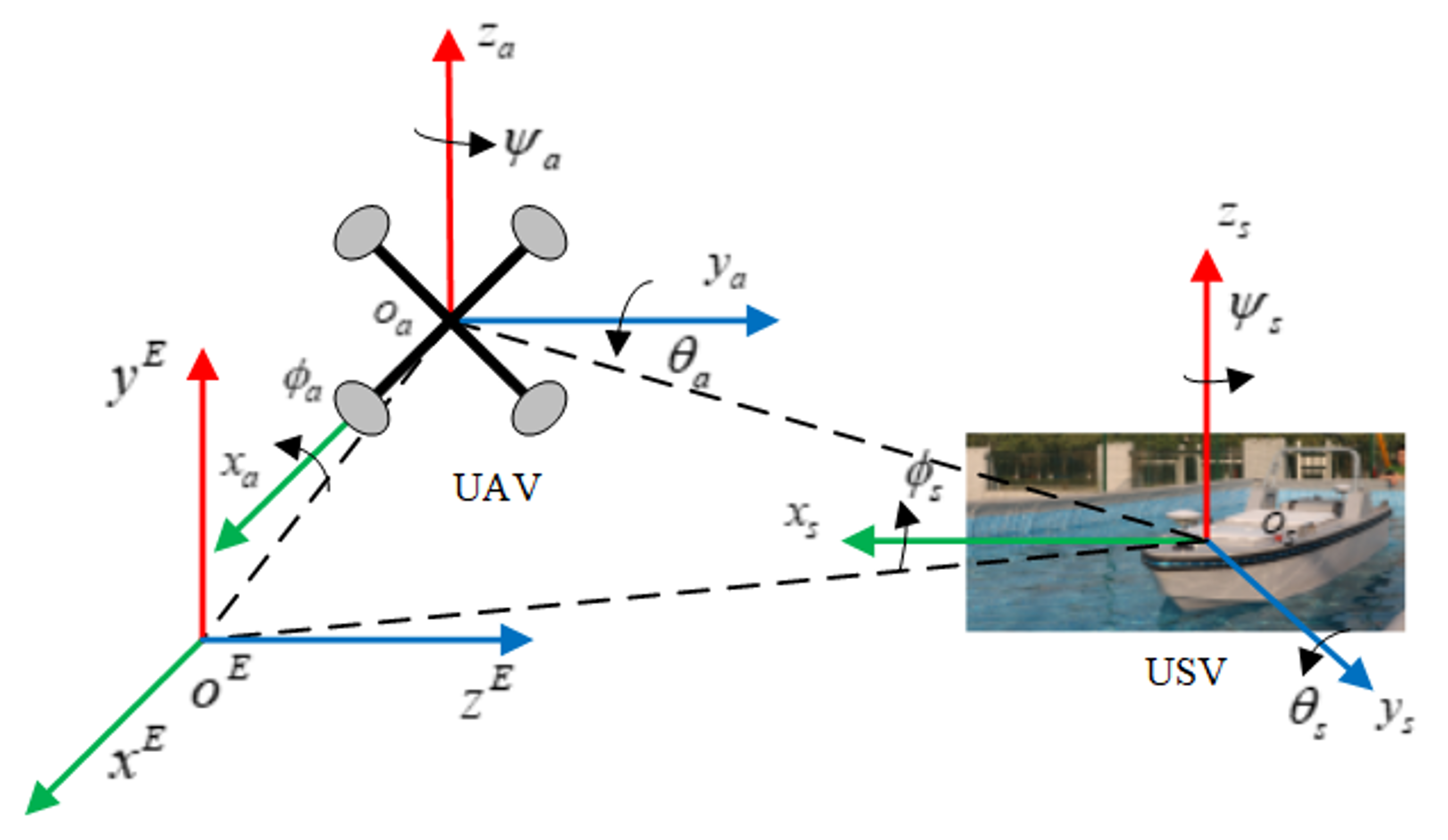
As shown in
Figure 6, consider the following relative motion states.
where
,
,
, and
indicate the global position, attitude, body shafting speed, and attitude angular velocity of the UAV (subscript a) and USV (subscript s), respectively. Moreover,
,
,
, and
are the relative attitude of the UAV–USV system.
is a transformation matrix, which represents the transformation of the USV body axis to the UAV body axis. The abovementioned relative pose analysis can effectively characterize the relative motion of the UAV–USV system in the free mode.
Considering that the relative pose model contains the UAV and USV dynamic characteristics and the form is relatively complicated, the above model is simplified as necessary. For the strong nonlinear characteristics of the model, the tensor product-based model transformation can be used to obtain the following linear variable parameter (LPV) model.
where
is the measurable variable parameter,
is the system state,
is the input, and the system matrix
and the input matrix
are generally linearly dependent on the variable parameter [
10].
3.1.2. Model Difference Online Estimation
In order to eliminate the influence of the model difference (wind, wave, and water flow) on the control system, it must be estimated online in real time and fed back to the controller for online correction. To this end, we introduce a joint estimation based on the simplified LPV model [
37,
38].
Joint estimation processes the state and the model difference simultaneously, that is, by constructing an augmented state that includes the state and the model difference, and building a model about the augmented state, and then using a single state estimation method to estimate the augmented state. Taking a USV as an example, its LPV dynamics is simplified and written as the equation of state as follows:
where
,
,
.
Assuming that the model difference,
, of the quasi-LPV simplified model is driven by noise
, then (3) can be rewritten as follows:
where
,
,
is process noise and satisfies
, and
is the measurement noise.
From the above estimation equation form, the joint estimation can obtain the optimal or suboptimal estimation of the joint distribution of the state and the model difference, instead of the respective optimal or suboptimal estimation of the state and the model difference. In addition, because the joint distribution requires only a single filter, there is no need to modify the original model, and the structure is simpler. It only needs to consider the estimation of the augmented state, so it is widely used when it is necessary to estimate the state and the model difference.
Suppose the sampling time, , is short, then , so that (4) can be discretized.
Considering that the LPV model (3) is a nonlinear model subject to the speed variable parameter () scheduling, UT (Unscented Transformation) is used to calculate the posterior mean and posterior variance of the system state in the nonlinear optimal Gaussian filter. This method can greatly improve the relative modeling accuracy of heterogeneous platforms and provide a basis for subsequent error-based feedforward controller design.
3.2. Accurate Measurement of High Dynamic Relative Motion of Heterogeneous Platforms
Aiming at the problem of high-precision positioning and guidance during the recovery process, overcoming the sensitivity of traditional measurement technologies in complex environments (light, electromagnetic, etc.), accurately measuring relative motion state (position, attitude, speed, etc.) can ensure real-time and accurate relative motion measurement. Based on the principle of satellite GPS relative lateral positioning, a mobile platform recovery guidance system was developed. This system provides the UAV with accurate guidance position relative to the USV and sends the attitude and speed data of the moving USV to the UAV.
3.2.1. Moving Platform Guidance and Coordinate System Conversion
The use of space point distance and space positioning principles to achieve moving platform guidance is far from being used for positioning and control of drones. Especially to realize the autonomous recovery of UAVs on high-speed moving USV, it is necessary to convert the local coordinate system on board the USV to the UAV navigation coordinate system-NED (North East Down) coordinate system. The corresponding moving platform guidance and coordinate transformation are shown in
Figure 7.
Based on the position information provided by the mobile platform guidance system, the UAV tracks from the current position,
, and lands on the center of mass,
, on the mobile platform. However, the moving platform guidance system is firmly connected to the mobile platform, and the position coordinate information provided is not the coordinates in the navigation coordinate system (NED coordinate system). We set
,
, and
in the
Figure 7 as the three vectors in the NED navigation coordinate system. In addition,
in the moving platform guidance coordinate system-ENU (East North Up) is denoted as
.
in the moving platform body coordinate system is denoted as
. Next, the transformation process from the moving platform guidance coordinate system to the NED navigation coordinate system is described in detail.
, where
is the origin of the coordinate system of the moving platform guidance system, which can be obtained through actual measurement. First convert the vector
to the NED coordinate system. For any vector (
), expressed as
in the body coordinate system and
in the NED coordinate system, the conversion of the vector
to
can be realized by the DCM (Direction Cosine Matrix):
where
R is the DCM, also known as the attitude matrix or roll matrix, which can be written in the form of Euler angles.
According to the above formula, the conversion formula of the vector
to the NED coordinate system is as follows:
, where
is the ENU coordinate system data output by the moving platform guidance system, and the conversion formula for converting it to the NED coordinate system is as follows:
where the expression of
is as follows:
Finally, the vector expression we can provide to the UAV in the NED navigation coordinate system is as follows:
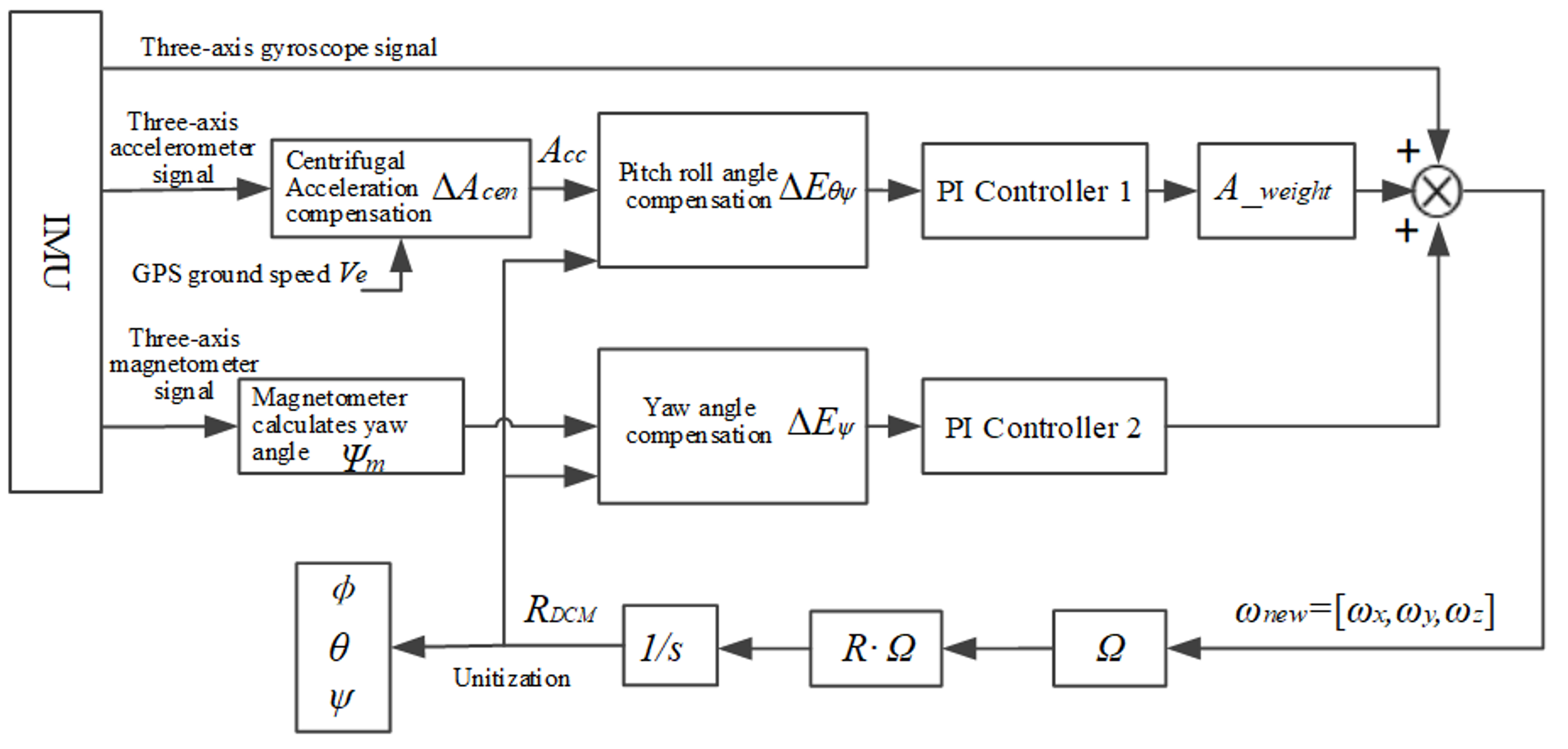
3.2.2. Accurate Attitude, Position, and Speed Measurement
The block diagram of the DCM attitude solution inertial sensor signal correction process is shown in
Figure 8.
The flowchart of DCM attitude solution is shown in
Figure 9.
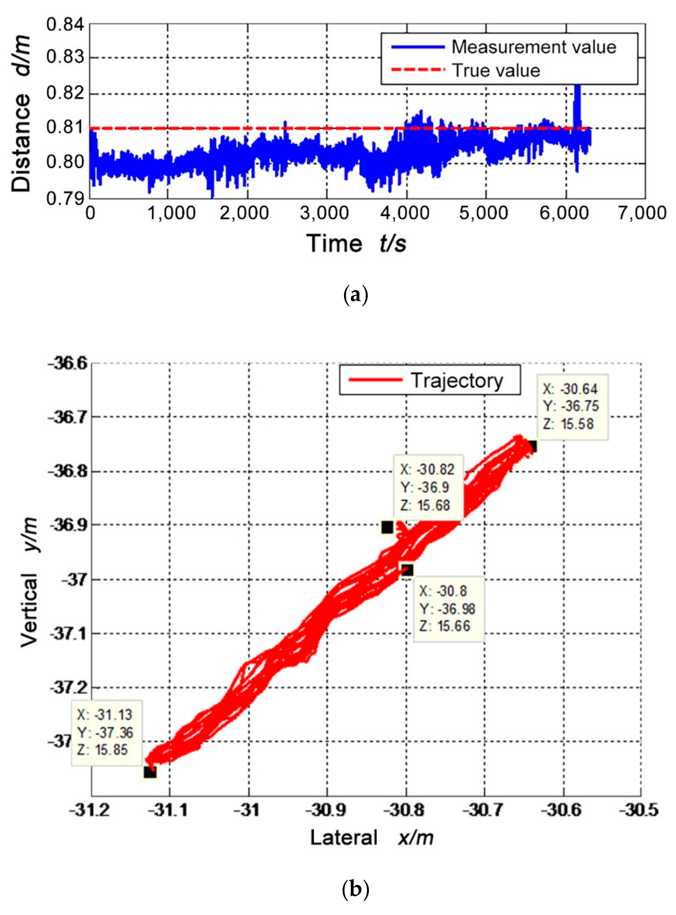
Using the high-precision IMU data and the relative position information obtained by the USV module and UAV module, the extended Kalman filter data is fused, and the obtained position variance is used as the noise estimation of the filter to obtain local high-precision, real-time state estimation results, as shown in
Figure 10.
3.3. Dynamic Analysis of Arresting System
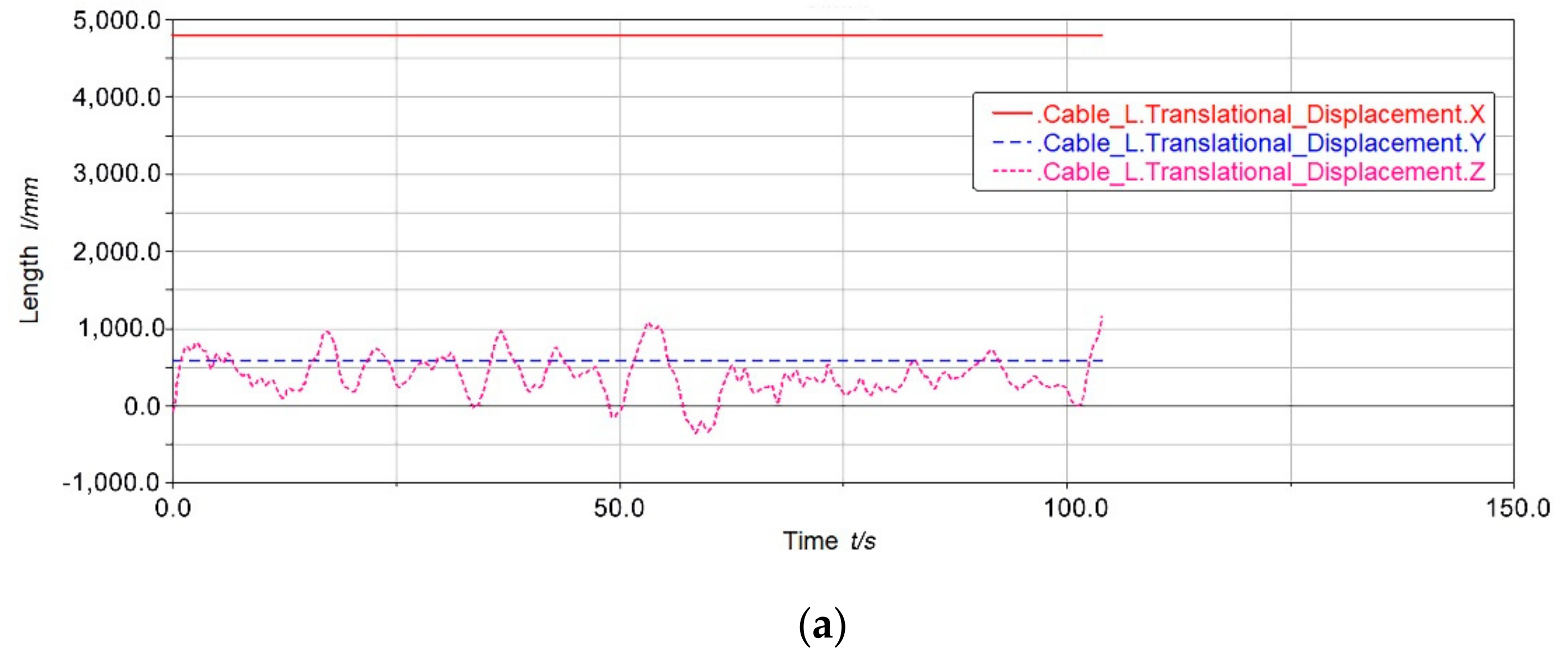
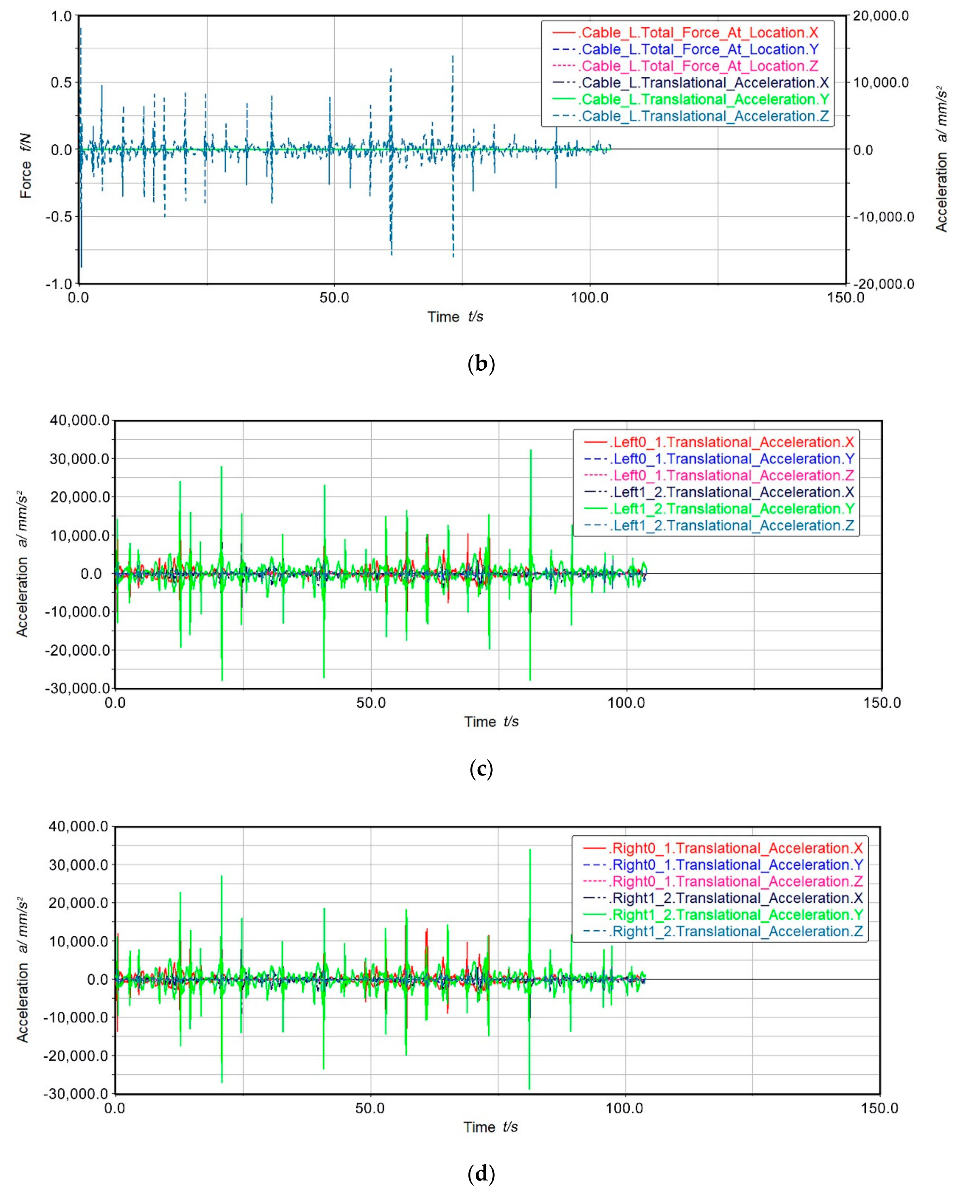
The recovery process of the UAV crashing cable is a nonlinear transient dynamic process, and the recovery mechanism needs to be modeled in the design process. The system’s dynamics simulation can be used to judge the realization of the recovery function, as well as the dynamics and kinematic response characteristics of the UAV during the recovery process.
Based on Lagrange’s equation, a dynamic model consisting of an arresting cable, a damper, a variable stiffness compliance system, and a UAV is established. The dynamics simulation of the UAV from the hook to the recovery process with zero relative speed to the recovery platform is performed. Suppose that the UAV has completed the hook in the initial stage, and the UAV is reduced to a mass point (the lower abdomen hook is designed with a rotational degree of freedom, and the resulting rotational bending moment is small and can be ignored) to simplify the three-dimensional feature.
According to the state of the UAV, the kinetic energy (
), system potential energy (
), and the dissipated energy (
) can be obtained first. According to the Lagrangian variational principle, dynamic differential equations, including design parameters and state parameters, such as the initial state and posture when the UAV hits the cable, the inertia (
) of the blocking mechanism, the damping coefficient (
), and the length of the arresting cable (
) can be solved. Then, the fourth order Runge–Kutta method is used to track its dynamics and kinematics. It can analyze the impact of different parameters on UAV recovery performance, such as maximum acceleration. Take the maximum acceleration of the UAV recovery process as an example. According to the Lagrangian variational principle, the total kinetic energy of the UAV is as follows:
The total dissipated energy of the system is calculated as follows:
The total potential energy of the system is calculated as follows:
where
This is derivable based on the variational principle:
The maximum acceleration of the UAV recovery process is
6. Conclusions
In this study, we designed a fully autonomous recovery system that addresses the problems faced by current autonomous recovery of small ship-based fixed-wing UAVs. Key issues such as active modeling of the UAV–USV heterogeneous platform motion model, accurate estimation of the high dynamic relative motion of heterogeneous platforms, dynamic analysis of the arresting cable system, and compliance control of the manipulator recovery system were investigated, and corresponding methods or solutions were presented. Based on this, a physical simulation platform for the system was developed and verified through physical experiments, which show that our system can achieve full autonomous recovery of small ship-based fixed-wing UAVs with a high success rate in a short period. Thus, our system has laid the foundation for the practical application of heterogeneous unmanned systems consisting of UAVs and USVs in the marine environment.
Next, we will study the stable flight control technology under unconventional initial conditions of the UAV and develop a prototype of the UAV–USV marsupial system consisting of small UAVs and a USV. Moreover, we will conduct application tests to verify the behavioral coordination ability of the UAV–USV marsupial platform under the influence of multiple coupling, strong dynamics, and uncertain factors, such as wind, waves, and currents.

 ,
, 


