Article

Landfill Slope Stability Improvement Incorporating Reinforcements in Reclamation Process Applying Observational Method

1
Institute of Civil Engineering, Warsaw University of Life Sciences - SGGW, 159 Nowoursynowska Str., 02-787 Warsaw, Poland
2
Faculty of Civil Engineering, Silesian University of Technology, 5 Akademicka Str., 44-100 Gliwice, Poland
*
Authors to whom correspondence should be addressed.
Appl. Sci. 2020, 10(5), 1572; https://doi.org/10.3390/app10051572
Submission received: 31 December 2019 / Revised: 14 February 2020 / Accepted: 19 February 2020 / Published: 25 February 2020
(This article belongs to the Section Civil Engineering)

Abstract

:
This paper concerns a case study presenting one of the biggest landfills in Poland that required application of complex engineering works to extend the deposing capacity of the structure. The shear strength parameters of the subsoil and waste material used for analyses were based on geotechnical investigation and were then applied in slope stability analyses of the landfill. For the purpose of safety management of the new development and reclamation plan for the landfill, an observational method was applied to increase the geotechnical safety of the structure. The slope reinforcement methods mainly included the geogrid, geocomposite, and berms construction. However, much of the uncertainty associated with the stability of the geogrid-reinforced slope is related to the time-dependent deformation of geosynthetic materials. For the purpose of changes in the geogrid parameters with time, the samples were excavated from the landfill slope after 20 years of exploitation and analyzed in the laboratory. The tests allowed precise determination of the material properties, changing geometry, and mechanical properties like tensile strength and strain. Obtained results were compared to parameters of the brand-new geogrid samples. The tests indicated only insignificant changes in geosynthetics, physical, or mechanical performance properties, and the slope has not been compromised in its stability or performance.

1. Introduction

Landfill engineering mainly deals with preventing or mitigating the effects of environmental threats and nuisance. One of the major concerns when designing an embankment-type landfill or preparing a reclamation plan is the geotechnical safety of the structure. When analyzing the overall stability of a landfill, the main task is to precisely determine the mechanical and elasticity parameters of the landfill to evaluate potential displacements and to analyze the scenarios of waste-built slope failures [1]. Decomposition of landfill waste and its characteristics depends upon many factors such as waste composition, compaction, initial moisture content, inhibition, rate of moisture transport, amount of oxygen available, changes in a wide range of pH values, temperature, and other factors [2,3]. The rate of chemical and biological reaction in a landfill generally increases with temperature and moisture. Waste decomposition in landfills tends to take place slowly over a very long period of time [1,2,3,4]. Municipal waste deposited on landfills is a highly geotechnical and diverse material, depending on the morphological composition, age, and state of compaction. For all these reasons, when it comes to evaluating or modeling the geotechnical behavior of the entire structure, the task becomes very much challenging. This refers mainly to deformation and slope stability analyses of embankment-type landfills. Due to continuous operation of the landfill, the main challenge in the present study was to control the entire process of geometry engineering to assure full safety of the entire structure. For this purpose, the pioneering solution at that time was the introduction of observational methods as an approach allowing the necessary modifications to a development plan at every stage of the geotechnical work [5,6]. This method allows the introduction of continuous amendments to design solutions during the construction, exploitation, and reclamation process at landfills. At that time, and even nowadays, the approach of applying similar solutions is not usually used for contaminated sites. Predicting the behavior of a landfill body and the subsoil is a very challenging task. It is mainly due to difficulties in the precise determination of waste material parameters and adopting accurate computation models. Observational methods also allow back-analysis to be used to investigate the material properties and perform validations of predicted behavior of the landfill subsoil and structural elements [7]. The present study concerns an old municipal landfill with geometry that needed to be adjusted and engineered due to waste capacity expansion requirements, for a very limited area. For this purpose, a number of slope improvement techniques were used. They mainly involved geosynthetics applications, a dewatering system design, and retaining wall and berm construction. Geosynthetics have recently found wide application in the design and construction of embankment-type landfills. This application has been triggered by the economic and technical advantages that geosynthetics can offer when compared to more traditional materials [8,9,10]. The geogrids used in the construction process should maintain their performance characteristics up to 100 years, according to the standards. Due to the ageing process, present especially at such sites as landfills, the life design of the geogrid would depend on the exploitation time [11,12]. The short-term effects such as installation damage that reduce the maximum tensile strength decreases the allowable tensile strength of the material. A creeping process, aging by oxidation and abrasion, is also of major concern as it results in long-term strength loss [13,14,15,16]. One of the main challenges on landfills is to secure the slope stability. However, given the conditions prevailing at waste landfills, the geosynthetics are exposed to a very hazardous environment. Several ageing or degradation mechanisms can occur in the geosynthetic materials depending on the exposure conditions (time, environment) and polymer used. Due to the varied effects of the surrounding environment (e.g., mechanical stresses by load, changes in a wide range of pH values, and high temperatures), geosynthetic materials can be exposed to different degradation processes, for example, degradation by swelling, thermal degradation, chemical degradation, degradation by extraction, biological degradation, and oxidative degradation [17,18,19,20].
The present paper reports a case study concerning an old municipal landfill located in the capital of Poland, Warsaw. It required the application of a solution to meet the waste deposition demand without expanding the original area. The mechanical parameters of the subsoil and waste material were based on complex geotechnical investigation and laboratory tests and were then applied in landfill slope stability analyses using the limit equilibrium method. For the purposes of safety management for the reclamation process and adopting a new development plan, an approach named observational method was applied to increase the geotechnical safety of the structure during the reclamation process. Such an approach has not been previously presented in the literature for landfill sites. The slope reinforcement methods mainly included the geogrid, geocomposite, and berms. The geosynthetics originally built in were considered as new material that could help solve discussed issues. However, the main unknown of the research was how they would interact with anthropogenic materials over time. The overall idea on the purpose of the study is given in Figure 1.

2. Materials and Methods

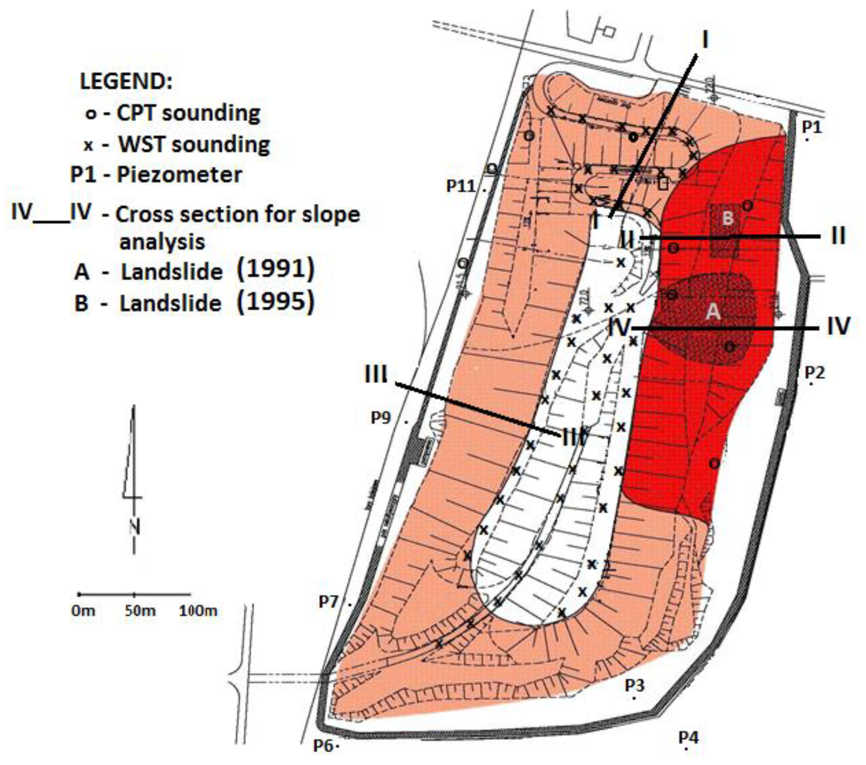
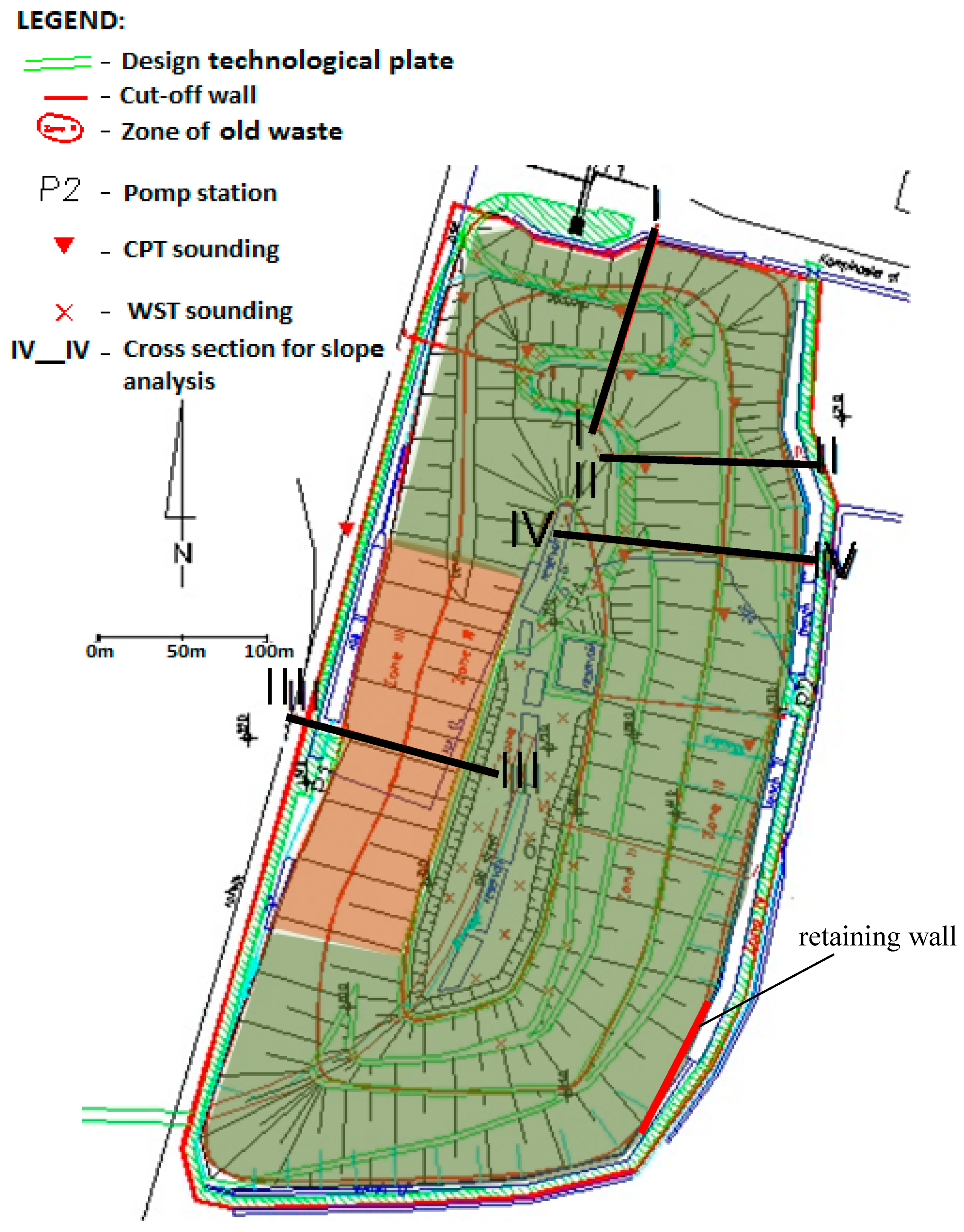
2.1. Site Investigation for Establishing Landfill Waste Properties

In the case of Radiowo landfill, the main challenge was to precisely determine the geotechnical parameters of waste built into the slope so the further stability analyses results could be reliable. For this purpose, the mechanical parameters of waste were investigated by using three main groups of tests. These were back-analyses, trial loading, and geotechnical in situ tests (cone penetrometer test, CPT; weight sounding test, WST; dynamic probe test, DPT). Based on the obtained results, the parameters could be established and adopted for further computation. For back-analysis methods, there were three cross-sections selected and surveyed on the landfill itself. After investigation of the landslide that occurred in the past, by knowing its factor of safety and having a precisely documented slip surface, it was possible to back-calculate the mechanical parameters of the slope-filling material. During the failure, the location of layers of the weakest parameters (investigated by using CPT and WST test) was confirmed. To further investigate the mechanical parameters of waste, there was also a trial embankment constructed, filled with waste, and overloaded with concrete slabs to induce the slope failure so another set of back-calculations for confirming the CPT and WST test results could be performed. Such broad verification of material properties allowed reliable computations of the factor of safety for other slopes on the landfill.
The in situ tests for Radiowo landfill were performed in 1993–1999. The investigation was performed to determine waste mechanical parameters for the stability analysis and settlement prediction, as well as the estimation of bearing capacity for the landfill access road foundation. The other group of field tests was a geotechnical investigation including DPT, WST, and CPT tests [4]. The WST was generally performed in the vicinity of the main road constructed on the landfill body. Tests were repeated when a thickness of waste of 5 m was reached. The results were used for the quality control of the road foundation compaction. The average amount of N20 (number of blows for 20 cm penetration) for fresh waste was 10 and 5 for old waste. The amount of N20 increased twice as much when the disposing waste was separated with sand layers. The CPT investigation reached a depth of approximately 25 m. Based on those results, the effective internal friction angle for waste felt was within the range of φ’ = 25–45°. However, in some particular locations, the values dropped down to φ’ = 20–24°. These values were obtained after having considered waste as non-cohesive soils. The test results confirmed the presence of waste cohesion. The CPT test interpretation for waste, analogically to cohesive soils, gave a total shear strength of τfu = 80 kPa for non-composted and τfu = 90 kPa for municipal waste. The geotechnical parameters of waste material are presented in Table 1.

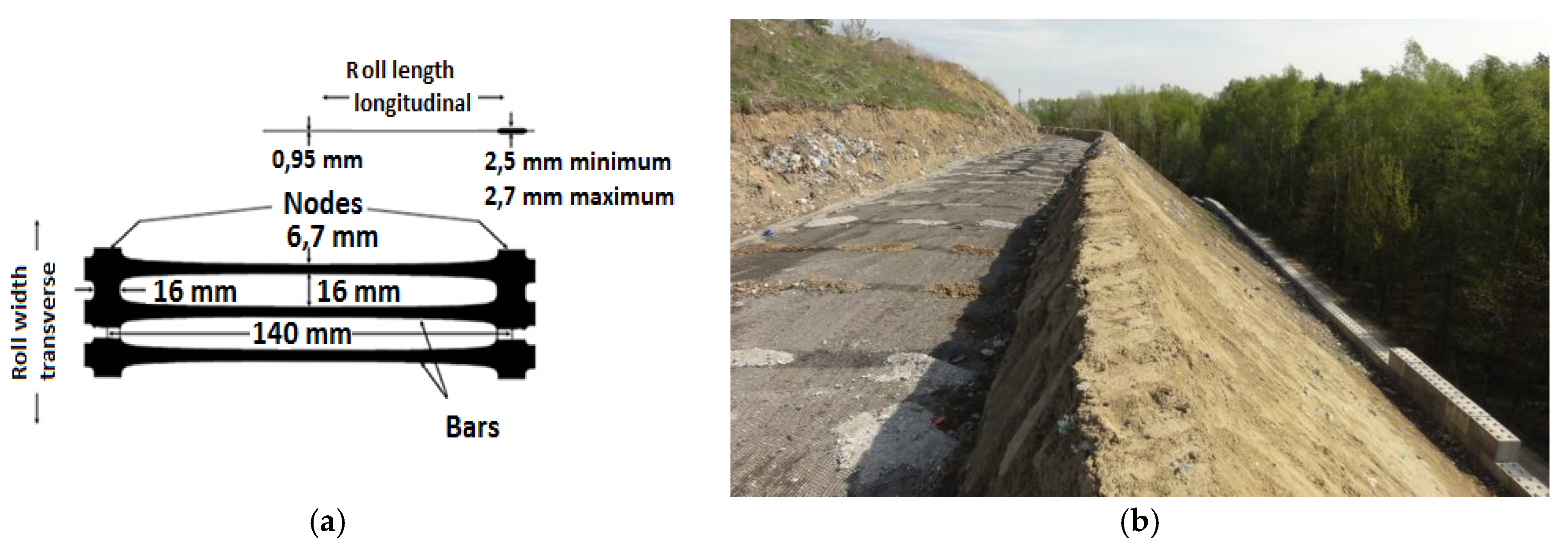
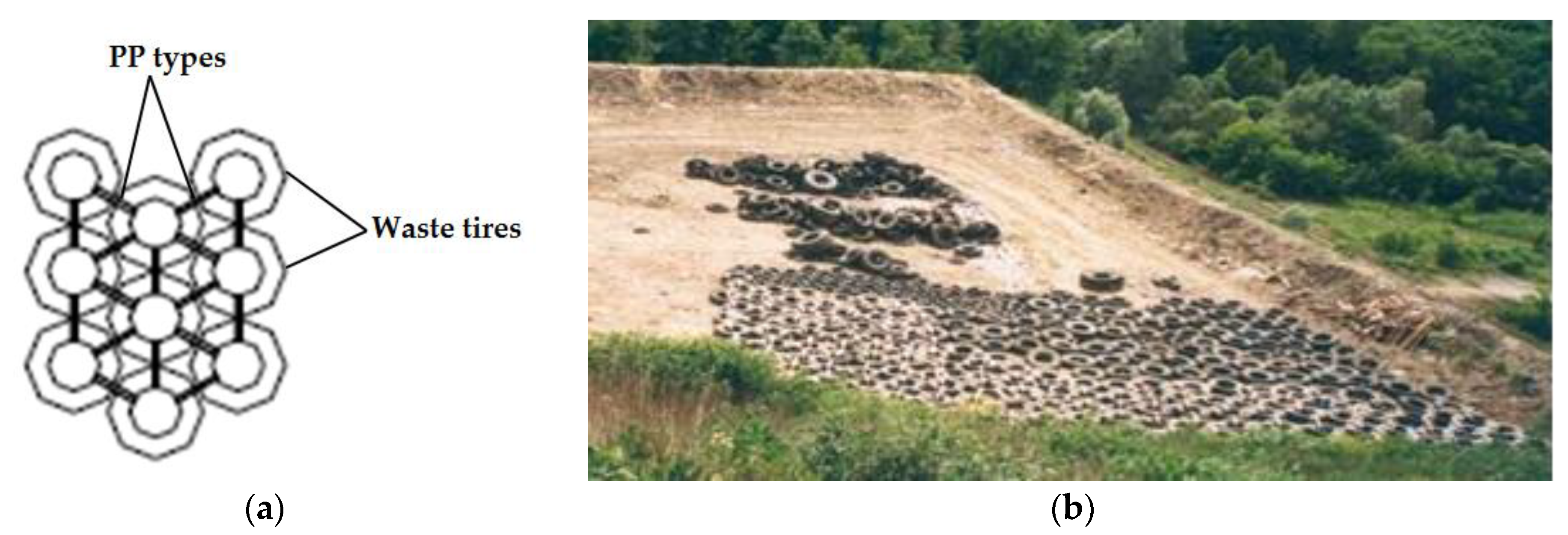
2.2. Geosynthetic Lateral Reinforcements

One of the soil-reinforcing elements used in Radiowo landfill stability improvement is a uniaxial geogrid. It is a material manufactured by punching, reheating, and drawing an extruded sheet of high-density polyethylene (HDPE). The whole process was performed to increase the tensile strength and tensile stiffness of the polymer. The geometry and main mechanical properties of the geogrid used at the landfill site are presented in Table 2 and Figure 2.
In addition, in order to improve the stability of the slopes, a berm was constructed as a geo-composite consisting of a mattress made of used tires. The tires were tied up with PP- polypropylene tape connected with PE- polyethylene clips (Figure 3). In order to ensure the required strength of the connection corresponding to the strength of the tires, 8 coils of tape were used for a single joint. The entire structure (berm reinforced using tires) was used to load the toe of the landfill slope to improve the geotechnical safety.

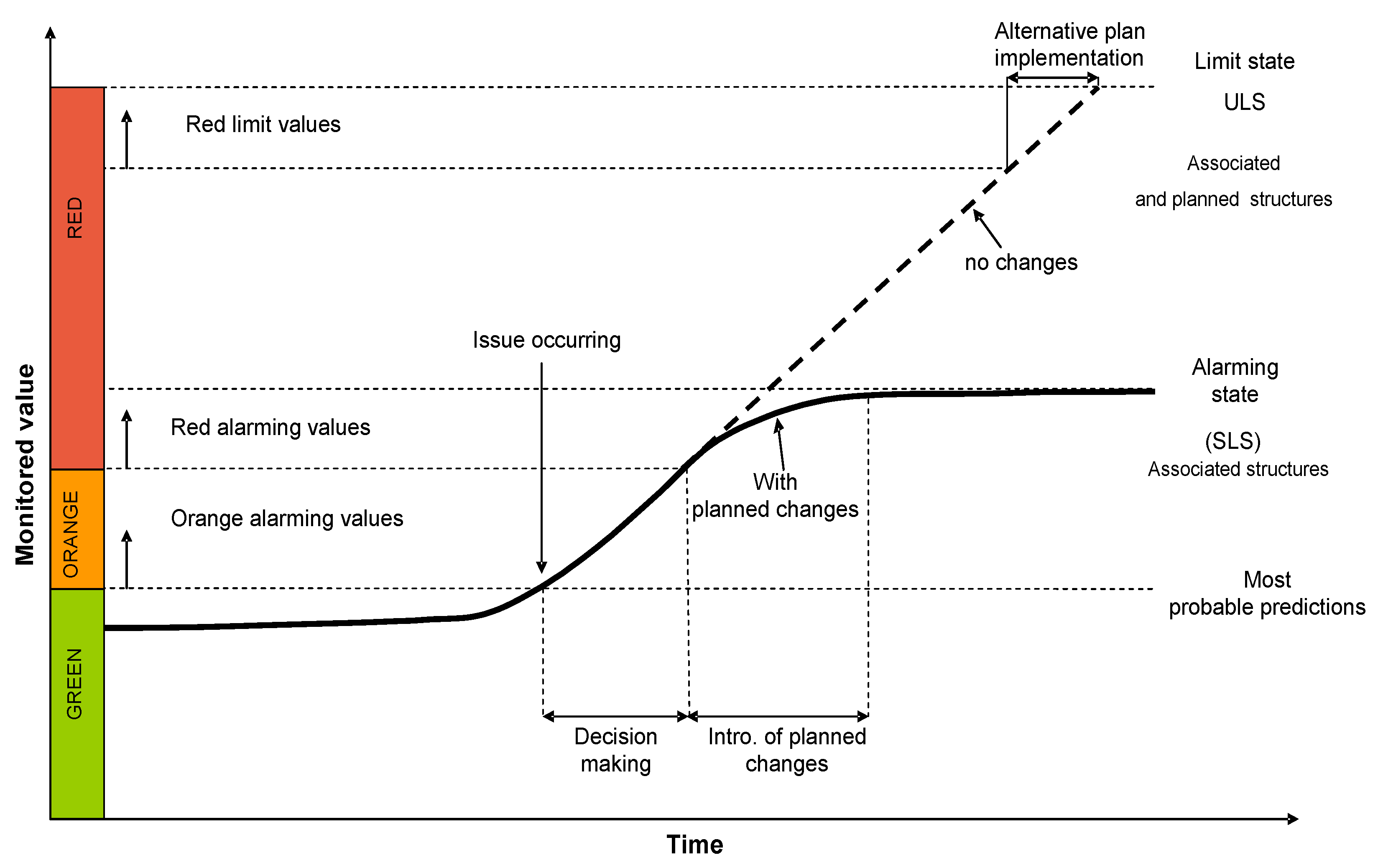
2.3. Observational Method Approach Adopted in the Present Study

The exploitation and reclamation of a landfill is a long-term process that requires applying interdisciplinary approaches. However, the crucial part determining the effectiveness of the process is the geotechnical structures incorporated within the landfill site (namely, reinforcing structures, barriers, cut offs). The landfills can be considered as earth engineering structures filled with anthropogenic material with associated protection systems such as liners, drainage, and reinforcements. The engineering works on a landfill require the application of certain rules when waste layering, compaction, or even reinforcing structures designed for steep slopes on embankment-type landfills. Due to the long-lasting reclamation process and its complexity, so-called observational methods are becoming more popular in landfill engineering practice [5,6]. An observational method in geotechnics is a continuous, controlled, and integrated design process. It is considered an execution process control tool, monitoring system, and a review method allowing the introduction of an initially defined modification during the working plan execution. The objective of the observational method is the reduction of investment expanses with the simultaneous increase in safety level of the investment. The method could be applied in the early stage of design or after completing certain tasks if the benefits derived from its use were identified at earlier stages of the investment process [21]. The observational method is always a combination of a common geotechnical site investigation, theoretical modeling, and plans for unpredicted scenarios. Using only monitoring results, the structure safety is assured to not be enough according to the international standards [22,23]. The key is to identify the potential failure mechanism. The investigation needs to be designed carefully so the state limits are monitored. They always need to be comprehensively conducted and executed in a strict manner.
The effectiveness of the observational method mainly depends on the flexibility of the management system. It is necessary that the alternative plans are validated and applied at every stage of the investment process. Drawing the limit boundaries in the observational method before engineering works execution is a challenging and complex task. It requires the use of sophisticated estimation models depending on the analyzed process. The key factor here is developing an effective control program and comprehensive monitoring. The method, when applied in geotechnical engineering, mainly covers monitoring implementation and setting the boundary levels, and, when exceeded, allows appropriate decisions to be made regarding further stages of the investment. It allows execution works or repetitions of analyses to be improved and amendments to the project to be made. In the observational method, there is a rule of threshold settings. These are the boundaries determining the timescale for taking appropriate action. There are usually two decision-making levels:
(1)
Warning level, indicating the shifts in forecasted values, leaving space for introducing (or not) corrections in the design process,
(2)
Limit level, indicating the shift in forecasted values that requires immediate response and introducing an alternative solution.
In the case of having the warning or limit levels exceeded, or any other threats appearing, the traffic lights system could be adopted to describe each phase of the work or decision-making stages. The system is presented in Figure 4. The different colors indicate different threat levels.
(1)
Green; the measured values are lower than the alarming ones (orange); it is a safe stage (level 1),
(2)
Orange; the values exceed admissible levels, more data control is required here, and there is a little risk of failure (level 2),
(3)
Red; it is considered after the values exceeded alarming levels; to prevent serviceability limit states, immediate action needs to be taken (level 3).
Such an approach was used in the present study, of which the results are presented and discussed. The method is a novel solution when it comes to landfill reclamation processes and gives an opportunity to provide a much safer process of managing contaminated sites.

3. Results and Discussion

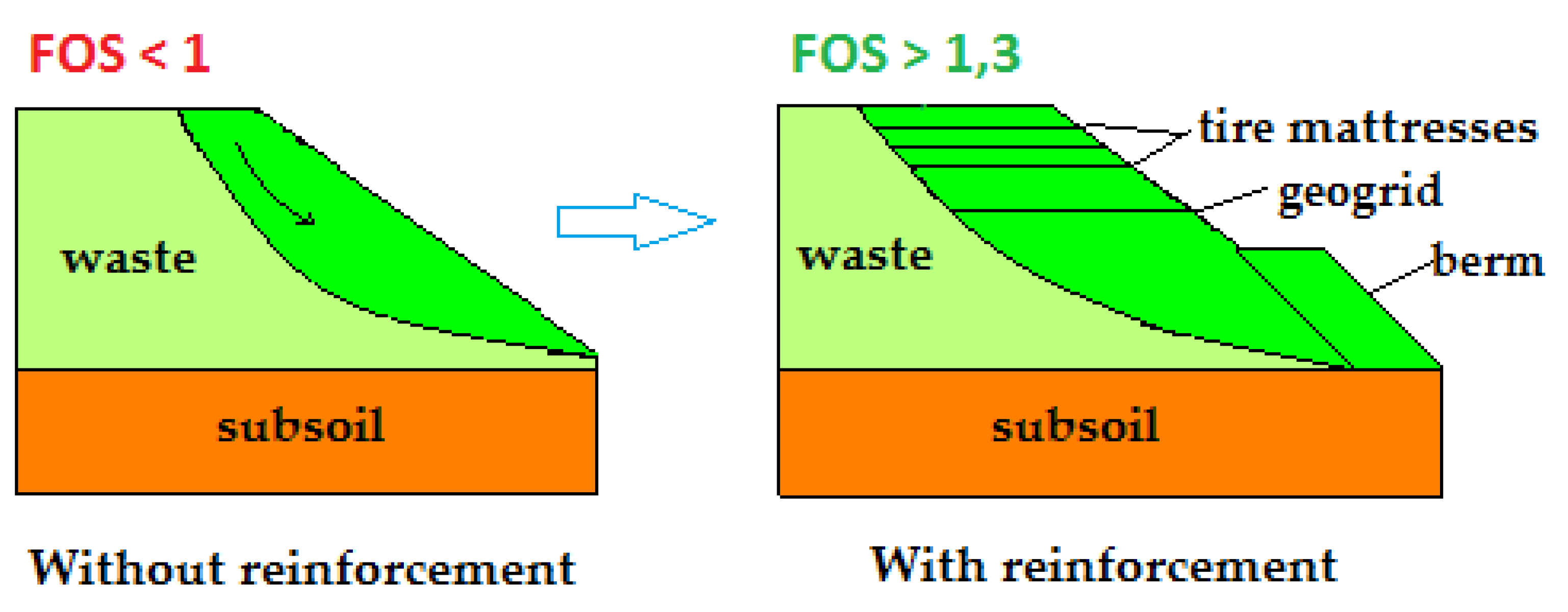
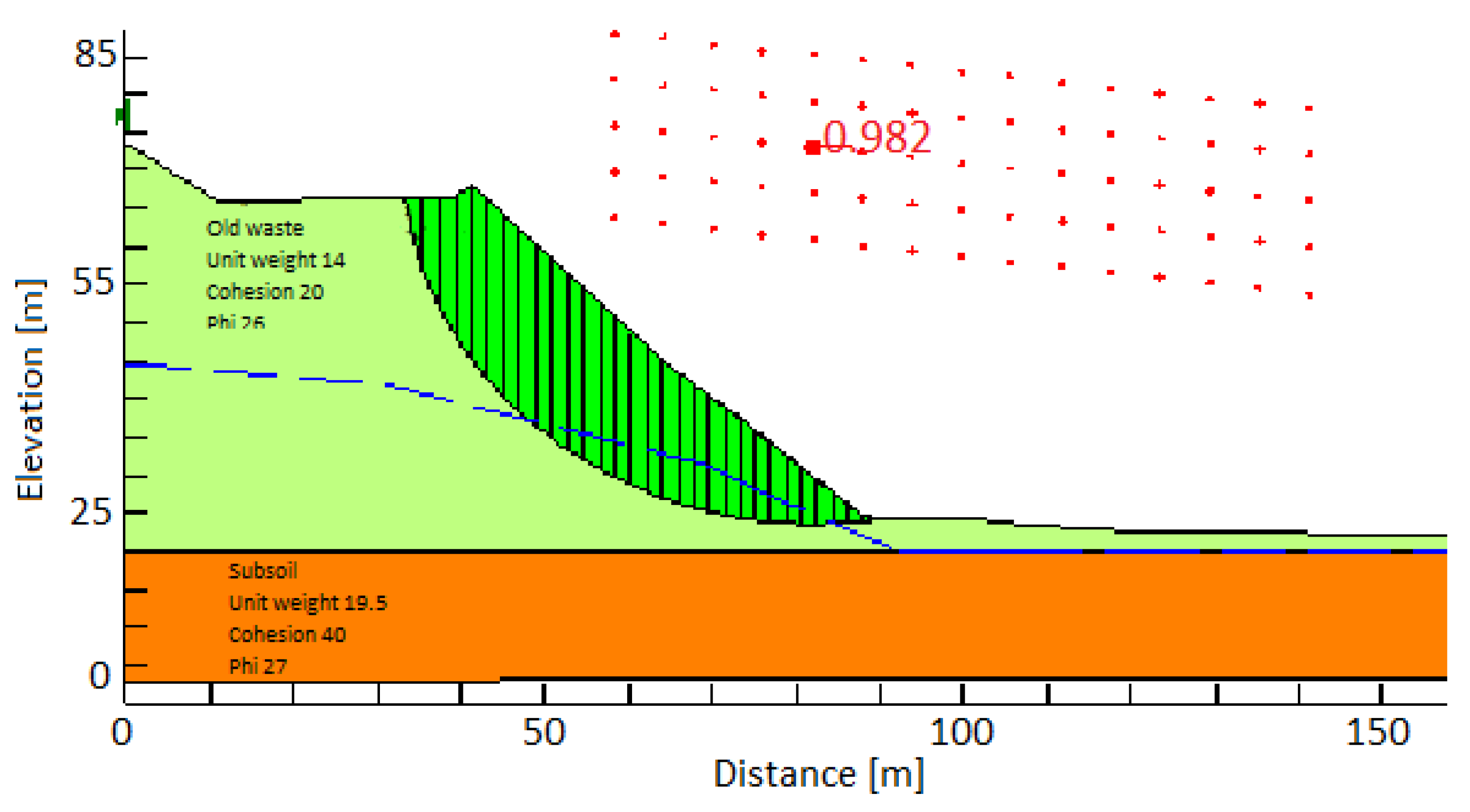
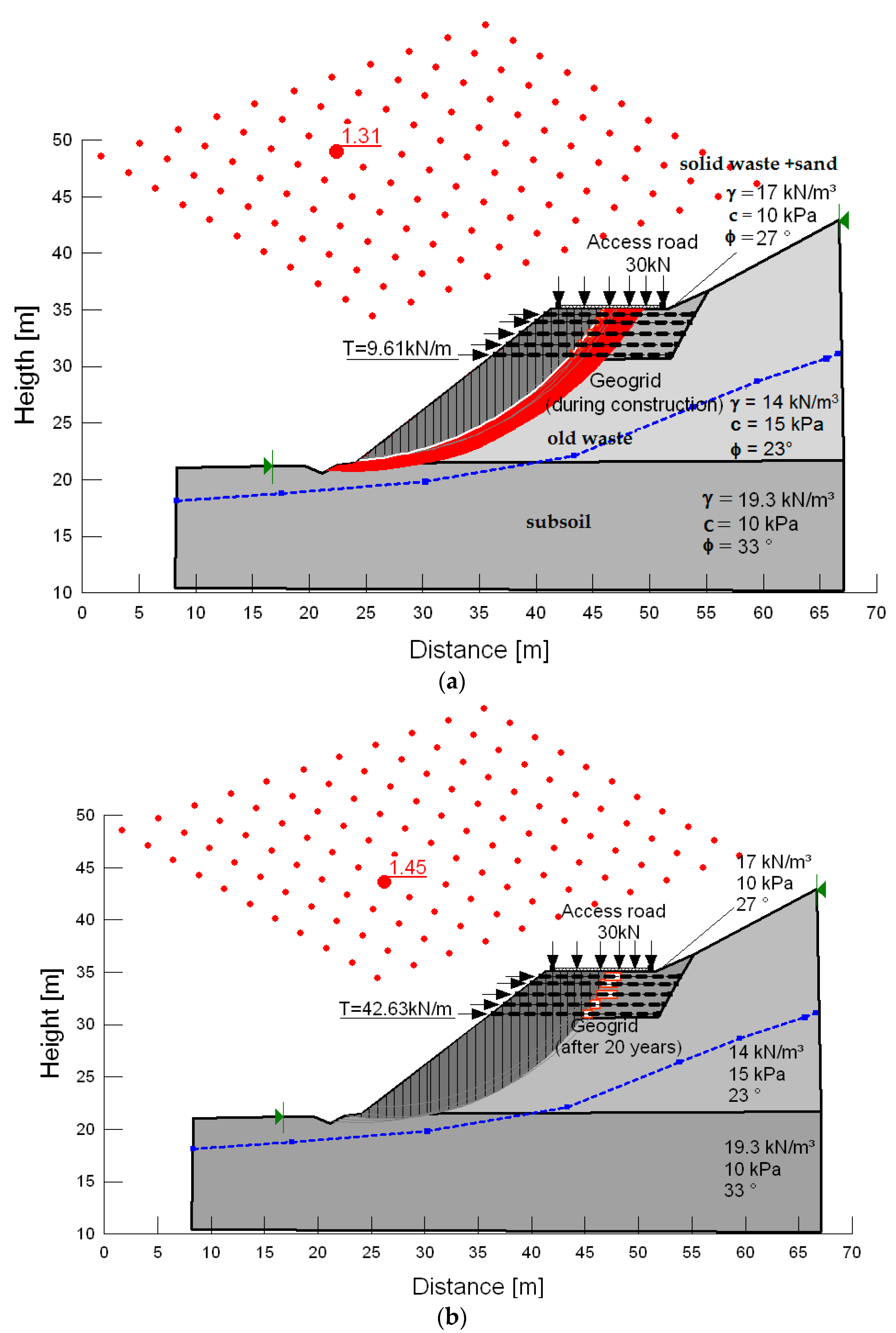
3.1. Slope Stability Analyses Incorporating Reinforcements

For the purpose of determining the locations of most probable slope failures on the landfill, there was a network of benchmarks installed at the site. The network helped in defining failure endangered zones, for which the approach of the observational method was applied. It allowed the analysis of the vertical and horizontal displacement measurements of the landfill body during exploitation time [24,25]. This type of monitoring system allowed the evaluation of the behavior of all slope movement influenced by different groundwater flow conditions, and engineering works execution. The observations revealed a higher increment in horizontal displacement than vertical displacement. This means the increase in slopes steepness, which, in the near future, could induce severe slope failure. Such behavior was confirmed by numerical analyses conducted with the use of limit equilibrium method (LEM) [26]. The result for a selected cross-section is presented in Figure 5.
The monitoring and modeling of horizontal displacements gave precise information on which slopes should be engineered or reinforced, to assure the overall stability. In 1993, reclamation works on the landfill began. They included safety improvements in terms of engineering the landfill body. To reinforce the slope and to improve the bearing capacity of the access road to the landfill, a retaining wall was also constructed (south-east landfill slope on Figure 6 and Figure 7). By the further carving of the slope, installation of a horizontal uniaxial HDPE geogrid was also proposed. The reason for such heavy modifications was that on the southern slope, the space was very limited due to land ownership issues. The main objective of the reclamation works was to allow as much disposal of municipal waste on the landfill as possible. However, due to the composition of the ballast waste, which did not meet the specific filling material requirements, a new method of compaction and slope filling was adopted. The reason for that was to basically make the material useful for landfill access road construction. The works were also executed by applying the observational method approaches. Based on the waste mechanical characteristics and compaction difficulties, the final decision on mixing the waste with well-graded material was made.
As mentioned previously for the slope stability analyses, the observational method approach of a traffic lights system was adopted. Such an approach had not been considered in any other case studies available in the scientific literature at that time. To classify the safety of landfill slopes, three different levels of computed factors of safety (FOSs) were set:
(1)
Green color - FOS > 1.3, the slope is safe (risk level 1), does not require further action (continuous monitoring and maintenance is required).
(2)
Orange color - FOS = 1.3–1.1, alarming condition (risk level 2), stability uncertain, extensive monitoring required, reinforcements application depending on results.
(3)
Red color - FOS < 1.1, possibility of exceeding ultimate limit state (risk level 3), it is necessary to adopt an alternative plan and immediate changes in the project.
Based on the FOS results presented in Table 3 it is clear that the safety condition on most of the landfill slopes before the reclamation was classified as alarming or exceeded. It was confirmed by the number of local slope failures and cracks observed in the past on the slopes (eastern slope on cross-section III especially—Figure 6). After the reinforcements were introduced, almost in every cross-section, the safety was increased to “green” levels. The results can be seen in Figure 7, where the displacement monitoring and numerical computations were used to present the conditions of the landfill body. After the reinforcement works were accomplished, the calculated factors of safety felt were in a safe zone (Figure 7). The western slope (cross-section II) indicates an FOS value of 1.27, but according to observation, the slope is stable, with well-established vegetation cover and no signs of potential failure to occur in the future.

3.2. Mechanical and Physical Parameters Analyses of Geogrids

This section focuses on the mechanical and physical parameters of HDPE geogrids used for the reinforcement of slopes in an old sanitary landfill. The analyzed HDPE geogrid was installed more than 20 years ago (in 1993). The geogrid was excavated in November 2013 and was then tested by using several laboratory methods [27,28,29,30,31].
Three samples of geogrids were collected from the landfill after 20 years of exploitation, and the sample size had a width of approximately 1.0 m and length of about 1.20 m. The samples were excavated from the upper layer of the structure, which consists of five layers and is located at the access road to the landfill.
Physical and mechanical compositional tests have been performed on the specimens, which were provided by the manufacturer and also on exhumed geogrid samples.
The physical and mechanical test results are reported as arithmetic averages with standard deviation and are listed in Table 4. The tests were performed on multiple specimens: For physical properties testing, 10 samples were used, and to measure mass per unit area, only one sample was used.
For the mechanical properties measurement, five samples were tested. The ultimate tensile strength falls in the range from 42.63 to 52.55 kN/m and the strain in maximum load ranges from 5.28% to 7.41%. The average values of the ultimate tensile strength for aged samples are 48.92 kN/m. Given that the geogrid is mostly exposed to mechanical factors during installation, the value is assumed to be high [32]. The comparison of laboratory tests of exhumed geogrid samples (Table 4), using typical values given by the geogrid supplier, indicates that the change in average value of the tensile strength was from 55 to 48.92 kN/m and the average value of elongation at maximum force was from 11.2% to 6.4%. The physical test results (i.e., rib and cross-machine direction (CMD) bar thickness, aperture size values) show no significant change in dimensional properties throughout the 20 years of service.
For the purpose of estimating the influence of geogrid strength changing over time on the landfill slope, analyses of local stability were performed. There were two scenarios considered. One when the slope was reinforced with a newly built-in geogrid and another for conditions where the geogrid was exploited on the landfill for 20 years. The analyses (Figure 8a,b) were performed by using LEM incorporating lateral reinforcements [33,34]. The slope stability analyses incorporating reinforcements used the approach of the pull-out resistance, which can be specified if passive resistance is the dominant stress transfer mechanism. Passive resistance refers to the development of bearing-type stresses on relatively stiff members of the reinforcement that are situated normal to the direction of pull-out. The method of calculation applied Bishop’s method of slices. Incorporating reinforcements during the calculations is achieved by employing reduction factors.
For the first case (Figure 8a), the strength parameters for the geogrid were applied as recommended by the manufacturer: 9.61 kN/m long-term strength [35]. For the latter scenario, the factor of safety was computed based on the actual geogrid tensile strength, determined in a laboratory using samples excavated from the slope after 20 years of its exploitation (Figure 8b). The geotechnical parameters of the filling material were adjusted and increased due to compaction and sand mixing of the waste. In this particular location, an access road to the landfill crest was designed. To increase the bearing capacity of the road, the waste material was mixed with a sand fraction and heavily compacted using appropriate equipment. New parameters were as follows: For the landfill access road sub-base: γ = 17 kN/m3, φ = 27°, c = 10 kPa; and for waste filling the slope: γ = 14 kN/m3, φ = 23°, c = 15 kPa. The parameters of the subsoil remained unchanged as there was no deep soil reinforcements applied. The computed factors of safety for the two considered cases were FOS = 1.31 and 1.45, respectively, for the geogrid of nominal tensile strength of 9.61 kN/m and laboratory-tested value of 42.63 kN/m. Such a significant difference is caused by applying different security coefficients in the past, when no standards for design were used. According to the applied safety regulation, FOS = 1.45 is sufficient and meets the “traffic light” standards used for the purposes of the present study.

4. Conclusions

The characteristics of a landfill structure and the long-term process of reclamation create suitable conditions for application of the observational method. The monitoring and displacement analyses, and determination of the geotechnical parameters of waste material, allow successful application of such an approach especially in the safety management of such demanding sites. The proposed method was used here to expand the volume of the landfill and the exploitation time. The engineering works at the site allowed the volume of the landfill to be extended by as much as 800,000 m3, which increased the capacity to a further 7 years for waste disposal at the site. The study revealed that the assessment of geotechnical stability threats could be performed using a “traffic light” system, determining the safety levels depending on the factor of safety results. The use of the observational method allowed the comprehensive recognition of processes occurring at the landfills and can lead to achieving expected results if the method is applied appropriately. Such an approach is not commonly used in the reclamation process, which makes a significant contribution to current environmental geotechnics and land restoration and remediation, especially for landfill sites.
The present study also showed a variety of geosynthetic applications in landfill engineering. The use of such materials in severe operating conditions showed their usefulness and applicability. It was proven that application of geosynthetic materials in this case was an appropriate solution.
HDPE geogrid parameters analyzed in the laboratory tests, after 20 years of continuous service in the municipal waste landfill, showed only minor parameter changes compared to the brand-new material. No significant deterioration of the geogrid’s mechanical parameters was observed. The tensile strength mechanical damage reduced by no more than 10%–20%. Such tests are quite unique, as it is not a common practice to excavate geotextile reinforcement samples after 20 years of service. The slope stability analyses for the reinforced landfill slope applying the modified geogrid tensile strength and geotechnical parameters of the filling material were presented. The design revealed that the FOS increased as much as 10% after 20 years of landfill exploitation due to the increase in real resistance of the geogrid measured in the laboratory.
The reinforcements using geogrids with layers of anthropogenic material as a result gave a significant improvement of over-stability of the slopes. Such approach has been widely used also as a reinforcement component on number of environmentally valuable, or very much challenging sites [36]. The major challenge in this particular case, which was the expansion of landfill capacity, was successfully accomplished. By using waste material for construction purposes, meeting the environmental and sustainable development European standards was possible. All the observations, both field and laboratory tests, did not show the negative impact of anthropogenic soils on the properties and behavior of geogrids used in the present study. However, further observations and investigation need to be continued.

Author Contributions

Conceptualization, E.K.; methodology, E.K., A.K. and P.O.; software, E.K. and P.O.; validation, P.O.; formal analysis, E.K. and J.K.; investigation, E.K., A.K., J.K. and P.O.; resources, E.K.; data curation, A.K., J.K. and P.O.; writing—original draft preparation A.K. and P.O.; writing—review and editing, A.K. and P.O.; visualization, A.K. and P.O.; supervision E.K.; funding acquisition, E.K. All authors have read and agreed to the published version of the manuscript.

Funding

This research received no external funding.

Conflicts of Interest

The authors declare no conflict of interest.

References and Notes

  1. Reddy, K.R.; Hettiarachchi, H.; Gangathulasi, J.; Bogner, J.E. Geotechnical properties of municipal solid waste at different phases of biodegradation. Waste Manag. 2011, 31, 2275–2286. [Google Scholar] [CrossRef] [PubMed]
  2. Feng, S.J.; Gao, K.W.; Chen, Y.X.; Li, Y.; Zhang, L.M.; Chen, H.X. Geotechnical properties of municipal solid waste at Laogang Landfill, China. Waste Manag. 2017, 63, 354–365. [Google Scholar] [CrossRef] [PubMed]
  3. Park, S.; Kim, W.; Lee, J.; Baek, Y. Case Study on Slope Stability Changes Caused by Earthquakes—Focusing on Gyeongju 5.8 ML EQ. Sustainability 2018, 10, 3441. [Google Scholar] [CrossRef] [Green Version]
  4. Yang, R.; Zengguang, X.; Junrui, C.A. Review of characteristics of landfilled municipal solid waste in several countries: Physical composition, Unit Weight, and Permeability Coefficient. Pol. J. Environ. Stud. 2018, 27, 2425–2435. [Google Scholar] [CrossRef]
  5. Spross, J.; Johansson, F. When is the observational method in geotechnical engineering favourable? Str. Saf. 2017, 66, 17–26. [Google Scholar] [CrossRef]
  6. Nicholson, D.; Tse, C.M.; Penny, C.; O’Hana, S.; Hana, S.; Dimmock, R. The Observational Method in Ground Engineering: Principles and Applications; CIRIA Report No. 185; Construction Industry Research and Information Association: London, UK, 1999. [Google Scholar]
  7. Gunturi, V.R. (Ed.) Analysis and Modeling of Landfill Failure; Technical Report; Indian Institute of Technology: Dehli, India, 2018. [Google Scholar]
  8. Vaverkova, M. Impact assessment of the municipal solid landfill on environment: A case study. Acta Sci. Pol. 2019, 18, 11–20. [Google Scholar] [CrossRef]
  9. Koda, E. Stability conditions improvement of the old sanitary landfills. In Proceedings of the 3th Internatonal Congress on Environment Geotechnics, Lisboa, Portugal, 7–11 September 1998. [Google Scholar]
  10. Pancar, E.B.; Akpınar, M.V. Comparison of Effects of Using Geosynthetics and Lime Stabilization to Increase Bearing Capacity of Unpaved Road Subgrade. Adv. Mat. Sci. Eng. 2016, 2016. [Google Scholar] [CrossRef] [Green Version]
  11. Geosynthetics—Guidelines for the Assessment of Durability; ISO/TS 13434; International Organization for Standardization: Geneva, Switzerland, 2008.
  12. EBGEO. Recommendations for Design and Analysis of Earth Structures Using Geosynthetic Reinforcements; Ernst & Sohn Verlag: Berlin, Germany, 2011. [Google Scholar]
  13. Koda, E.; Szymanski, A.; Wolski, W. Behavior of geodrains in organic subsoil. In Proceedings of the Conference on Soil Mechanics and Foundation Engineering, Rio de Janeiro, Brazil, 13–18 August 1989; Volume 2, pp. 1377–1380. [Google Scholar]
  14. Koda, E.; Szymański, A.; Wolski, W. Field and laboratory experience with the use of strip drains in organic soils. Can. Geotech. J. 1993, 30, 308–318. [Google Scholar] [CrossRef]
  15. Hufenus, R.; Rüegger, R.; Flum, D.; Sterba, I.J. Strength reduction factors due to installation damage of reinforcing geosynthetics. Geotext. Geomembr. 2005, 23, 55–75. [Google Scholar] [CrossRef]
  16. Carneiro, J.R.; Almeida, P.J.; Lopes, M.L. Resistance of high-density polyethylene geonets against chemical ageing. In Proceedings of the 6th International Congress on Environmental Geotechnics, New Delhi, India, 7–12 November 2010. [Google Scholar]
  17. Rowe, K.; Islam, M.Z.; Hsuan, Y.G. Leachate chemical composition effects on OIT depletion in an HDPE geomembrane. Geosynth. Int. 2008, 15, 2. [Google Scholar] [CrossRef] [Green Version]
  18. Rowe, R.K.; Ewais, A.M.R. Ageing of exposed geomembranes at locations with different climatological conditions. Can. Geotech. J. 2015, 52, 326–343. [Google Scholar] [CrossRef] [Green Version]
  19. Kiersnowska, A.; Koda, E.; Fabianowski, W.; Kawalec, J. Effect of the Impact of Chemical and Environmental Factors on the Durability of the High Density Polyethylene (HDPE) Geogrid in a Sanitary Landfill. Appl. Sci. 2017, 7, 22. [Google Scholar] [CrossRef] [Green Version]
  20. Kay, D.; Blond, E.; Mlynarek, J. Geosynthetics Durability: A Polymer Chemistry Issue. In 57th Canadian Geotechnical Conference 5th Joint Cgs/Iah-Cnc Conference; Geological Survey of Canada: Quebec, QC, Canada, 2004; Volume 4, pp. 1–14. [Google Scholar]
  21. Patel, D.; Nicholson, D.; Huybrechts, N.; Maertens, J. The observational method in geotechnics. In Proceedings of the XIV European Conference on Soil Mechanics and Geotechnical Engineering, Madrid, Spain, 24–27 September 2007. [Google Scholar]
  22. Koda, E. Landfill Stability under Reclamation and Pollutant Transport Using the Observational Method; Treatises and Monographs. No 384; Warsaw University of Life Sciences Press: Warsaw, Poland, 2011. [Google Scholar]
  23. Koda, E.; Grzyb, M.; Osiński, P.; Vaverkova, M.D. Analysis of failure in landfill construction systems. Matec. Web Conf. 2019, 284, 03002. [Google Scholar] [CrossRef]
  24. Baiocchi, V.; Quintilio, N.; Martina, T.; Giampaolo, S.; Maria, A.; Domenica, C. UAV for monitoring the settlement of a landfill. Eur. J. Rem. Sens. 2019, 52, 41–52. [Google Scholar] [CrossRef]
  25. Cuartas, M.; López, A.; Pérez, F.; Lobo, A. Analysis of landfill design variables based on scientific computing. Waste Manag. 2018, 71, 287–300. [Google Scholar] [CrossRef]
  26. Gao, W.; Bian, X.C.; Xu, W.J.; Chen, Y.M. Storage capacity and slope stability analysis of municipal solid waste landfills. J. Perf. Constr. Fac. 2018, 32, 04018036. [Google Scholar] [CrossRef]
  27. CEN/TC 189 Geosynthetics (Committee), & ISO/TC 221 Geosynthetics (Committee). (2005). Geosynthetics—Test Method for the Determination of Mass Per Unit Area of Geotextiles and Geotextile-related Products. International Organization for Standardization.
  28. ISO. PN-EN ISO 9863-1: Geosynthetics—Determination of Thickness at Specified—1: Single Layers; CEN: Brussels, Belgium, 2005. [Google Scholar]
  29. PN-EN ISO 10319: ISO, E. (2008). Geosynthetics—Wide-width tensile test. PN-EN ISO, 10319.
  30. Bhowmik, R.; Datta, M.; Shahu, J.T. Pullout Behaviour of Geosynthetics—A Review of Laboratory Testing Techniques. In Ground Improvement Techniques and Geosynthetics; Springer: Singapore, 2019; pp. 219–227. [Google Scholar]
  31. Sun, Y.; Xu, H.; Gu, P.; Hu, W. Application of FBG sensing technology in stability analysis of geogrid-reinforced slope. Sensors 2017, 17, 597. [Google Scholar] [CrossRef] [PubMed] [Green Version]
  32. Pant, S. Stability Analysis of Geosynthetic Reinforced MSW Landfill. Management 2016, 31, 2275–2286. [Google Scholar]
  33. Mokhtari, M.; Rafsanjani, A.A.H.; Shariatmadari, N. The effect of aging on the compressibility behavior and the physical properties of municipal solid wastes: A case study of Kahrizak landfill, Tehran. Environ. E. Sci. 2019, 78, 519. [Google Scholar] [CrossRef]
  34. Salimi, K.; Ghazavi, M. Soil reinforcement and slope stabilisation using recycled waste plastic sheets. Geomech. Geoeng. 2019, 1, 1–12. [Google Scholar] [CrossRef]
  35. Tensar. The Long-Term Performance of Tensar Geogrids; Tensar/Nelton LTD: Blackburn, UK, 1990. [Google Scholar]
  36. Osiński, P.; Dobrzelewski, B.; Koda, E.; Król, P. Slope stability analyses incorporating soil improvement methods for valuable urban area. In Geotechnics for Sustainable Infrastructure Development; Springer: Singapore, 2020; pp. 803–808. [Google Scholar]
Figure 1. Lateral reinforcements of landfill slope to improve the factor of safety (FOS).
Applsci 10 01572 g001
Figure 2. (a) Geometry of uniaxial geogrid and (b) landfill slope reinforced with geogrid.
Applsci 10 01572 g002
Figure 3. (a) Scheme of tire junction with PP- polypropylene tape, and (b) tire mattresses built in the landfill slope.
Applsci 10 01572 g003
Figure 4. Observational method approach used in the present study.
Applsci 10 01572 g004
Figure 5. Slope stability analyses for a bare slope, using limit equilibrium method (LEM) indicating low value of FOS.
Applsci 10 01572 g005
Figure 6. Geotechnical safety assessment based on “traffic lights” approach applying observational method framework—no slope reinforcements.
Applsci 10 01572 g006
Figure 7. Geotechnical safety assessment based on “traffic lights” approach applying observational method framework—with landfill slopes reinforcement.
Applsci 10 01572 g007
Figure 8. Slope stability analyses for (a) newly built geogrid of nominal tensile strength of 9.61 kN/m, and (b) geogrid after 20 years (measured tensile strength of 42.63 kN/m).
Applsci 10 01572 g008
Table 1. Shear strength parameters for municipal solid waste obtained from diver’s approaches.
Waste MaterialΓ [kN/m3]Φ [°]C [kPa]Testing Methods
Solid waste9.02025trial loading, CPT, WST
Solid waste + sand12.02523trial loading, CPT, WST
Old waste14.02620back-analysis, CPT, WST
Table 2. Mechanical properties of uniaxial geogrid.
Mechanical Properties
Tensile strength at 2% strain (kN/m)19.0
Tensile strength at 5% strain (kN/m)33.5
Peak tensile strength (kN/m)55
Yield point elongation (%)11.2
Table 3. The results of the stability analysis for the Radiowo site according to Bishop method [22].
Slope Cross-SectionReinforcementFOS
Bishop Method
Without ReinforcementWith Reinforcement
Northern -IInclination change (geogrid)1.041.36
Western -IIBerm (tire mattress)1.141.27
Eastern -IIIBerm1.061.36
Further Western -IVBerm and retaining wall1.181.33
Table 4. Mechanical and physical characteristics of the geogrid determined based on laboratory tests.
TestsParametersSpecific StandardNew Sample 1Exhumed Samples
Mean ValueStandard Deviation
PhysicalMass per unit area (g/m2)PN-EN ISO 9864 [27]500532-
Aperture Size (mm)-140140.241.56
Rib Thickness (mm)PN-EN ISO 9863-1 [28]0.950.970.0078
CMD Bar Thickness (mm)2.5 ÷ 2.72.700.0640
MechanicalMean Tensile Strength (kN/m)PN-EN ISO 10319 [29]5548.924.20
Mean Strain at Maximum Load (%)11.26.400.89
1 manufacturer information.

