Article

A Flux-Controllable NI HTS Flux-Switching Machine for Electric Vehicle Applications

Center for Scientific Instrumentation, Korea Basic Science Institute, Daejeon 34133, Korea
*
Author to whom correspondence should be addressed.
Appl. Sci. 2020, 10(5), 1564; https://doi.org/10.3390/app10051564
Submission received: 13 February 2020 / Revised: 21 February 2020 / Accepted: 24 February 2020 / Published: 25 February 2020
(This article belongs to the Special Issue Superconductor Technologies and Their Applications)

Abstract

:
This paper deals with a flux-controllable NI HTS flux-switching machine (FSM) for electric vehicle (EV) applications. In a variable-speed rotating machine for EVs, such as electric buses, electric aircraft and electric ships, an electric motor capable of regulating the flux offers the advantage of constant output operation. In general, conventional HTS rotating machines have excellent flux-regulation performance, because they excite an HTS field coil. However, it is difficult to ensure any flux-regulation capabilities in HTS rotating machines using HTS field coils that apply the no-insulation (NI) winding technique, due to the inherent charge and discharge delays in these machines. Nevertheless, the NI winding technique is being actively researched as a key technology for the successful development of HTS rotating machines, because it can dramatically improve the operational stability of HTS field coils. Therefore, research to implement an HTS rotating machine with flux-regulation capabilities, while improving the operating stability of the HTS field coil using the NI winding technique, is required for EV applications. In this paper, we propose an HTS rotating machine with a flux switching structure, a type of topology of a rotating machine that is being actively studied for application to the electric motors used in EVs. The proposed HTS flux-switching machine (FSM) uses NI field coils, but additional field windings are applied for flux regulation, which enables flux control. In this study, an NI HTS field coil was also fabricated and tested because the characteristic resistance value should be used for the design and characteristic analyses of machines which utilize an NI coil. The simulation model used to analyze the flux-regulation performance capabilities of the NI HTS FSM were devised based on the characteristic resistance values obtained from a charging test of the fabricated NI HTS field coil. This study can provide a good reference for further research, including work on the manufacturing of a prototype NI HTS FSM for EV applications, and it can be used as a reference for the development of other HTS rotating machines, such as those used in large-scale wind power generation, where flux-regulation capabilities are required.

1. Introduction

Currently, electric vehicles (EVs) are regarded as good candidates for decreasing environmental pollution by reducing the use of fossil fuels [1,2,3,4,5,6,7]. Accordingly, there has been rapid progress in the creation of electric vehicles. An EV, also known as an electric vehicle, is a type of transportation which uses electric motors for propulsion in place of a conventional propulsion system, such as an internal combustion engine (ICE). EVs can include electric cars, electric buses, electric trucks, electric trains, electric aircraft, electric scooters and even electric ships. Motion in EVs can be provided by wheels or propellers driven by traction motors, or in the case of railway vehicles, by linear motors.
Two types of electric motors are commonly used for vehicle applications: The induction motor (IM), and the permanent magnet synchronous motor (PMSM), and it is generally known that IMs have lower rated torque and efficiency levels compared to PMSMs. In general, PMSMs are more efficient, and for this reason electric vehicles commonly use these types of electric motors. However, because a PMSM uses constant magnetic flux generated by PMs, the flux can only be regulated by means of an armature reaction flux control by a converter. This decreases the machine efficiency, because it significantly increases the winding losses. While PMSMs have employed innovative technologies, it is not easy to increase the electric motor output power any further.
As an advanced technology for electric motors, researchers have made progress on the development of high-temperature superconducting rotating machines. Because superconducting wires can handle high-density current flows well, compared to copper wire, it is possible to manufacture a coil capable of generating a very high magnetic field, even with a low number of windings using superconducting wires. Therefore, by applying superconducting coils to electrical machines such as a motor and generator, it is possible to develop electrical machines with high efficiency and high output power levels. Accordingly, many researchers have attempted to apply superconducting motors to EVs, and the applicability of superconducting motors has been largely verified [8,9,10,11,12,13,14,15]. However, for the practical application of superconducting motors to EVs, the operating stability and reliability must be improved. Superconductors can exhibit superconductivity only under critical environmental conditions, such as those with a critical current, critical temperature and critical magnetic field, and superconductivity is lost when this condition deviates for any reason. If this phenomenon, called quenching, occurs, superconductors gain electrical resistance, which can lead to Joule heating and damage. In particular, such damage can be a serious problem in high-temperature superconducting (HTS) wires, given their relatively slow normal zone propagation velocities. Therefore, in order to apply superconducting coils wound with HTS wiring to electrical machines, it is very important to protect the HTS coils from the quenching phenomenon. The approach known as the no-insulation (NI) winding technique is a viable quench-protection method for HTS coils [16,17,18,19,20,21,22,23,24,25]. The NI winding technique involves the fabrication of coils without insulation materials between the turns. Figure 1 shows the quench-protection mechanism of the NI winding technique. In this figure, Iop is the operating current flowing through the coil. For an HTS coil with turn-to-turn insulation, even if a hot spot occurs due to a partial quench, the current flows continuously through the hot spot, meaning that Joule heat is continuously generated. On the other hand, an NI coil without turn-to-turn insulation has a self-protection mechanism, in that it bypasses the current to the adjacent turns automatically when the HTS coil is partially quenched. Given that the electrical resistance of the superconducting layer under the normal operation condition is nearly zero, the current flows only to the superconducting layer. However, when a hot spot caused by local quenching occurs, electrical resistance occurs at the local portion. Therefore, the current flows through the stabilizer layer constituting the superconducting wire, and it is thus bypassed. As a result, NI coils can be protected from quenching without complicated quench detection schemes and/or protection devices, simplifying these HTS coil systems [16,17,18,19,20,21,22,23,24,25]. However, the NI HTS coil is associated with an intrinsic charging/discharging delay phenomenon. The charging/discharging delay phenomenon increases as the coil inductance increases, and the contact resistance between winding turns decreases. Figure 2 shows a circuit model of the NI HTS coil. In this figure, the portion indicated by the light blue background represents the simplified equivalent circuit model of the NI HTS coil. As indicated by this circuit model, when the current is charged or discharged, the current in the NI HTS coil is divided into a spiral direction (winding direction) and a radial direction (contact direction between winding turns). The division ratio of the current is determined by the ratio of the azimuthal impedance value, which is in turn determined by the coil inductance and the current charge/discharge rate to the radial impedance value due to the characteristic resistance. The magnetic field generated by the coil stems from the current flowing in the spiral direction. Therefore, if the coil inductance is large, the current flowing through the contact becomes large, such that the delay phenomenon during the charge and discharge of the magnetic field becomes very large. Therefore, in order to develop a robust electric motor using an NI coil, the effects by these charge and discharge delays should be considered.
Various researchers have attempted to apply HTS coils to electrical machines, such as motors and generators [26,27,28,29,30,31,32,33]. Specifically, these studies are more actively carried out in relation to electrical rotating machines, which require high output power levels, such as those used for wind power generation and in electric vehicle applications. Thus far, most studies on the application of superconducting coils to electrical rotating machines have mainly used an air-core type of structure, which does not use iron cores. In electrical rotating machines with an air-core structure, the superconducting field coils are positioned in the rotor to create a rotating field. Therefore, in the rotating field coil structure, the cooling system and the excitation system are inevitably complicated, and require a highly reliable design [31,32,33,34]. In the rotor excitation machine, the field current must be fed through the slip ring and brushes, and the cooling system requires dynamic seals for cryogenic transfer coupling. On the other hand, electrical rotating machines, such as a flux-switching machine (FSM), a homopolar machine and a Vernier machine, use iron cores, but it is possible to realize a robust machine, because they have stationary field coil structures. The cooling system and excitation system for the field coils in machines with a stationary field coil structure can be made simpler than those in a machine with a rotating field coil structure. For this reason, research on the application of HTS field coils to electrical rotating machines with a stationary field coil structure has been active. In particular, the FSM with stationary HTS field coils is becoming more attractive, given its advantages of a robust rotor and a reliable machine structure [32,33,34,35,36,37,38].
However, while the FSM has a robust rotor structure, the protection issue related to HTS field coils should be considered, as in other HTS rotating machines. The NI winding technique can serve as a solution in this case. However, the FSM uses a ferromagnetic core to create a switched type of flux, which makes the inductance of the HTS field coil very large. Therefore, the intrinsic charging and discharging delay effect of the NI coil becomes very large. This can also develop into a technical problem during the application of an electrical rotating machine requiring flux-control capabilities. Therefore, in order to apply an NI HTS field coil to a flux-controllable FSM, a separate winding is required for flux regulation.
In this paper, the structure of an NI HTS FSM capable of flux control is proposed. An FSM applying the proposed structure was designed, and its flux regulation characteristics were analyzed through a transient motion analysis. To do this, an NI HTS field coil was fabricated and tested, and the characteristic resistance of the fabricated NI HTS field coil was calculated from the charging time constant through a current charging test of the coil. It was confirmed that the flux-control capability cannot be achieved by applying only the NI HTS fields for field excitation. Therefore, in order to realize the flux-control capabilities of the NI HTS FSM, a separate winding is required for flux regulation.

2. Machine Structure Operating Principle and Design of the Flux-Controllable NI HTS FSM

2.1. Machine Structure of the Flux-Controllable NI HTS FSM

Figure 3 shows the topology of the flux-controllable FSM proposed in this paper. It is composed of a rotor core, armature windings, NI HTS field coils, and additional field windings. All windings, including the field windings, are located in the stator core. Accordingly, the machine has a robust rotor structure. A ferromagnetic material is used for the stator and the rotor core. Three-phase armature windings are considered, and the armature windings are placed in each stator slot, with each winding connected in series. The NI HTS field coils generate the main magnetic flux during the steady-state operation, and additional field windings are used for flux regulation. Unlike conventional rotor excitation machines, the FSM has a doubly salient structure, with the field coils placed in the U-shaped iron core of the stator. In this machine, the rotor core has a simple laminated iron core which has salient poles. The flux direction of each field coil is opposite between the adjacent field coils.

2.2. Operating Principle of the Flux-Controllable NI HTS FSM

Figure 4 shows the principle of flux switching in the NI HTS FSM. With the doubly salient topology, the magnetic field generated by the NI HTS field coils always traverses the path with the minimum magnetic reluctance at positions where the rotor poles and the stator teeth are aligned to each other. At the rotor position shown in Figure 4a, the rotor pole aligns with one of two stator teeth, around which an armature winding is wound, and the magnetic flux that is linked in the armature winding, that exits the rotor pole and enters the armature winding. When the rotor core rotates until another rotor pole aligns with the right part of the doubly salient pole of the stator, the magnetic flux goes out of the armature coil and into the rotor pole, maintaining the same amount of flux linkage, while reversing the polarity, thus ‘switching’ the flux. Clearly, as the rotor core rotates, the flux linkage in the armature windings will change periodically, inducing back-EMF.
Figure 5 represents the flux regulation principle of the flux-controllable FSM. In this machine, the flux-regulation capability is provided by additional field coils wound around the U-shaped doubly salient pole. Figure 5a shows the path of the main magnetic flux generated by the NI HTS field coil. Because the rotor tooth is aligned to the left of the doubly salient pole of the stator, the main magnetic flux forms a clockwise loop with the rotor tooth and the stator. Figure 5b presents the path of the magnetic flux generated by the additional field coil for flux regulation. The flux is generated by the additional field coil marked in yellow in the figure, and the flux also flows in the opposite direction when the direction of the field current changes. As the magneto-motive force (MMF) generated from the additional field coil increases, the flux-regulating effect is enhanced. If the direction of the magnetic flux generated by the additional field coil is identical to the direction of the main magnetic flux, the total magnitude of the flux linkage in the armature windings increases, and vice versa. Figure 5c shows an example of negative regulation, during which the amplitude of the flux linkage in the armature windings decreases.

2.3. Design of the Flux-Controllable FSM

In this study, a three-phase FSM with a rated output power of 20 kW, and a rotation speed of 1000 rpm, was considered. The design was carried out through the following process [32,33].
  • The design specifications of the NI HTS FSM, in this case the output power, flux regulation ratio and phase, are determined.
  • The maximum radius rr,max and length lmax of the rotor are calculated considering rotor material’s mechanical properties, using Equations (1) and (2), respectively.
    r r , m a x = 4 σ y i e l d / ( ( 3 + v ) ρ Ω 2 )
    l m a x = π 2 / k Ω E I / ρ S
  • The slot pitch is calculated based on the pole pitch and the numbers of slots. The number of conductors also are calculated using Equation (3).
    S s l o t = S C u n 0 / β = I 0 n 0 / ( J C u β ) = d s l o t w s l o t
  • The dimensions of the armature conductor and the slot are determined by Equation (4).
    d C u = 2 d s l o t β / n 0 , w C u = w s l o t β / 2
  • The tangential stress in the rotor is calculated using the rotor dimension and the torque via Equation (5).
    σ F tan = T / ( 2 π r 2 l )
  • The required air-gap field density, B0, is then calculated by Equation (6).
    B 0 = 2 π σ F tan ( 2 r ) / ( I S n 0 q cos φ )
  • Based on the required flux regulation ratio and B0, the NI HTS field coil and the additional field winding are designed by means of FEM under a no-load condition.
  • The cryostat for the NI HTS field coil is designed based on the HTS field coil and other thermal loads. The thermal loads of the cryostat are calculated by the equations below [39,40,41].
    Q C L = ( P C L l C L I 2 / A C L k C L A C L ( T H T L ) / L C L ) 2 + 2 I ρ C L k C L ( T H T L )
    Q K = N L A L k L ( T H T L ) / L L
    Q R = σ ( T H 4 T L 4 ) / ( ( 1 ε H ) / ε H A H + ( 1 / ε L + 2 N / ε N N ) / A L )
    Here, QCL, QK, and QR are the thermal loads from the conduction heat transfers by a pair of current leads, the leading-in tubes for the signal lines, and the radiation heat transfer.
  • Characteristic analyses of the deigned machine are carried out in the form of a transient motion analysis, using a commercialized FEM software package.
In this design, an NI HTS field coil was considered for field excitation. Therefore, the characteristic resistance, RC, of the NI HTS field coil is required as a design parameter. For this reason, an NI HTS field coil was fabricated to obtain an RC value. The RC value can be calculated from a charging time constant (τ) by a charging test. Figure 6 shows the NI HTS field coil fabricated in this study. The HTS coil was fabricated using 2G HTS wire with a 12 mm width. It has a double-layered structure with 40 winding turns. Both the effective length and width of the G10 bobbin for the NI HTS coil are 600 mm and 150 mm, respectively. Table 1 shows the specifications of the NI HTS field coil. To determine the characteristic resistance of the fabricated NI HTS field coil, the current charging test was carried out in liquid nitrogen. Figure 7 shows the normalized central magnetic field after current charging at 100 A, with a cryogenic Hall sensor used to measure the magnetic field. After the power supply current reached the target current of 100 A, the magnetic field relaxes over time while holding the current. The field increases logarithmically to approximately 25 mT at 600 s. This outcome indicates that the fabricated NI HTS field coil is affected by the charging delay phenomenon. The typical method for calculating RC in NI HTS coils is to use a decay time constant after a sudden discharge of the power supply current. However, RC for the straight section in a racetrack coil depends on the Lorentz force induced by the excitation current. Because the Lorentz force dissipates as the coil current is instantly decreased to zero, RC is not at all affected by the Lorentz force during a sudden charge [32,42]. Therefore, it is more appropriate to calculate the RC of the NI HTS racetrack coil using the charge time constant. The charging time constant, τ, can be defined as the time interval between B1 and B2 in Figure 7, where B1 is the magnetic field density at the moment when the power supply current is fully charged, and B2 is the sum of B1 and B, which is 0.63 between B1 and a fully charged level.
In Figure 7, the charging time constant (τ) is 89.34 s. The RC value of the coil calculated from the charging time constant is 145 μΩ. Here, L and τ are the coil inductance and the time constant, respectively. Figure 8 shows the measured results of the magnetic field distribution in the NI HTS field coil measured at an excitation current of 100 A. For this measurement, a field mapper with a three-axis motor for sensor movements was used. Considering the charging delay phenomenon of the NI HTS field coil, the magnetic field distribution measurement was performed after 800 s. As indicated in the graph, the central magnetic field generated from the NI HTS field coil at an excitation current of 100 A is 25 mT, and the magnetic field density increases toward the coil winding part.
Based on the aforementioned design process, an NI HTS FSM with a 12-tooth stator was initially chosen. Table 2 presents the design parameters of the NI HTS FSM. A liquid nitrogen cryostat, a vacuum-layered cryostat with a pair of current leads, a liquid nitrogen inlet, a liquid nitrogen outlet, and leading-in tubes, were designed. In order to account for the radiation heat loss, multi-layer insulation (MLI) in the vacuum layer was considered. According to Equations (7)–(9), the total heat loss for each cryostat was calculated and found to be approximately 15 W when three layers of MLI were inserted into the vacuum space. Figure 9 shows the designed LN2 cryostat.

3. Characteristic Analysis of the Flux-Controllable NI HTS FSM

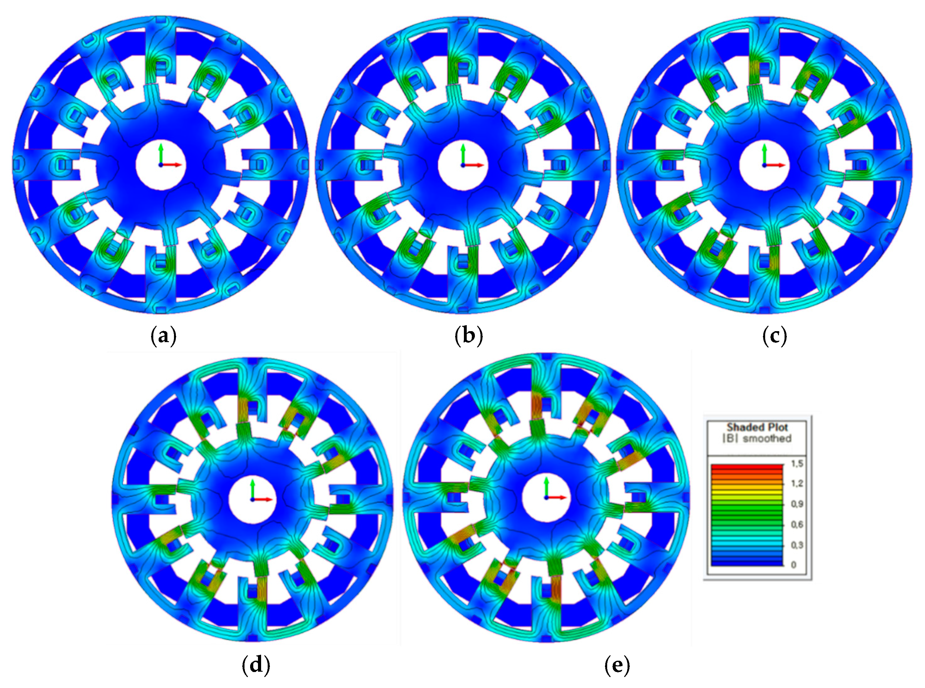
3.1. Field Distribution of the Proposed FSM

In this study, the operating characteristics of the designed NI HTS FSM were analyzed by a combination of the finite element method (FEM) and an electrical circuit analysis. The electrical circuit model was devised based on the simplified circuit model shown in Figure 2. The RC value in the electrical circuit model was calculated from the current charging test of the NI HTS coil. Simulations were performed using FEM software, and the electrical circuit was modeled using a circuit modeler, and was simulated by interworking with the electromagnetic analysis, as shown in Figure 10. In this model, the azimuthal resistance of the HTS coil is assumed to be zero. Figure 11 presents the simulation results of the current charging characteristics of the NI HTS field coil under a 100 A field current with a ramping rate of 1 A s−1. The charging time constant, τ, can be calculated from the time interval between I1 and I2 in Figure 11, as in NI HTS field coil test, because the magnetic field density is proportional to the coil current. Here, I1 is the coil current at the moment when the power supply current reaches the target, and I2 (66.48 A) represents the sum of I1 and I, which is 63% (57.08 A) between I1 (9.40 A) and a fully charged coil current (100 A). The value of τ is 608 s. The coil current is fully charged approximately 9500 s after the excitation current reaches the target. Therefore, the initial time for the simulations of the designed NI HTS FSM in the steady-state condition was set to 10,000 s, considering a full charge of the field current. Figure 12 shows the magnetic flux vector at the rotor position of 0 degrees and 15.75 degrees 10,000 s after the field current reaches the target of 100 A.
The simulation results show that the polarity of the magnetic flux applied to the armature winding changes as the rotor moves. Figure 13 shows the air-gap flux density distributions due only to the excitation of the NI HTS field coils. The local maximum value of the air-gap flux density appears at the position where the stator tooth is fully overlapped with the rotor pole. The local maximum value directly results in the maximum flux of the armature winding A1, and thus is more representative than the absolute maximum value [43]. Therefore, flux regulation can be achieved effectively by adjusting the local maximum value.

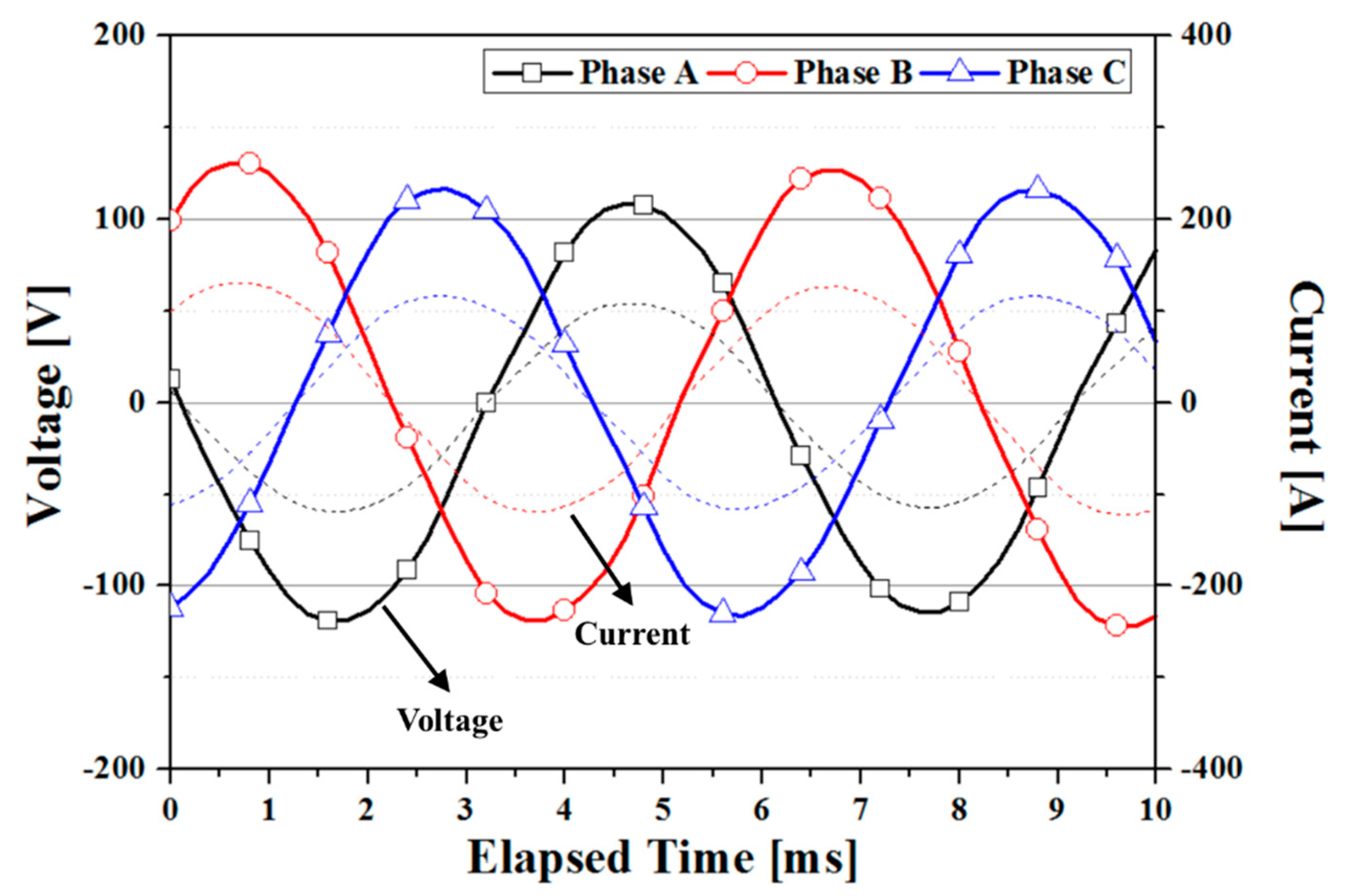
3.2. Operating Characteristics of the Proposed FSM Due Only to NI HTS Field Coil Excitation

In this study, the operating characteristics of the NI HTS FSM were analyzed when excited only with the HTS field coil. Figure 14 presents the flux linkage waveform of the three-phase armature windings. The excitation current of the NI HTS field coil in this analysis is 100 A, and the rotation speed of the rotor is 1000 rpm. In this graph, the x-axis represents the elapsed time 10,000 s after the coil current reaches 100 A. As shown in Figure 14, the flux linkage waveforms are nearly sinusoidal, and the peak value of the flux linkage is close to 0.6 Wb. Figure 15 shows the no-load voltage waveforms of three-phase armature windings. The peak value of the no-load voltage is approximately 770 V. The no-load voltage waveforms exhibit harmonics components due to the lower saturation degree and the rough comparison to conventional machines. The roughness is due to the shield effect of the NI coils. Figure 16 shows the waveforms of the phase voltage and line current in the unit-load condition. The current and voltage waveforms are nearly sinusoidal. From the data shown in Figure 16, it is confirmed that the output power is 20 kW.

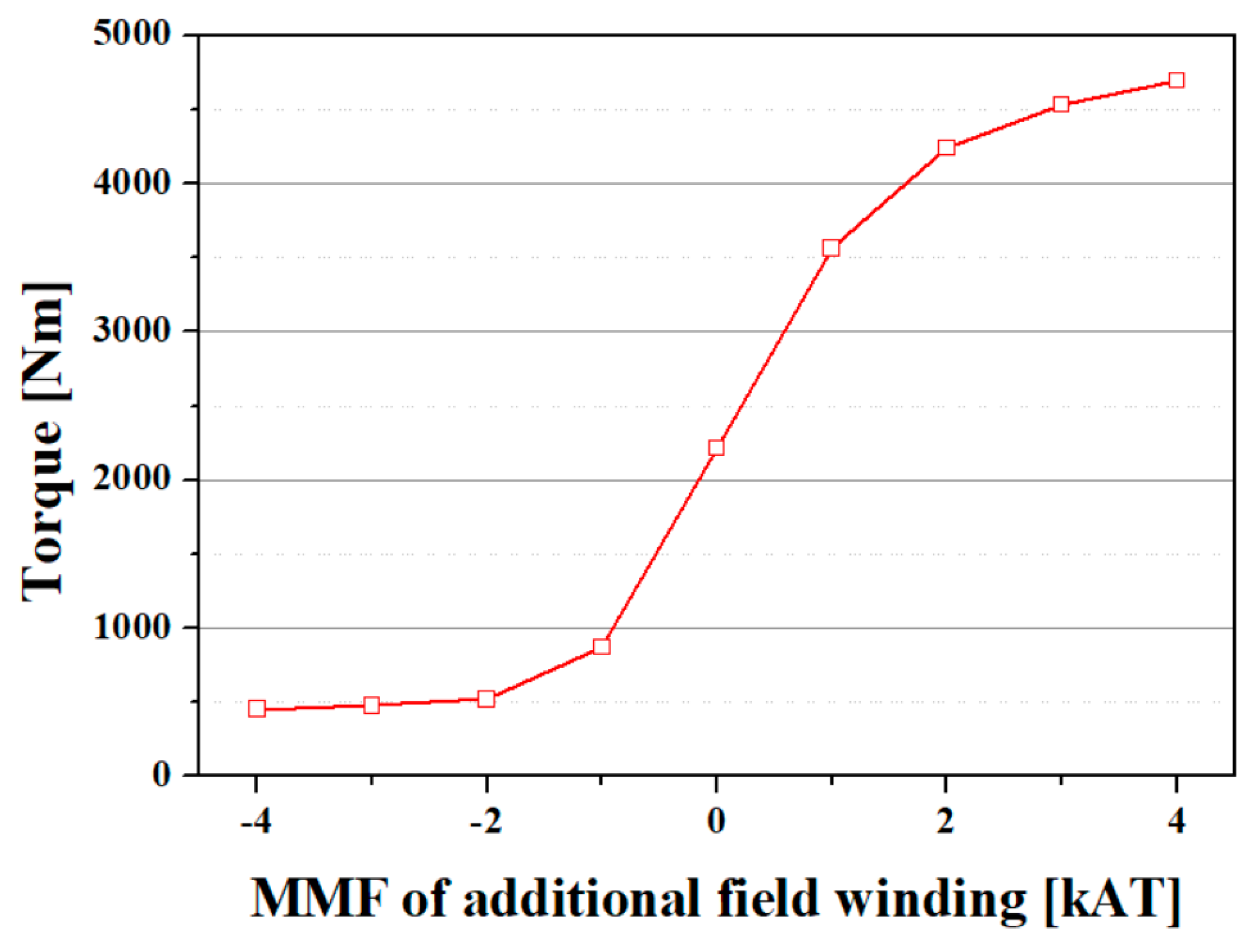
3.3. Flux-Regulation Characteristics of the Proposed FSM

The flux-regulation characteristics were analyzed by means of a transient motion analysis. With the FEM, the no-load magnetic field distributions and flux contours of the proposed machine with different MMF levels of the additional field windings were analyzed. Figure 17 shows the magnetic field distributions according to the MMF of the additional field windings. In this analysis, the excitation current of the NI HTS field coil was maintained at 100 A, while the MMF of the additional field winding was changed. Figure 17c presents the magnetic field distribution and flux contour under only NI HTS field coil excitation. Figure 17a,b show the field distributions with negative regulation current levels of 20 A and 10 A, respectively. Correspondingly, Figure 17d,e show the field distributions with positive regulation current levels of 20 A and 10 A. These figures show that as the regulation current increases, the magnitude of the magnetic field density in the FSM also increases.
Figure 18 shows the flux linkage of the phase C armature winding under different regulation current levels. The regulation current was maintained at zero until 14 milliseconds, and the regulation current was applied to the additional field winding after 14 milliseconds. By controlling the regulation current, the flux linkage of the armature winding can be regulated. When the NI HTS field coils and additional field windings work together, a flux-regulation operation is achieved. Figure 19 compares the no-load voltage waveforms under different regulation modes at 1000 rpm. For solely the NI HTS field coil excitation mode, the peak value of the no-load voltage is approximately 770 V. The peak values in the maximum negative regulation current, and the positive regulation current, are 410 and 980 V, respectively. By applying MMF of −20 kA∙T, the amplitude of the no-load voltage can be reduced by nearly 53%, from 770 V to 410 V. By applying MMF of 20 kA∙t, the amplitude of the no-load voltage can be increased by 27%, from 770 V to 980 V. Figure 20 and Figure 21 correspondingly show the phase voltage and phase current waveforms at the rated operation condition. In this case, the armature winding coils were connected to a resistance load. The simulation results confirm that the output power of the FSM in the negative regulation mode can be reduced to approximately 6.7 kW. On the other hand, in the positive regulation mode, the output power of the FSM is approximately 36.2 kW, which is increased by 180%, compared to that in the solely NI HTS field coil excitation mode. Figure 22 shows the torque curve according to the MMF of the additional field winding. From these simulation results, it is confirmed that the torque of the machine in the positive regulation mode is approximately 4700 N·m, which is increased by 210%, compared to that of the solely NI HTS field coil excitation mode.

4. Discussion

This paper deals with a flux-controllable NI HTS flux-switching machine (FSM) for electric vehicle (EV) applications. In a variable-speed rotating machine for EVs, flux-regulation capabilities are very important for constant output operation. Conventional HTS rotating machines have excellent flux-regulation capabilities, but for an HTS rotating machine using no-insulation (NI) HTS field coils, ensuring flux-regulation capabilities is difficult, due to their inherent charge and discharge delays. However, the NI winding technique can dramatically improve the operational stability of HTS field coils. Therefore, research to implement an HTS rotating machine with flux-regulation capabilities, while improving the operating stability of the HTS field coil via the NI winding technique, is required for EV applications.
In this paper, we propose an HTS rotating machine with a flux switching structure and an NI HTS field coil. The proposed NI HTS flux-switching machine (FSM) uses additional windings for flux regulation, which enables feasible flux control. In addition, an NI HTS field coil was fabricated and tested, because the characteristic resistance, RC, of the NI HTS field coil is required as a design parameter. Based on the RC value of the fabricated NI HTS field coil, an NI HTS FSM was designed, and the flux-regulation performance outcomes were analyzed. The flux-regulation performance capabilities were analyzed using a combination of the finite element method (FEM) and an electrical circuit analysis. The electrical circuit model was devised based on the equivalent circuit model of the NI HTS coil. The simulation results showed that the charging time constant (τ) of the NI HTS FSM is 608 s, and that the coil current becomes fully charged approximately 9500 s after the excitation current reaches the target. This means that the HTS FSM using NI HTS field coils cannot control the flux by adjusting the field current of the HTS field coil. Therefore, additional windings are required for the flux control of the NI HTS FSM. In a simulation of the model with additional windings for flux regulation, the flux linkage and back-EMF characteristics, the output characteristics under a resistance load, and the torque characteristics of the proposed machine, were investigated. The simulation results demonstrated that the NI HTS FSM is capable of effective flux-regulation performance, enabling power and torque regulation. However, further research on the applicability of the proposed NI HTS FSM is needed, with the fabrication and testing of prototype models.

5. Conclusions

In this paper, a novel flux-controllable NI HTS flux-switching machine (FSM) for electric vehicle applications was proposed. This topology makes the NI HTS FSM more attractive, because it improves the flux-regulation capabilities. The proposed machine adopts both NI HTS field coils and additional windings. The proposed HTS flux-switching machine (FSM) uses NI field coils, but additional field windings are applied for flux regulation, which enables good flux control. An NI HTS field coil was also fabricated and tested. The characteristic resistance of the NI HTS field coil was obtained from a current charging test of the coil. The characteristic resistance was used for the design and in a characteristic analysis of the NI HTS FSM. To analyze the flux-regulation performance capabilities of the NI HTS FSM, a simulation model including an electrical circuit was devised based on the characteristic resistance of the fabricated NI HTS field coil. This study shows that flux-regulation capabilities can be realized through the proposed structure, even in the NI HTS FSM. The results here also provide a good reference for those involved in the manufacturing of a prototype NI HTS FSM for EV applications, and they can also be used as a reference for other HTS rotating machines, such as those used in association with large-scale wind power generation.

Author Contributions

All authors contributed to this work by collaboration. Conceptualization, Y.J.H.; Formal analysis, Y.J.H.; Methodology, Y.J.H.; Supervision, Y.J.H.; Supervision, Y.J.H.; Writing-original draft, Y.J.H.; Visualization, J.Y.J.; Validation, J.Y.J.; Writing-review & editing, S.L. All authors have read and agree to the published version of the manuscript.

Funding

This work was funded by the Korea Basic Science Institute under Grant D010200.

Acknowledgments

This work was supported by the Korea Basic Science Institute under Grant D010200.

Conflicts of Interest

The authors declare no conflict of interest.

Nomenclature

σ y i e l d yield strength
vPoisson’s ratio
ρdensity of the rotor material
n0number of armature conductors per slot
I0total current per slot
router radius of the rotor
leffective length of the rotor
Ω mechanical angular speed
EYoung’s modulus
ksafety factor
SCucross-sectional area of the armature conductor
JCuthe allowable current density of the armature conductor
dslotslot height
wslotslot width
dCuarmature conductor height
wCuarmature conductor width
βpacking factor
Prated output power
σFtantangential stress of the rotor
Ttorque of the rotor
ISRMS value of the phase current
qnumber of the slots
cos φpower factor
ρclelectrical resistivity of the current lead
lcllength of the current lead
Itransport current through the current lead
Aclcross-sectional area of the current lead
kclthermal conductivity of the current lead
THtemperature at the high-temperature part
TLtemperature at the low-temperature part
Nlno. of signal lines or leading-in tubes
Alcross-sectional area of a signal line or a leading-in tube
klthermal conductivity of a signal line or a leading-in tube
Lllength of a signal line or a leading-in tube
σStefan–Boltzmann constant (5.67 × 10⁻⁸ W·m−2·K−4)
εHemissivity of the vessel
εNemissivity of MLI
Nno. of MLI layers
AHsurface area of the high-temperature part
ALsurface area of the low-temperature part

References

  1. Ehsani, E.; Gao, Y.; Miller, J.M.; John, M.M. Hybrid electric vehicles: Architecture and motor drives. Proc. IEEE 2007, 4, 719–728. [Google Scholar] [CrossRef]
  2. Chan, C.C.; Chau, K.T. An overview of power electronics in electric vehicles. IEEE Trans. Ind. Electron. 1997, 44, 3–13. [Google Scholar] [CrossRef] [Green Version]
  3. Gao, D.W.; Mi, C.; Emadi, A. Modeling and simulation of electric and hybrid vehicles. Proc. IEEE 2007, 95, 729–745. [Google Scholar] [CrossRef]
  4. Chau, K.T.; Chan, C.C. Electric vehicle technology - a timely course for electrical engineering students. Int. J. Electr. Eng. Educ. 1998, 35, 212–220. [Google Scholar] [CrossRef]
  5. Okura, K. Development and future issues of high voltage systems for FCV. Proc. IEEE 2007, 95, 790–795. [Google Scholar] [CrossRef]
  6. Chau, K.T.; Wong, Y.S.; Chan, C.C. An overview of energy sources for electric vehicles. Energy Convers. Manag. 1999, 40, 1021–1039. [Google Scholar] [CrossRef]
  7. Chau, K.T.; Wu, K.C.; Chan, C.C.; Shen, W.X. A new battery capacity indicator for nickel-metal hydride battery powered electric vehicles using adaptive neuro-fuzzy inference system. Energy Convers. Manag. 2003, 44, 2059–2071. [Google Scholar] [CrossRef]
  8. Sekiguchi, D.; Nakamura, T.; Misawa, S.; Kitano, H.; Matsuo, T.; Amemiya, N.; Ito, Y.; Yoshikawa, M.; Tezarawa, T.; Osamura, K.; et al. Trial Test of Fully HTS Induction/Synchronous Machine for Next Generation Electric Vehicle. IEEE Trans. Appl. Supercond. 2012, 22, 5200904. [Google Scholar] [CrossRef]
  9. Shinzato, T.; Arakawa, S.; Oyama, H.; Saka, H.; Hayasaki, T. Development of High-Temperature Superconducting Motor for Automobiles. SEI Tech. Rev. 2012, 75, 62–65. [Google Scholar]
  10. Oyama, H.; Shinzato, T.; Kitajima, K.; Hayashi, K. Application of Superconductors for Automobiles. SEI Tech. Rev. 2008, 67, 22–26. [Google Scholar]
  11. Nakamura, T.; Itoh, Y.; Yoshikawa, M.; Nishimura, T.; Ogasa, T.; Amemiya, N.; Ohsashi, Y.; Fukui, S.; Furuse, M. Tremendous Enhancement of Torque Density in HTS Induction/Synchronous Machine for Transportation Equipments. IEEE Trans. Appl. Supercond. 2015, 25, 1–4. [Google Scholar] [CrossRef] [Green Version]
  12. Masson, P.J.; Soban, D.S.; Upton, E.; Pienkos, J.E.; Luongo, C.A. HTS motors in Aircraft Propulsion: Design Considerations. IEEE Trans. Appl. Supercond. 2005, 15, 2218–2221. [Google Scholar] [CrossRef]
  13. Haran, K.S.; Kalsi, S.; Arndt, T.; Karmaker, H.; Badcock, R.; Buckley, B.; Haugan, T.; Izumi, M.; Loder, D.; Bray, J.W.; et al. High power density superconducting rotating machines–development status and technology roadmap. Supercond. Sci. Technol. 2017, 30, 123002. [Google Scholar] [CrossRef]
  14. Hata, R.; Isojima, S. The Road to Liquid Hydrogen Electric Vehicle Powered by High-Temperature Superconducting Motor. SEI Tech. Rev. 2009, 69, 25–35. [Google Scholar]
  15. Li, W.; Ching, T.W.; Chau, K.T.; Lee, C.H.T. A Superconducting Vernier Motor for Electric Ship Propulsion. IEEE Trans. Appl. Supercond. 2018, 28, 52010706. [Google Scholar] [CrossRef]
  16. Kim, Y.-G.; Hahn, S.; Km, K.L.; Kwon, O.J.; Lee, H. Investigation of HTS racetrack coil without turn-to-turn insulation for superconducting rotating machines. IEEE Trans. Appl. Supercond. 2011, 22, 5200604. [Google Scholar]
  17. Kim, H.-W.; Jo, Y.-S.; Kim, S.-W.; Kim, H.M.; Jeong, J.-S.; Hong, J.-P.; Hur, J. Determining the Operating Current of No-Insulation Field Coils in HTS Generators. IEEE Trans. Appl. Supercond. 2015, 51, 9000404. [Google Scholar] [CrossRef]
  18. Hwang, Y.J.; Ahn, M.C.; Lee, T.S.; Lee, W.S.; Ko, T.K. Experimental study of the effects of alternating fields on HTS coils according to the winding insulation conditions. Supercond. Sci. Technol. 2013, 26, 085021. [Google Scholar] [CrossRef]
  19. Kim, K.L.; Choi, Y.H.; Yang, D.G.; Song, J.B.; Lee, H.G. Transient characteristics of a GdBCO racetrack pancake coil without turn-to-turn insulation. Supercond. Sci. Technol. 2014, 27, 015001. [Google Scholar] [CrossRef]
  20. Hahn, H.; Park, D.K.; Bascunan, J.; Iwasa, Y. HTS pancake coils without turn-turn insulation. IEEE Trans. Appl. Supercond. 2011, 21, 1592–1595. [Google Scholar] [CrossRef]
  21. Choi, S.; Jo, H.C.; Hwang, Y.J.; Hahn, S.; Ko, T.K. A Study on the no insulation winding method of the HTS coil. IEEE Trans. Appl. Supercond. 2012, 22, 4904004. [Google Scholar] [CrossRef]
  22. Wang, Y.; Chan, W.K.; Schwartz, J. Self-protection mechanisms in no-insulation (RE)Ba2Cu3Ox high temperature superconductor pancake coils. Supercond. Sci. Technol. 2017, 29, 045007. [Google Scholar] [CrossRef]
  23. Zhang, Z.; Kim, C.H.; Kim, J.G.; Kvitkovic, J.; Pamidi, S.; Zhang, M.; Li, J.; Yuan, W. An Experimental Investigation of the Transient Response of HTS Non-insulation Coil. J. Supercond. Nov. Magn. 2017, 30, 387–393. [Google Scholar] [CrossRef] [Green Version]
  24. Choi, Y.H.; Song, J.B.; Yang, D.G.; Kim, Y.G.; Lee, H.G. A novel no-insulation winding technique of high temperature-superconducting racetrack coil for rotating applications: A progress report in Korea university. Rev. Sci. Instrum. 2016, 87, 104704. [Google Scholar] [CrossRef] [PubMed]
  25. Wang, Y.; Xu, D.; Li, Z.Y.; Jin, Z.; Hong, Z.; Song, H. An equivalent circuit grid model for no-insulation HTS pancake coils. Supercond. Sci. Technol. 2015, 28, 045017. [Google Scholar] [CrossRef]
  26. Quddes, M.R.; Sekino, M.; Ohsaki, H.; Kashima, N.; Nagaya, S. Electromagnetic Design Study of Transverse Flux Enhanced Type Superconducting Wind Turbine Generators. IEEE Trans. Appl. Supercond. 2011, 21, 1101–1104. [Google Scholar] [CrossRef]
  27. Li, X.; Han, L.; Yang, X.; Zhang, D.; Zhang, J.; Xiao, L. Design and Model Test of the Racetrack Excitation Coil in a Novel High Temperature Superconducting Generator. IEEE Trans. Appl. Supercond. 2010, 20, 1081–1084. [Google Scholar]
  28. Fukui, S.; Ogawa, J.; Sato, T.; Tsukamoto, O.; Kashima, N.; Nagaya, S. Study of 10 MW-Class Wind Turbine Synchronous Generators With HTS Field Windings. IEEE Trans. Appl. Supercond. 2011, 21, 1151–1154. [Google Scholar] [CrossRef]
  29. Snitchler, G.; Gamble, B.; King, C.; Winn, P. 10 MW Class Superconductor Wind Turbine Generators. IEEE Trans. Appl. Supercond. 2011, 21, 1089–1092. [Google Scholar] [CrossRef]
  30. Hwang, Y.J.; Choi, S.; Jang, J.Y.; Lee, J.; Yoon, Y.S.; Kim, H.M.; Chung, Y.D.; Jo, Y.-S.; Jang, M.H.; Al-Ammar, E.A.; et al. A Study on the Superconducting Synchronous Generator with the Fixed-Type Field Coil. IEEE Trans. Appl. Supercond. 2013, 23, 5200305. [Google Scholar] [CrossRef]
  31. Jeong, J.-S.; An, D.-K.; Hong, J.-P.; Kim, H.J.; Jo, Y.-S. Design of a 10-MW-Class HTS Homopolar Generator for Wind Turbines. IEEE Trans. Appl. Supercond. 2017, 27, 5202804. [Google Scholar] [CrossRef]
  32. Kim, J.M.; Jang, J.Y.; Lee, S.-G.; Hwang, Y.J. Characteristic Analysis of a HTS Flux-Switching Synchronous Generator with NI-Type HTS Field Coils. IEEE Trans. Appl. Supercond. 2018, 28, 5202705. [Google Scholar] [CrossRef]
  33. Hwang, Y.J.; Ahn, M.C.; Lee, J.; Yoon, Y.S.; Kim, H.M.; Chung, Y.D.; Jo, Y.-S.; Kim, T.J.; Ko, T.K. Electromagnetic Design of a 15 MW-class HTS Flux Switching Synchronous Generator considering Mechanical Stress of the Rotor Core. IEEE Trans. Appl. Supercond. 2014, 24, 5202305. [Google Scholar]
  34. Wang, Y.; Wang, C.; Feng, Q.; Li, X.; Ching, T.W. Design and Experiment of an HTS Flux-Switching Machine with Stationary Seal. IEEE Trans. Appl. Supercond. 2017, 27, 5201405. [Google Scholar] [CrossRef]
  35. Zhao, J.; Zheng, Y.; Zhu, C.; Liu, X.; Li, B. A Novel Modular-Stator Outer-Rotor Flux-Switching Permanent-Magnet Motor. Energies 2017, 10, 937. [Google Scholar] [CrossRef]
  36. Ullah, N.; Basit, A.; Khan, F.; Ullah, W.; Shahzad, M.; Zahid, A. Enhancing Capabilities of Double Sided Linear Flux Switching Permanent Magnet Machines. Energies 2018, 11, 2781. [Google Scholar] [CrossRef] [Green Version]
  37. Kwon, J.-W.; Lee, J.-H.; Zhao, W.; Kwon, B.-I. Flux-Switching Permanent Magnet Machine with Phase-Group Concentrated-Coil Windings and Cogging Torque Reduction Technique. Energies 2018, 11, 2758. [Google Scholar] [CrossRef] [Green Version]
  38. Yao, Y.; Liu, C.; Lee, C.H.T. Quantitative Comparisons of Six-Phase Outer-Rotor Permanent-Magnet Brushless Machines for Electric Vehicles. Energies 2018, 11, 2141. [Google Scholar] [CrossRef] [Green Version]
  39. Incropera, F.P. Fundamentals of Heat and Mass Transfer; John Wiley & Sons: New York, NY, USA, 1996. [Google Scholar]
  40. Kim, M.S.; Choi, Y.S.; Kim, D.L. Variable Temperature Cryostat for Cryogenic Temperature Sensor Calibration. Supercond. Cryog. 2012, 14, 46–49. [Google Scholar] [CrossRef]
  41. Kim, J.M.; Jang, J.Y.; Chung, J.; Hwang, Y.J. A New Outer-Rotor Hybrid Excited Flux-Switching Machine Employing the HTS Homopolar Topology. Energies 2019, 12, 2654. [Google Scholar] [CrossRef] [Green Version]
  42. Kim, K.L.; Choi, Y.H.; Yang, D.G.; Kang, D.H.; Kim, J.-H.; Kim, H.-M.; Lee, H.-G. Analytical and empirical studies on the characteristic resistances of no-insulation GdBCO racetrack pancake coil under various operating currents. Curr. Appl. Phys. 2015, 15, 8–13. [Google Scholar] [CrossRef]
  43. Zhang, G.; Hua, W.; Cheng, M.; Zhang, J.; Jinag, W. Investigation of an Improved Hybrid-Excitation Flux-Switching Brushless Machine for HEV/EV Applications. IEEE Trans. Ind. Appl. 2015, 51, 3791–3799. [Google Scholar] [CrossRef]
Figure 1. Illustration of the self-protection mechanism of the no-insulation (NI) superconducting coil in a comparison: (a) high-temperature superconducting (HTS) coil using the turn-to-turn winding technique, and (b) HTS coil using the NI winding technique.
Applsci 10 01564 g001
Figure 2. Simplified equivalent circuit model of the NI HTS coil.
Applsci 10 01564 g002
Figure 3. Topology of the flux-controllable flux-switching machine (FSM): (a) cross section, and (b) three-dimensional configuration.
Applsci 10 01564 g003
Figure 4. Operating principle: (a) starting point, and (b) after moving the rotor position by 180 electrical degrees.
Applsci 10 01564 g004
Figure 5. Flux regulation principle: (a) main magnetic flux by the NI HTS field coil, (b) magnetic flux by the additional field coil, and (c) regulated magnetic flux.
Applsci 10 01564 g005
Figure 6. (a) Pictures of the fabricated NI HTS field coil, and (b) test set-up.
Applsci 10 01564 g006
Figure 7. Charging test result of the fabricated NI HTS field coil.
Applsci 10 01564 g007
Figure 8. Measured magnetic field distribution of the fabricated NI HTS field coil.
Applsci 10 01564 g008
Figure 9. Liquid nitrogen (LN2) cryostat for the NI HTS field coil.
Applsci 10 01564 g009
Figure 10. Field-circuit coupled finite element method (FEM) model of the designed NI HTS FSM.
Applsci 10 01564 g010
Figure 11. Current charging characteristics of the NI HTS field coil installed in the designed FSM.
Applsci 10 01564 g011
Figure 12. Magnetic flux density vector plots according to the rotor position: (a) 0°, and (b) 15.75°.
Applsci 10 01564 g012
Figure 13. Air-gap flux density distribution due only to the excitation of the NI HTS field coils when the rotor position is on the d-axis.
Applsci 10 01564 g013
Figure 14. Flux linkage due only to the NI HTS field coil.
Applsci 10 01564 g014
Figure 15. No-load voltage due only to the NI HTS field coil.
Applsci 10 01564 g015
Figure 16. Phase voltage and line current in resistance-load condition due only to the NI HTS field coil.
Applsci 10 01564 g016
Figure 17. Flux vector contour and magnetic field distribution according to the magneto-motive force (MMF) of the additional field winding: (a) −4 kA∙T, (b) −2 kA∙T, (c) 0 kA∙T, (d) 2 kA∙T, and (e) 4 kA∙T.
Applsci 10 01564 g017
Figure 18. Flux linkage of Phase C according to the MMF of the additional field winding.
Applsci 10 01564 g018
Figure 19. No-load voltage of Phase C according to the MMF of the additional field winding.
Applsci 10 01564 g019
Figure 20. Phase voltage of Phase C in the resistance-load condition according to the MMF of the additional field winding.
Applsci 10 01564 g020
Figure 21. Phase current of Phase C in the resistance-load condition according to the MMF of the additional field winding.
Applsci 10 01564 g021
Figure 22. Torque curve according to the MMF of the additional field winding.
Applsci 10 01564 g022
Table 1. Key Parameters of the NI HTS Field Coil.
ItemValue
2G HTS wire2G HTS wire manufactured by AMSC
Wire width12 mm
Winding structureRacetrack and single pancake
Length of the straight coil part600 mm
Inner radius of the coil end part65 mm
Total winding turns40
Insulation typeNo-insulation
Inductance1.3 mH
Operating temperature77 K
Nominal operating current100 A
Table 2. Key Design Parameters of the FSM.
ItemValue
Maximum output power36 kW
Phases3
Rotating speed1000 rpm
Stator inner diameter563 mm
Air-gap distance3 mm
Rotor inner diameter175 mm
Active stack length600 mm
No. of stator slots12
No. of rotor poles10
Stator tooth arc7.5°
Slot arc8.25°
Winding turns per armature coil12
No. of field coils for flux regulation12
Winding turns per field coil for flux regulation20

