Article

Dual-Connected Synchronized Switch Damping for Vibration Control of Bladed Disks in Aero-Engines

1
School of Energy and Power Engineering, Beihang University, Beijing 100191, China
2
Liaoning Key Laboratory of Advanced Measurement and Test Technology for Aviation Propulsion System, Shenyang Aerospace University, Shenyang 110136, China
3
Beijing Key Laboratory of Aero-engine Structure and Strength, Beijing 100191, China
4
China Academy of Launch Vehicle Technology, Beijing 100076, China
*
Author to whom correspondence should be addressed.
Appl. Sci. 2020, 10(4), 1478; https://doi.org/10.3390/app10041478
Submission received: 29 January 2020 / Revised: 17 February 2020 / Accepted: 19 February 2020 / Published: 21 February 2020
(This article belongs to the Section Acoustics and Vibrations)

Abstract

:

Featured Application

The proposed method can be applied to bladed disks of the compressors of aero-engines, as a light-weight and adaptive damping solution. Some practical issues should be addressed before industrial implementation, such as distribution of piezoelectric materials, the protection of electric circuits and so on.

Abstract

An enhanced SSDI (synchronized switch damping on inductor) approach is proposed to suppress the vibration of bladed disks in aero-engines. Different from the authors’ former work (MSSP, 2017; JIMSS, 2018) where a local SSDI circuit is shunted to the piezoelectric materials at each blade sector, in this work two blade sectors are interconnected by a shared SSDI circuit. In this way, the switching action of SSDI is triggered by the relative displacement between two blade sectors. The feasibility of the dual-connected SSDI is numerically examined by a 2-DOF (degree-of-freedom) mechanical system, and further experimentally validated on a single-beam and a double-beam system. Results show that the damping performance increases with the amplitude of relative displacement. This feature is especially favorable for the application of blisks where the blade normally vibrates in different amplitudes and phases. Eventually, we conduct numerical simulation on the forced response of mistuned bladed disk undergoing travelling wave excitation. Results show that the dual-connected configuration can reduce at least half the number of switching shunts while maintain nearly the same performance as the conventional (local) SSDI.

1. Introduction

A bladed disk is the assembly of the disk and the mounted blades in aero-engines. The interaction between the rotating bladed disk and the flow field often induces severe vibration which might cause high cycle fatigue or structural failure. Currently, frictional damping (generated by contact interfaces [1,2,3]) is applied to control the vibration of bladed disks. In recent years, in order to improve the thrust-weight ratio and reliability, the integrally bladed disk as single-piece-made component is developed and implemented industrially [4]. However, due to the lack of friction contacts, the damping decreases dramatically and vibration problem becomes more prominent. For these reasons, new damping strategies for bladed disks are still in demand.
The dampers for bladed disks should be light-weight due to strict limit on the added mass in aerospace engineering. The dampers should also be efficient in broad frequency band due to the nature of fluid excitation. On these aspects, piezoelectric shunt damping is found to be a good candidate among others [5,6]. The basic idea is to embed or paste the piezoelectric materials on the host structure and shunt the electrodes by an electric circuit. Owing to the two-way energy conversion capability of piezoelectric materials, some proportion of the mechanical energy is converted into the electric field when the structure vibrates. The electric energy is dissipated by the electric circuit (e.g., a resistor), and this generates the damping to the mechanical field thus reduces vibration. Since proposed in 1980s [7,8], piezoelectric shunt damping has been rapidly developed and has already been considered applying to blades [9,10] and bladed disks [11,12,13,14,15,16] in aero-engines.
Good single-mode damping can be achieved when we only use passive electric components in the shunting circuit. For example, the shunt with a resistor and an inductor connected in series performs like a dynamic vibration absorber [7,8]. The resistance and the inductance should be tuned with the intrinsic capacitance of piezoelectric materials and the targeting resonance frequency in a manner analogous to a mechanical vibration absorber. This often leads to the problem of implementing a rather large inductance, but it can be solved by synthetic circuits [17] or digital circuits [18]. Band-pass filters and multiple inductor-resistor branch should be introduced to achieve multi-mode/broadband damping [19,20]. Nevertheless, the performance of the passive shunts is normally sensitive to the electric parameters or working frequency due to the underlying need of frequency tuning. There have been many attempts of applying piezoelectric shunt damping to aero-engine blades in the literature. Many positive experimental results can be found, including on a rotational test rig [9] and on a real-scale composite fan blade [10].
In modern aero-engines, the disk is becoming thinner to reduce the mass. Consequently, the stiffness of the disk closer to the blade stiffness, and the disk and blades should be considered as a whole mechanical system when developing dampers [21]. Ideally, a bladed disk is a perfect cyclic-periodic structure. However, in reality, there are always small and random deviations in blade properties due to manufacturing, material inhomogeneity, in-operation wear, etc. These small blade-to-blade discrepancies are called mistuning, and it can lead to vibration concentrated in few blade sectors (known as vibration localization [22]). Moreover, due to the break of cyclic symmetry, the vibration modes no longer has a single nodal diameter and thus can be excited by travelling wave excitations with various engine-orders [23]. As a result, it is more favorable to achieve multi-mode damping for vibration control of bladed disks.
Multi-mode damping can be achieved if a synchronized switching damping (SSD) circuit [24,25] is introduced to the piezoelectric shunt. External power is required to drive the switching action, thus makes it a semi-active approach. The electrodes of piezoelectric materials are switched on/off at the voltage extrema of the piezoelectric patch in every vibration cycle. Consequently, the voltage and the structural velocity are always in near opposite direction, providing a (nonlinear) force that hinders vibration of the host structure. It has been well demonstrated that SSD has many advantages in comparison with the passive strategies [26,27], such as an improved multi-modal damping performance and insensitive with the variation of modal frequencies. Several variants of SSD techniques have been defined, depending on the subsequent electric components, such as SSDS [24] (S for ’on short-circuited’), SSDI [25] (I for ‘on inductance’), SSDV [26] (V for ‘on voltage source’) and SSDNC [27] (NC for ‘on negative capacitance’). A large number of experimental studies have been carried out, however most of the host structures are beams [24,25,26,27].
Recently, researchers have started to study the feasibility of applying SSD to bladed disks [28,29,30,31,32]. Numerical tools are developed for analyzing the steady-state vibration of bladed disks with SSD, based on multi-harmonic balance method [28], nonlinear modal synthesis method [29] and linearization approach [30]. A comparative study between SSDNC and dry friction dampers are conducted [31], and results show both dampers have similar single-mode performance but SSDNC has better multi-mode and multi-engine-order performance. Detailed experimental results on blades and bladed disks can be found in the work of Mokrani [32]. In these studies, one SSD circuit is required for each blade, therefore the overall number of SSD circuits equals to the overall number of blades (which can vary from 20 to 40 in reality). Note that each SSD circuit constitutes a few electric components and requires external power (despite can be very low), thus conventional local SSD configuration may face implement difficulty in reality.
In this paper, we propose a new configuration of SSDI strategy for bladed disk, where two blade sectors are interconnected by a shared SSDI circuit thus termed the ‘dual-connected SSDI’ (Figure 1). In this way, the switching action of SSDI is triggered by the relative displacement between two blade sectors. Note that the idea of interconnected shunt circuits has been explored by various authors for different purposes, for example to enhance the damping performance of passive circuits on bladed disks [11,12,13,14,15,16] and to improve the control of wave propagation [33,34,35,36]. The conducted numerical and experimental work concentrate on the application of vibration control of bladed disks.
In what follows, we will first show the feasibility of the dual-connected SSDI by numerical studies on a 2-DOF (degree-of-freedom) mechanical system (Section 2). The main findings will be experimentally validated on beam systems with a low-power implementation of the switching circuit (Section 3). Eventually, we conduct numerical simulation on the mistuned bladed disk to highlight the advantages of the proposed configuration (Section 4).

2. Principles of Local and Dual-Connected SSDI Techniques

2.1. Local Conventional SSDI

The conventional configuration of SSDI is illustrated in Figure 1a, where L is the inductor in series with the switch, C p is the intrinsic capacitance of the piezo-patch, V is the voltage on the patch. When the circuit is open, the current is zero and so the piezo-voltage varies with the displacement. The switch is closed only when a displacement extreme occurs, where a co-located piezoelectric patch is frequently used to detect the displacement. When it is closed, the capacitance C p and the inductance L constitute an electrical oscillator. The switch remains closed until the voltage on the piezo-patch is reversed due to oscillation of the circuit. The closed time is π L C p , namely half a period of the electrical oscillator. The closed time is much less than the open time of the switch because the frequency of the electrical oscillator is much greater than that of structural vibration. In a period of structural vibration, the switch actives twice.
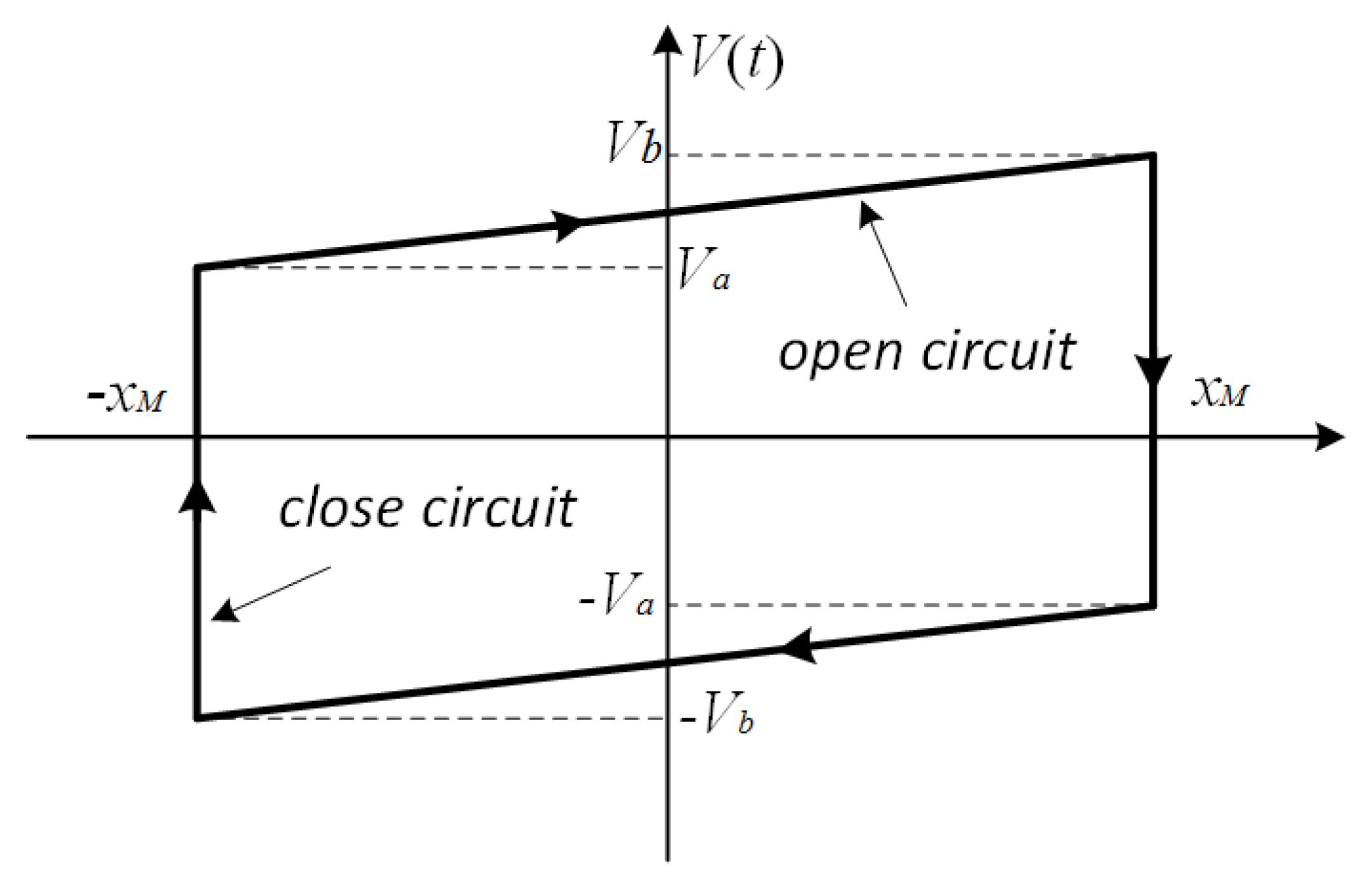
The relationship between the voltage of SSDI and the structural displacement is illustrated in Figure 2. Theoretically the voltages on piezo-patch before ( V b ) and after ( V a ) action of the switch are the same. Practically they have difference because of the resistance in circuit, namely:
V a = γ s V b
where γ s is the voltage inversion factor:
γ s = e π 2 Q s h u n t
and Q s h u n t is the electrical quality factor:
Q s h u n t = 1 R L C p
From the Figure 2, V b , V a and the structural displacement also have the following relation:
V b = V a + 2 α p C p x M
where α p is to the force factor, representing the force generated by unit voltage, and x M represents the displacement extreme of the host structure in each vibration cycle. Generally, α p is determined by experiment but can also be calculated if the material parameter of the piezoelectric patch is known [31].
With Equations (2) and (3), and Figure 2, the voltage on piezo-patch V shunt ( x , x ˙ , t ) can be derived [27]:
V shunt ( x , x ˙ , t ) = ( 1 + γ ) α p ( 1 γ ) C p x M sign [ x ˙ ( t ) ] + α p C p x ( t )
where x ( t ) is the displacement of the host structure the force generated by the piezo-voltage in SSDI shunt is proportional to the voltage based on the constitutive equations of piezoelectric material:
f shunt ( x , x ˙ , t ) = α p V shunt ( x , x ˙ , t ) = ( 1 + γ ) α p 2 ( 1 γ ) C p x M sign ( x ˙ ( t ) ) α p 2 C p x ( t )
It is clear that in Equation (6) the factor ( 1 + γ ) / ( 1 γ ) > 1 , therefor the absolute value of the first term is always greater than that of second term, which means that the direction of the force f s h u n t generated by the piezo-voltage in local SSDI shunt is always opposite to that of velocity x ˙ ( t ) . As a result, the force f s h u n t plays a role of damping, just like that induced by dry friction.

2.2. Dual-Connected SSDI

The proposed dual-connected configuration is illustrated in Figure 1b,c. In this configuration, the control rules of the switching circuit are different from the local SSDI described in Figure 1a. The extreme of the difference between two displacement-signals of two piezo-patches should be detected, other than one displacement-signal from one piezo-patch. When the relative displacement reaches the maximum or the minimum, the switch is closed and then it is open instantaneously. There are two ways of interconnection due to different alignment of the polling direction, termed the PP (positive-to-positive, Figure 1b) and PN (positive-to-negative, Figure 1c) connections respectively. In the PP connection, the positive poles of both PZT (Lead-Zirconate-Titanate) patches are connected together by the inductor and the switching. In the PN connection, the polling direction of structure 2 is reversed, so the positive pole of pzt1 and negative pole of pzt2 are connected in the SSDI circuit. In both the PP and PN connections, the switching is controlled by the same way, i.e., by the relative displacement of two structures.
In the dual-connected configuration, the intrinsic capacitance of the two piezo-patches are connected in series, and the equivalent capacitance in the electric field decreases by 50%. The electrical quality factor and the voltage inversion factor are deduced, according to Equations (1)–(3). The closed time of the switch becomes shorter. Thus, a larger quality factor and a higher voltage inversion factor are obtained in the dual-connected SSDI.
We first conduct some numerical analysis on a rather simplified model to show the characteristics of the dual-connected SSDI (with PP connection). The model is shown in Figure 3 where m 1 and m 2 represent the two modal mass, k 1 and k 2 represent the two modal stiffness, and c 1 , c 2 are the structural damping coefficients of the corresponding mechanical system, respectively. The mass m 1 and the mass m 2 are subjected to the external periodic excitation f 1 ( t ) and f 2 ( t ) respectively.
The governing equations of the system are:
{ m 1 x ¨ 1 + c 1 x ˙ 1 + ( k 1 + k e ) x 1 + f nl ( x 1 x 2 , x ˙ 1 x ˙ 2 , t ) = f 1 ( t ) m 2 x ¨ 2 + c 2 x ˙ 2 + ( k 2 + k e ) x 2 f nl ( x 1 x 2 , x ˙ 1 x ˙ 2 , t ) = f 2 ( t )
where k e represents the stiffness of the piezo-patch, and f nl is the nonlinear force generated by the dual-connected SSDI. The expression of f nl can be derived in the similar manner as f s h u n t in Section 2.1, and the only difference is to replace terms x and x ˙ in Equation (6) into x 1 x 2 and x ˙ 1 x ˙ 2 respectively:
f nl ( x 1 x 2 , x ˙ 1 x ˙ 2 , t ) = ( 1 + γ n e t ) α p 2 ( 1 γ n e t ) C p ( x 1 x 2 ) M sign ( x ˙ 1 x ˙ 2 ) α p 2 C p ( x 1 x 2 )
Note that the dual-connected SSDI generates a pair of self-equilibrium forces to the connected structures. The force applied to each structure is in opposite direction to the relative velocity thus plays the role of damping. In analogy with the dry friction dampers, a local SSDI is similar to an under-platform friction damper which can be modelled as a contact to the ground. In this case the damping force is only determined by the vibration of the local blade itself. However, a dual-connected SSDI is similar to a blade shroud, whose damping force is determined by the relative displacement. Besides the performance advantage of SSDI over dry friction [31], one additional advantage of the dual-connected SSDI is that one can choose which two blades to be connected, and this is more flexible than the shroud. A direct advantage of the dual-connected SSDI over the local SSDI is that at least half of the numbers of the semi-active circuits can be saved.
Here we consider harmonic excitation and compute the steady-state response in Equation (7). To solve this nonlinear structural dynamic problem, we employ the multi-harmonic balance method with a few numerical treatments to enhance the convergence. We have developed an in-house code which passes several test cases and has already been applied to analyze local SSDI [28], SSDNC [29] and dry friction dampers [37]. This method is much faster than the numerical integral method such as the Runge–Kutta method or the Newmark method to calculate the steady-state response. For the sake of brevity, we will not describe the method in this paper, and the readers can find detailed information in the aforementioned literature.
To illustrate the general trend of the results, we define some nondimensional parameters. They are: nondimensional time ω t ; nondimensional frequency ω k 1 m 1 ; nondimensional force f max ( f 1 ) ; nondimensional displacement x k 1 f 1 . These parameters will be used in Figure 4, Figure 5, Figure 6 and Figure 7.
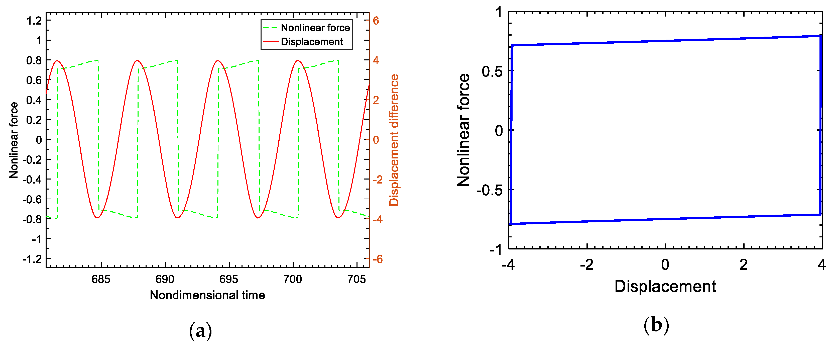
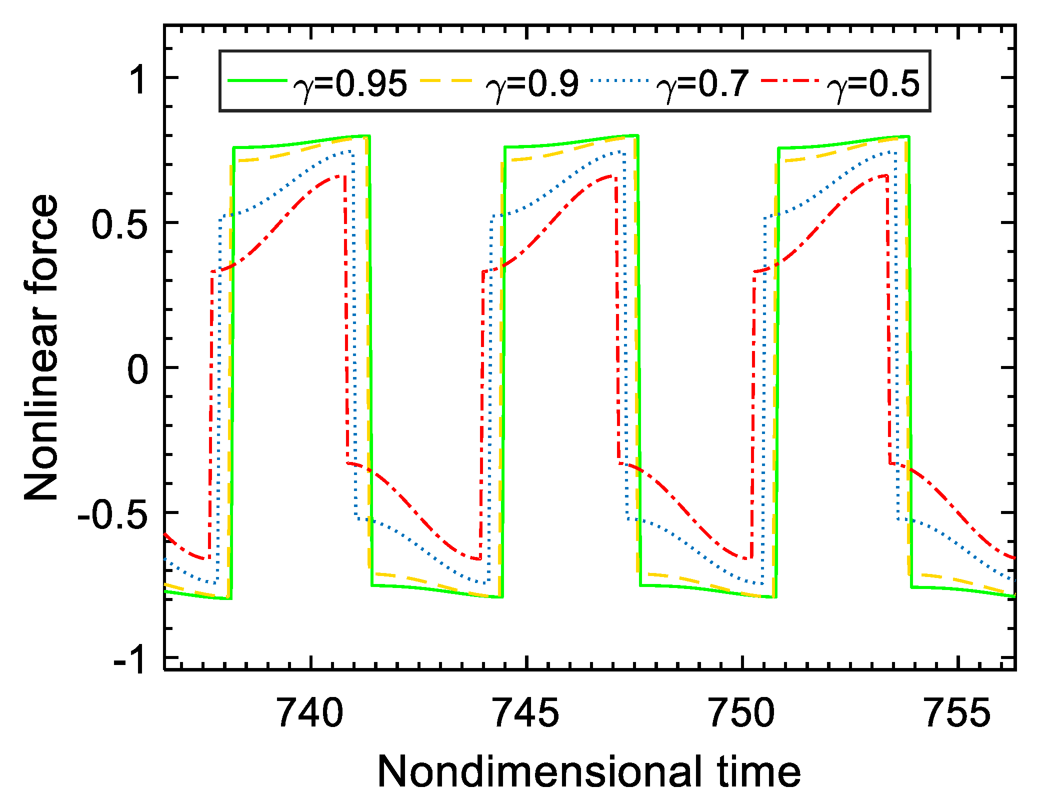
The steady-state response of the nonlinear force and the relative displacement are plotted in Figure 4b. It can be seen that every extremum of displacement response corresponds to a voltage-mutation (or inversion) from positive value to negative value or inversion. It is the voltage mutation that induces a force opposite to the relative velocity. The loop of the force with respect to the relative displacement is shown in Figure 4b. The area represents the energy dissipated in a vibrating period, and demonstrates the damping nature of the force. When the voltage inversion factor γ varies, the nonlinear force generated by the piezo-patch voltage will vary accordingly, which is illustrated in Figure 5. The higher the voltage inversion factor is, the closer the waveform of the nonlinear force is to the rectangle and the larger the damping effect is.
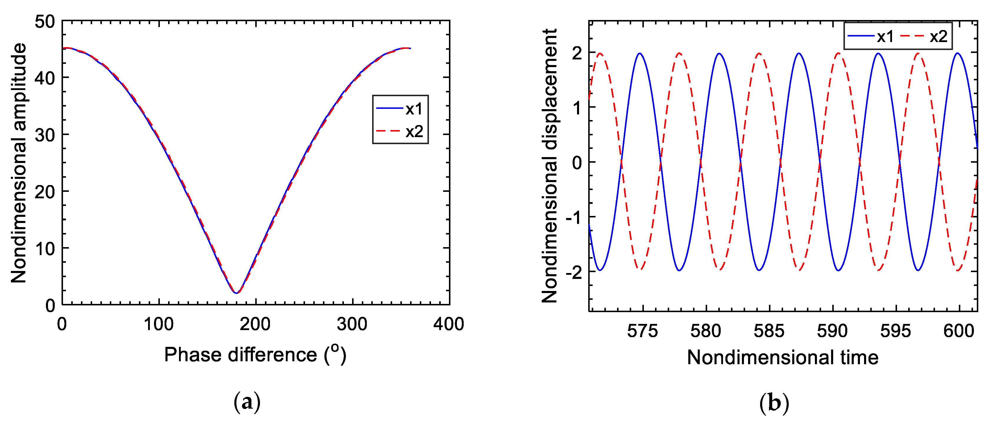
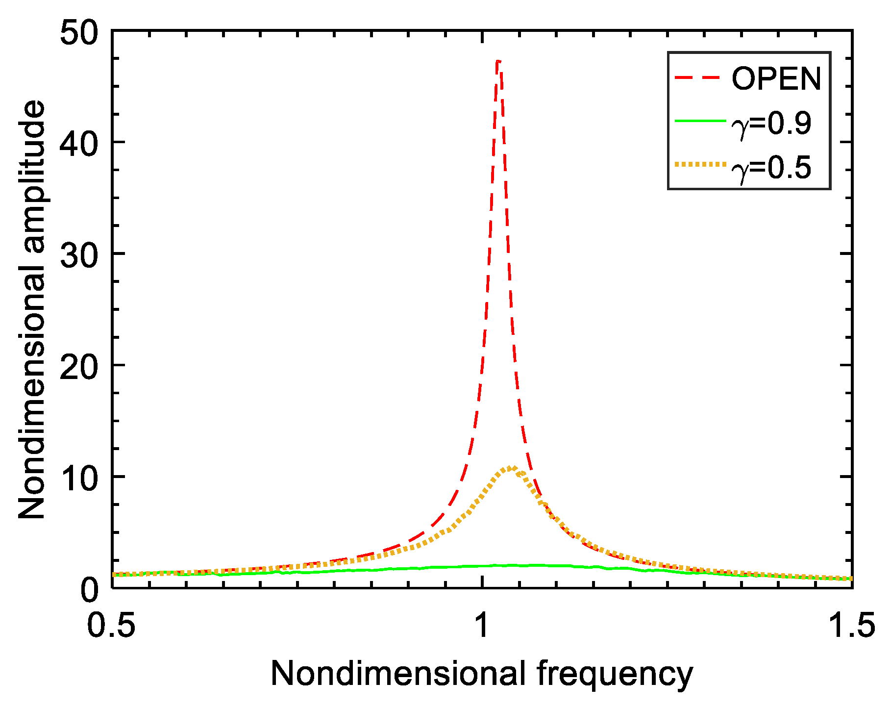
In the following, the damping effect of the shared SSDI shunt is studied through adjusting the phase-difference of two excitations (with the same amplitude). The evolution of response amplitudes of two masses under excitation with the phase difference are plotted in Figure 6a. When the phase difference of two excitations is 0 degrees, the two masses vibrate identically at any moment, and there is no voltage difference across the switch. The switch is out of action in this case and the vibration is not reduced at all. When the phase-difference of two excitations is 180 degrees, the two masses vibrate in opposite phase (as shown in Figure 6b), which means that the displacement-difference of the two masses keeps a great value at any moment, so the voltage difference across the switch reaches the maximum. As a result, the vibration amplitudes of the both two masses achieve the minimum, which means an optimum vibration damping effect. The results signify that the greater the displacement-difference of the masses, the better the damping effect of dual-connected SSDI. This conclusion makes special sense to study the suppression of local vibration of mistuned blisk. The vibration reduction can also be illustrated by comparing frequency-response curves with and without dual-connected SSDI, as shown in Figure 7. In addition, it’s worth noting that the larger the voltage inversion factor, the better the damping effect. When γ = 0.9 , the vibration reduction can be above 90%.

3. Design of Experiments

Experimental studies have been carried out to demonstrate the feasibility of the dual-connected SSDI. To do this, there are three sub-steps: (1) implement the SSDI circuit by a low-power manner; (2) test the damping performance of the local SSDI to validate the implementation and the results will be further compared with the dual-connected SSDI; and (3) test the damping performance of the dual-connected SSDI. In this section we present the details of these three aspects. To avoid the introduction of too many uncertainties and complexities, the experiments are conducted on beams. Namely, a single-beam test rig is designed for sub-step 2 and a double-beam test rig is designed for sub-step 3.

3.1. Implementation of the SSDI Circuit

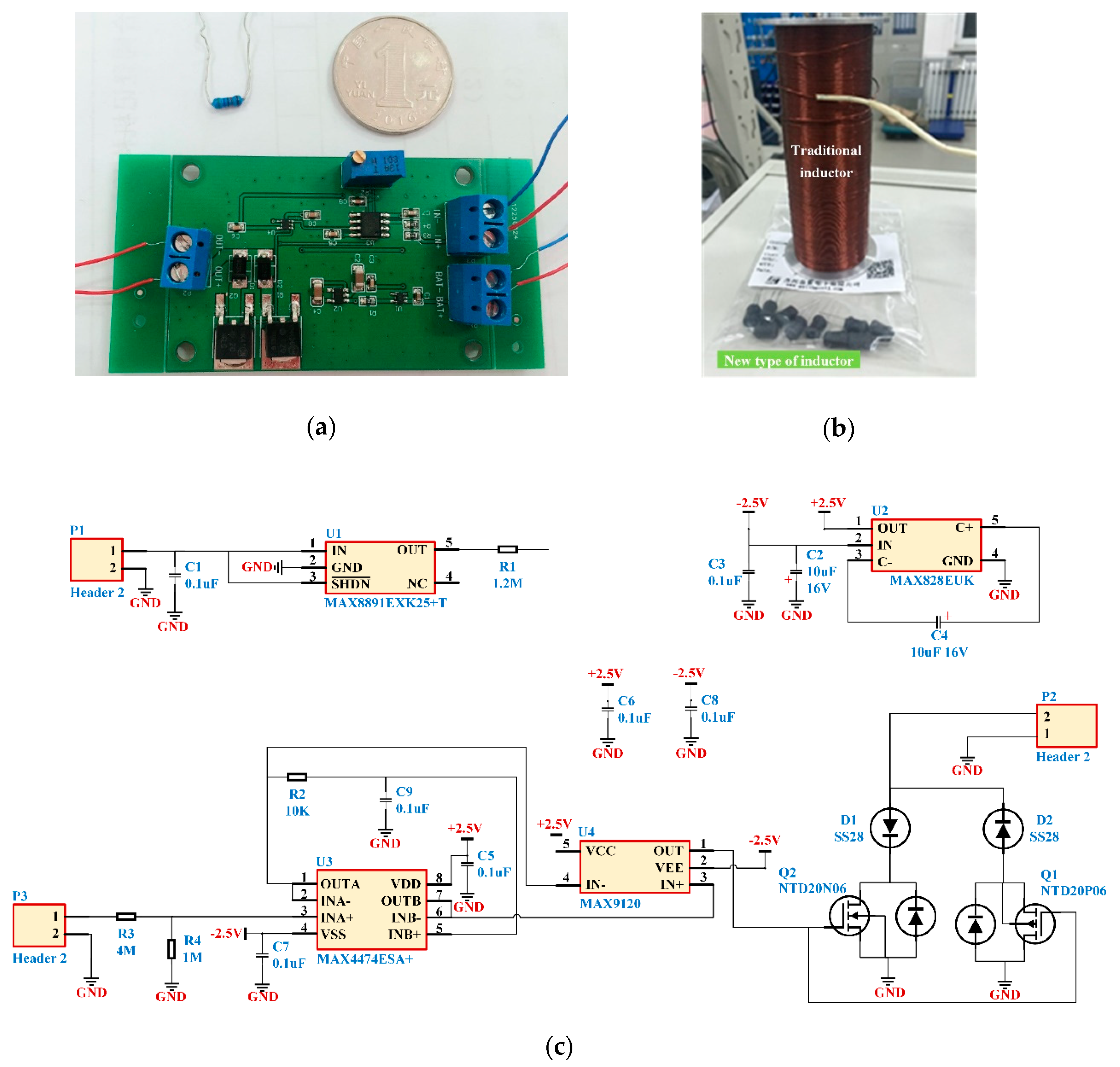
An integrated switching circuit is designed and implemented to fulfill the switch control. The size of the integrated circuit board is only 60 mm × 40 mm, as shown in Figure 8a. Three modules are included in the switching circuit: (1) a battery module; (2) a detection module of the displacement-extremum and (3) a switching control module. A low-pass filter is used to denoise the displacement signal and provide a proper phase delay. A comparator is implemented to finish the detection of displacement extremum by use of an ultra-low power operational amplifier setting in the circuit and by change of the displacement signal into a square signal for controlling the switch. The switch function is realized by an NMOS (N-channel metal oxide semiconductor FET) field-effect transistor and a PMOS (P-channel metal oxide semiconductor) field effect transistor (MOSFET, Metal-Oxide Semiconductor Field Effect Transistor) together with two diodes. The type of NMOS and PMOS in switching control block is NTD20N06 and NTD20P06, respectively. The comparator plays an important role in the switching circuit together with the MOSFETs, in addition it requires just a few μWs for switching operation. This low-power analog circuit can be powered by a 3V button battery (CR2032), and its battery capacity is 3 V × 210 mAh = 630 mWh. The switching circuit board needs about 0.5 mW power in total, which means that with a 3 V button battery the whole system can work for 630/0.5 = 1200 h. A 100 mH inductor is subsequently connected to the switching circuit. Thanks to technique progress, the volume of inductor is largely reduced and small like a resistor (Figure 8b). The schematic of the electric broad is shown in Figure 8c.

3.2. Single-Beam Test Rig with Local SSDI

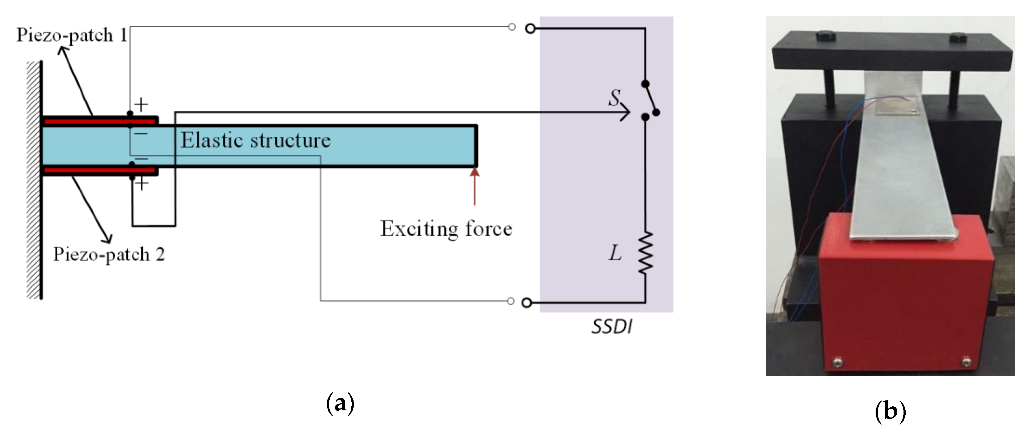
The configuration of the beam used in this experiment is shown in Figure 9 and the parameters are listed in Table 1. The beam is clamped at one end and a piezoelectric patch (referred to as PZT1) is bonded on the beam near the clamped end to connect with the SSDI shunt. Another piezoelectric patch (referred to as PZT2) is collocated on the other side as the sensor to detect displacement for the switching circuit. The poling directions of the two piezo-patches are perpendicular to the beam. An electromagnetic vibrator is set at free end of the beam to excite the beam vibration.
When a displacement extremum is detected in the voltage signal of PZT2, a trigger signal is generated to turn on the electronic switch so that the voltage on the PZT1 is inverted. Vibration tests of the beam with open circuit are also carried out under the same excitation to compare the dynamical characteristics of the system with SSDI shunt. The material parameters of piezoelectric patches are given in Table 2.
Owing to the smaller internal resistance (around 100 Ω) of the new type of inductor and large inductance, the electrical quality factor of the circuit implemented is higher than 10, which produces a large voltage inversion factor (around 0.9). Other facilities used in the experiment are: a signal generator, a power amplifier, a signal acquisition and processing system, and an oscilloscope (Figure 10c).

3.3. Double-Beam Test Rig with Dual-Connected SSDI

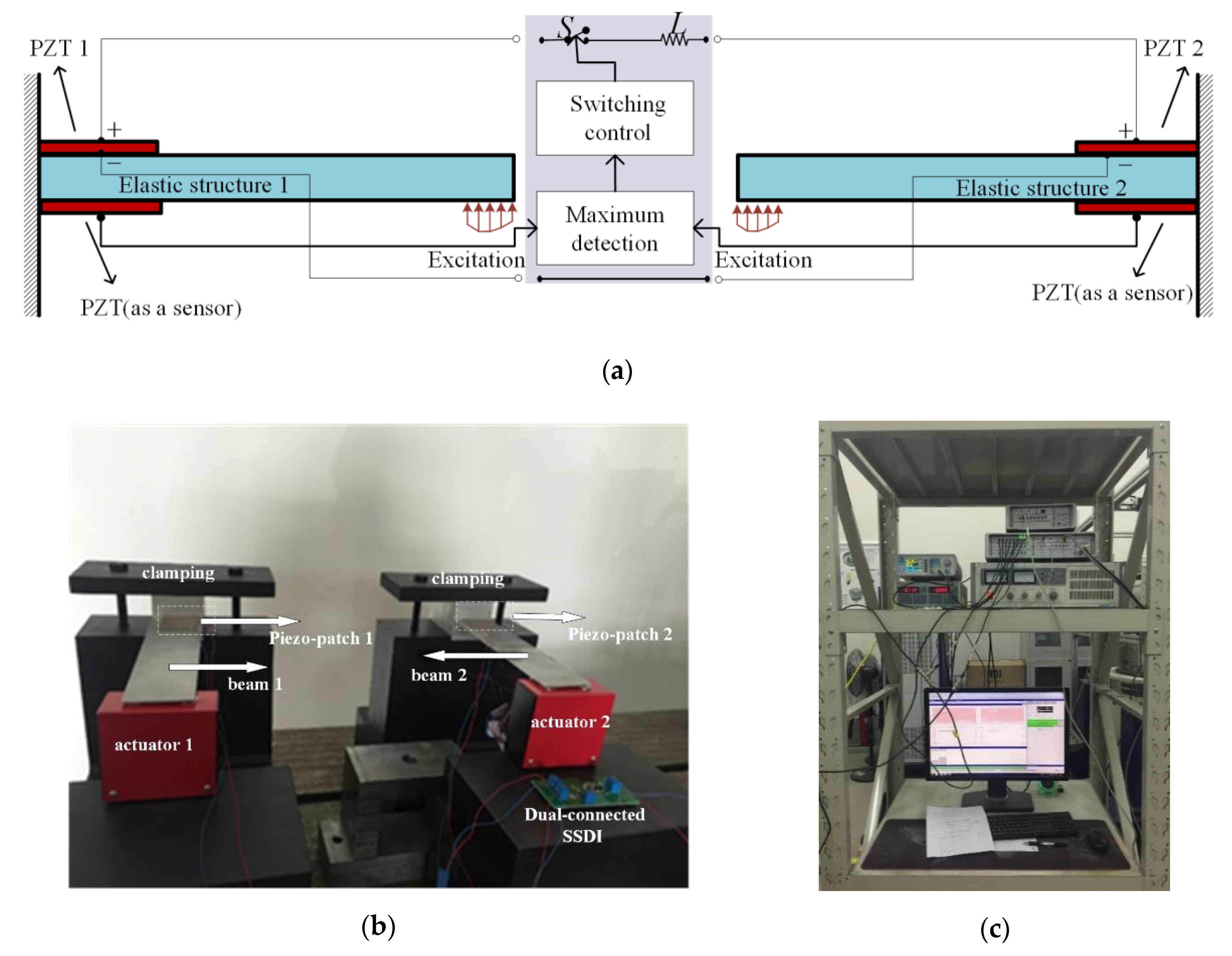
In order to experimentally exam the damping effect of the dual-connected SSDI, here we design a simple double-beam. It is composed of two cantilevered beams having the same geometric parameters and being interconnected by a SSDI circuit, as shown in Figure 10a. The two beams are excited respectively, at their free ends, by harmonic forces to simulate the difference of vibrations between blades of blisk. A group of piezoelectric patches are collocated near the clamped end of each beam. The piezoelectric patches on the top surface are connected with the SSDI circuit, while the two patches on the bottom surface are used as sensors to detect displacement signals to drive the switch in ‘closed’ or ‘open’ state. The extreme of the difference between two displacement-signals of two piezo-patches on the bottom surface of the two beams should be detected, other than one displacement-signal from one piezo-patch. When the difference reaches the maximum or the minimum, the switch is closed and then it is open instantaneously. The double-beam test rig are shown in Figure 10b. The two beams are excited by electromagnetic vibrators with the same amplitudes at the free end of the two beams, but the phase between the two excitations can be different.

4. Experimental Results and Discussions

4.1. Single-Beam with Local SSDI

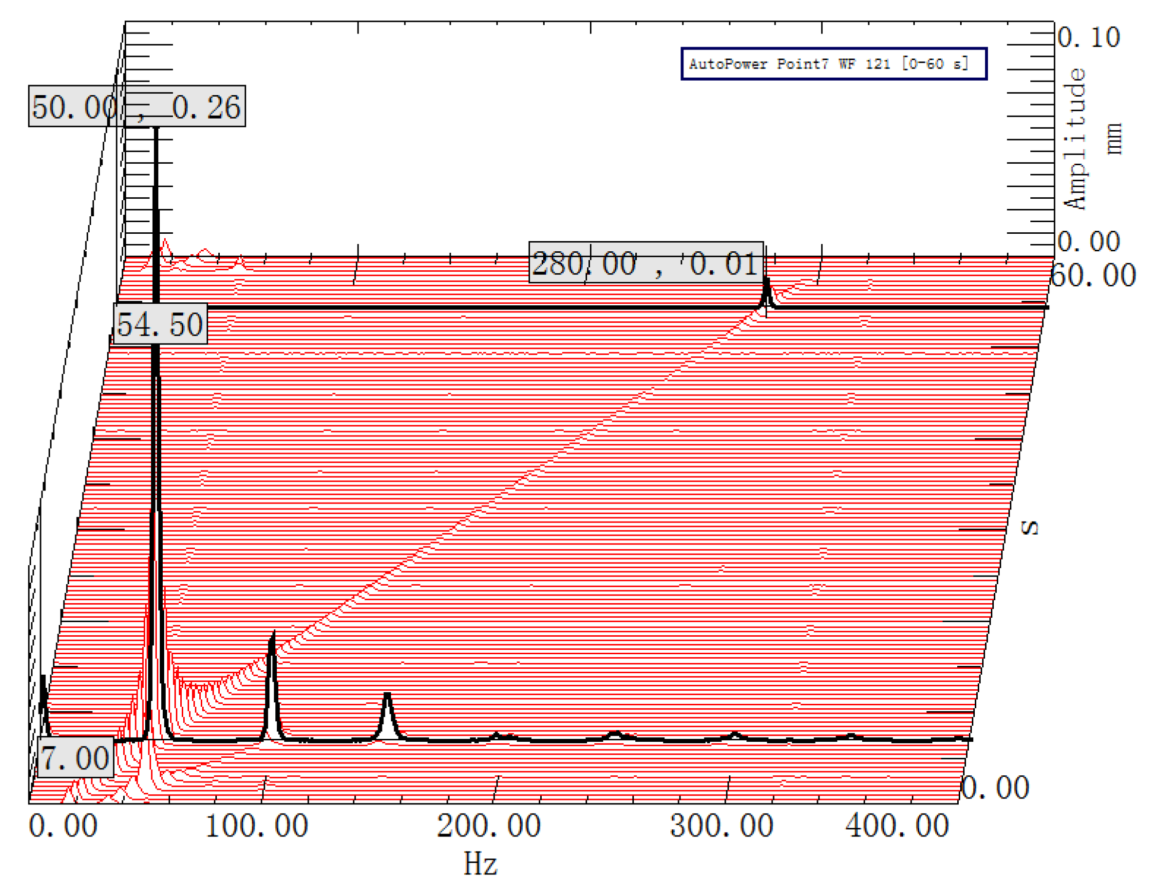
First, we measure the natural frequencies of the system. A response test is conducted while the piezoelectric patches are open-circuit. The excitation frequency varies from 0 Hz to 400 Hz and the amplitude remains the same. The waterfall plot of the response is given in Figure 11, where we can identify that the first two resonant frequencies of the beam without SSDI circuit are 50 Hz and 280 Hz, respectively. Note that Figure 11 shows the results of the short-time Fourier transform of the response signal, so we have time (s) in the z-axis. The first resonance is coincidently around 50 Hz (the alternating frequency), and this is validated by FEM (finite element method) computing when we tested the SSDI shunt [38]. The components of the higher harmonics (100 Hz and 150 Hz) may come from the error from the signal generator or some nonlinear aspects such as friction.
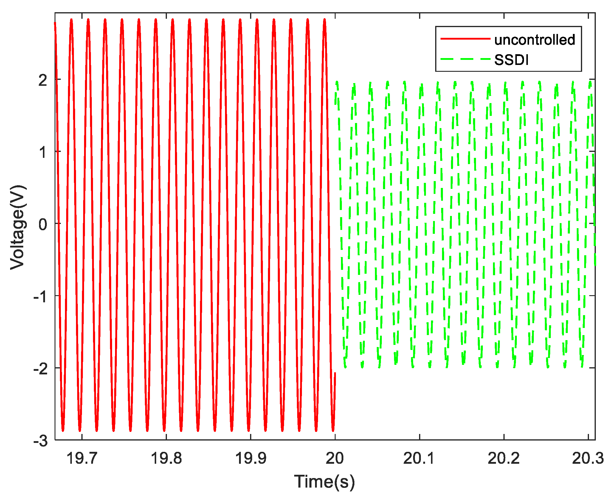
Then we test the steady-state response of the system by fixing the excitation frequency at a constant value for a relatively long time to cancel the free vibration. Figure 12a illustrates the evolution of the voltage on the PZT1 with and without SSDI circuit when the excitation frequency is set to 50 Hz (near the first-order resonance): the solid line corresponds to the open circuit, and the dotted line to the SSDI shunt. It can be seen that the controlled voltage has the similar square-wave like form to that given by theory (see Figure 4 and Figure 5).
The evolution of the voltage on the PZT2 is plotted in Figure 12b. Note that this voltage is proportional to the displacement at the point where the piezoelectric materials are bonded. As a comparison, the controlled voltage signal on PZT1 is plotted again in this figure. We can see that the voltage of PZT1 is reversed once the voltage of PZT2 arrives an extreme. The displacement responses (voltage on PZT2) of the beam with and without SSDI circuit are measured under excitation of 50 Hz, and are compared in Figure 13. The displacement amplitude of the system with SSDI shunt is reduced significantly (about 30%) compared with that of the uncontrolled case.
All these experimental results proved that the integrated switching circuit designed for SSDI effectively realizes the function we expect, that is, the voltage converts at the moment where the displacement arrives extreme. Furthermore, we can also see that the switch is still working when the displacement amplitude of the host structure is very small.

4.2. Double-Beam with Dual-Connected SSDI

As pointed out by the previous calculation (Figure 6), the effect of the dual-connected SSDI varies with the amplitude of the relative displacements between two components. To verify these results, the phase of exciting force to Beam 1 is fixed to 0 and the phase of Beam 2 is adjustable from 0 to 360 degree. Three circuit connection modes are considered in the test: open circuit, PP mode and PN mode.
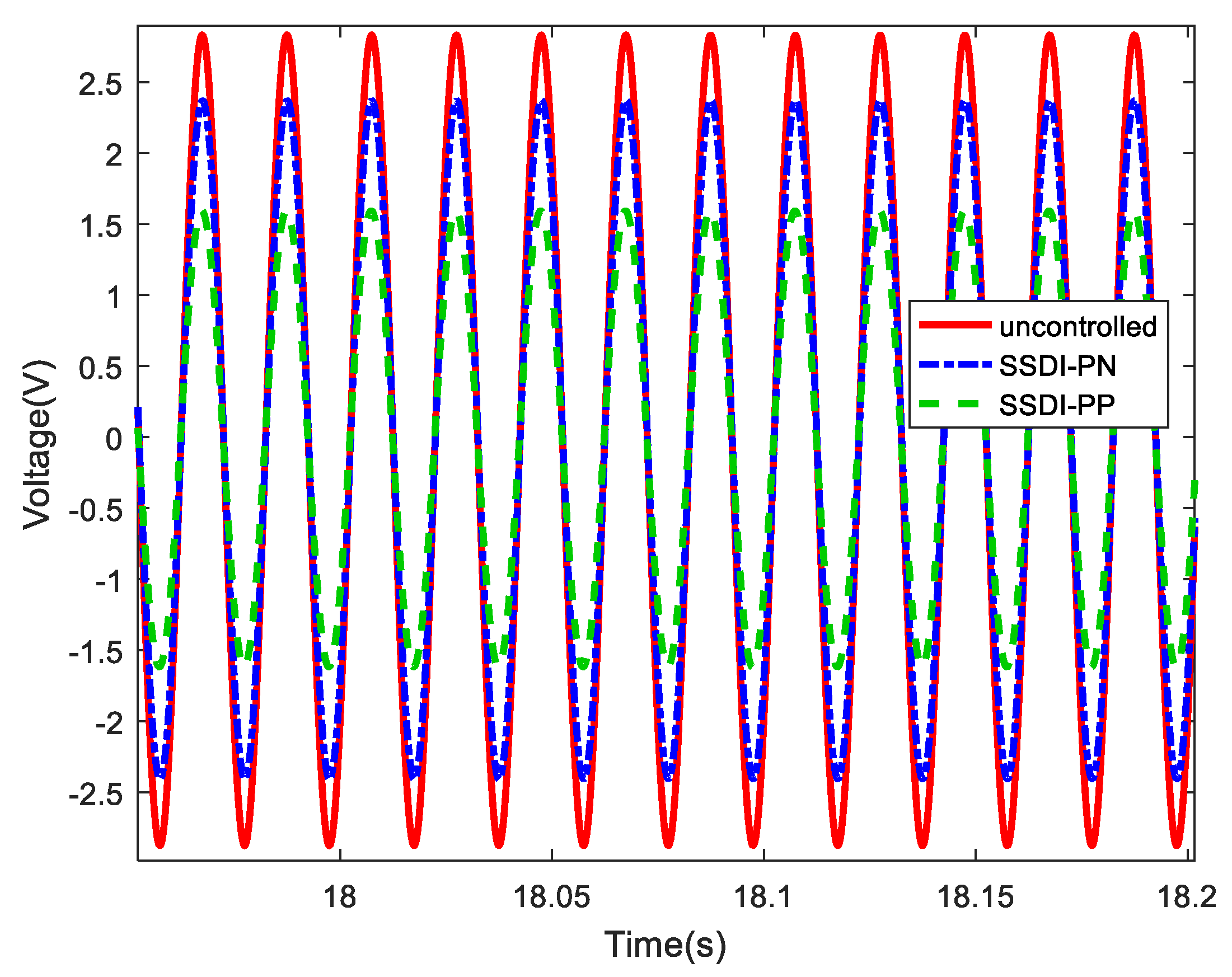
The displacement response of Beam 1 in three cases are measured when phase difference is 180 degree. Results are compared in Figure 14, where one can find that PN mode has the best damping effect. Setting the amplitude of open circuit mode as 100%, the vibration reduction of PP mode is about 16% and that of PN mode is about 44%.
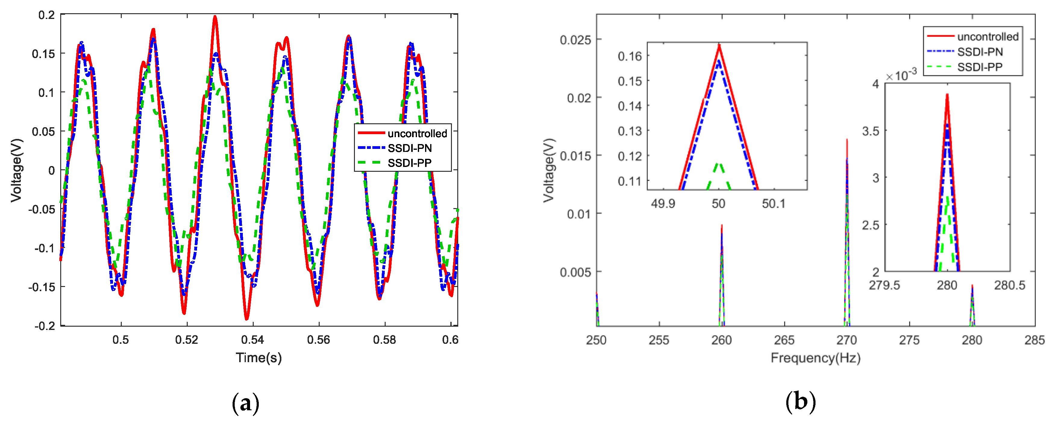
We also excite the two beams by white noise, and measure the displacement response curves of Beam 1 in three cases are, as presented in Figure 15a. The corresponding frequency response curves are shown in Figure 15b. The damping effect is summarized in Table 3 in terms of the reduction of displacement amplitude of Beam 1. It also proves that the vibration at first two resonant frequencies can be suppressed when shared SSDI shunt is applied especially in PP connection.
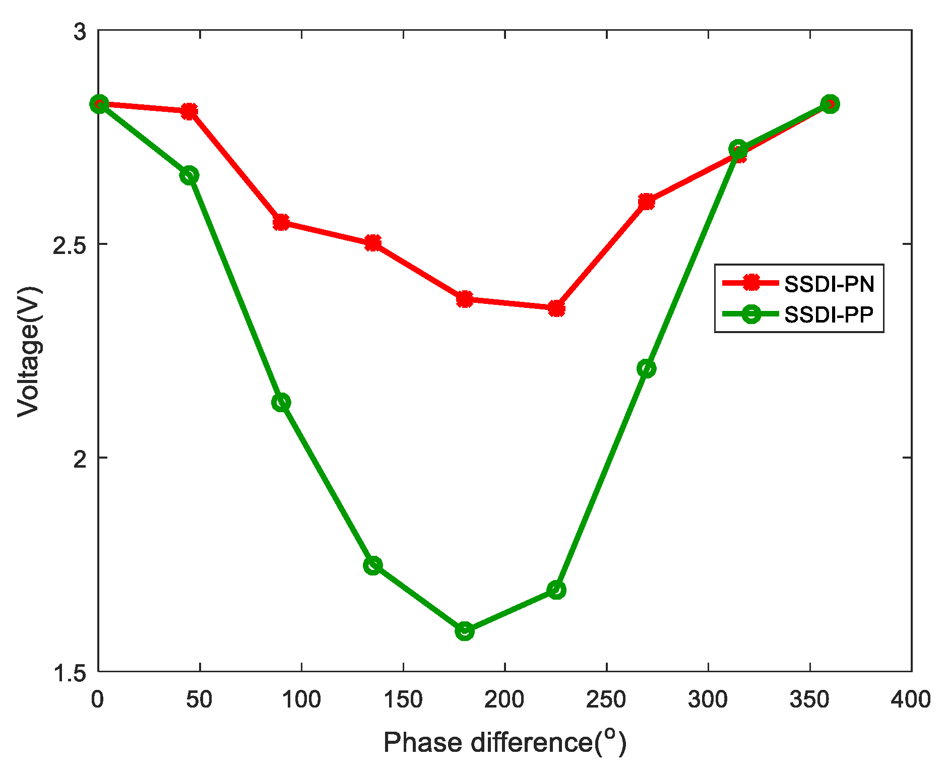
Eventually, we fix the amplitudes of excitation applied to two beams and let the exciting phase of Beam 2 vary from 0 to 360 degree with equal intervals (45 degree). The maximum of displacement amplitude of Beam 1 with PP and PN modes are shown in Figure 16. The curves verify that the displacement difference (realized by setting phase difference of the exciting signals of two beams) will affect the damping effect directly, and the greater the difference the better the damping effect. The vibration reduction of PP is larger than that of PN connection nearly at each case. It should be noted that the displacement amplitude of Beam 2 is suppressed simultaneously due to the performance of the shared SSDI shunt.
As mentioned, in both the PP and PN connections, the switching is controlled by the same way, i.e., by the relative displacement of two structures. In this regard, both PP and PN connections have poor performance for the in-phase vibration because the relative displacement is always zero and the switching cannot be triggered. The PP connection is expected to work best with out-of-phase vibration, and when the switching is closed, the voltage difference between PZT1 and PZT2 also reaches the maximum point. This generates the best damping. However, the PN connection still works poorly with out-of-phase vibration, because when the switching is closed (the maximum displacement difference occurs), the voltage difference between PZT1 and PZT2 is zero. These theoretical analyses are validated by results in Figure 16. In the experiments it is impossible to precisely control the amplitude and phase of two beams, and there will be some error. Therefore, in the out-of-phase case the voltage difference between PZT1 and PZT2 are not precisely zero. This can somehow generate some damping. That’s why we can still observe some damping from the PN connection. But the damping performance of PP is always better than PP and this matches with our understanding very well.

5. Vibration Reduction of Bladed Disks by Dual-Connected SSDI

The vibration amplitudes and phase of the blades in a bladed disk are not the same, due to mistuning and fluid excitation. Some of the blades can have the amplitude much greater than that of corresponding tuned blisk. In the light of the research presented in Section 3 to Section 5, the dual-connected SSDI is promising to mitigate such kind of vibration. If we appropriately chose the pairs of blades as two host structures to implement dual-connected SSDI, good damping performance may also be achieved. In this way, we can reduce 50% of the number of the semi-active switching circuit. In this section we conduct numerical simulations to explore the feasibility of applying the dual-connected SSDI to bladed blisks.

5.1. Dynamic Model

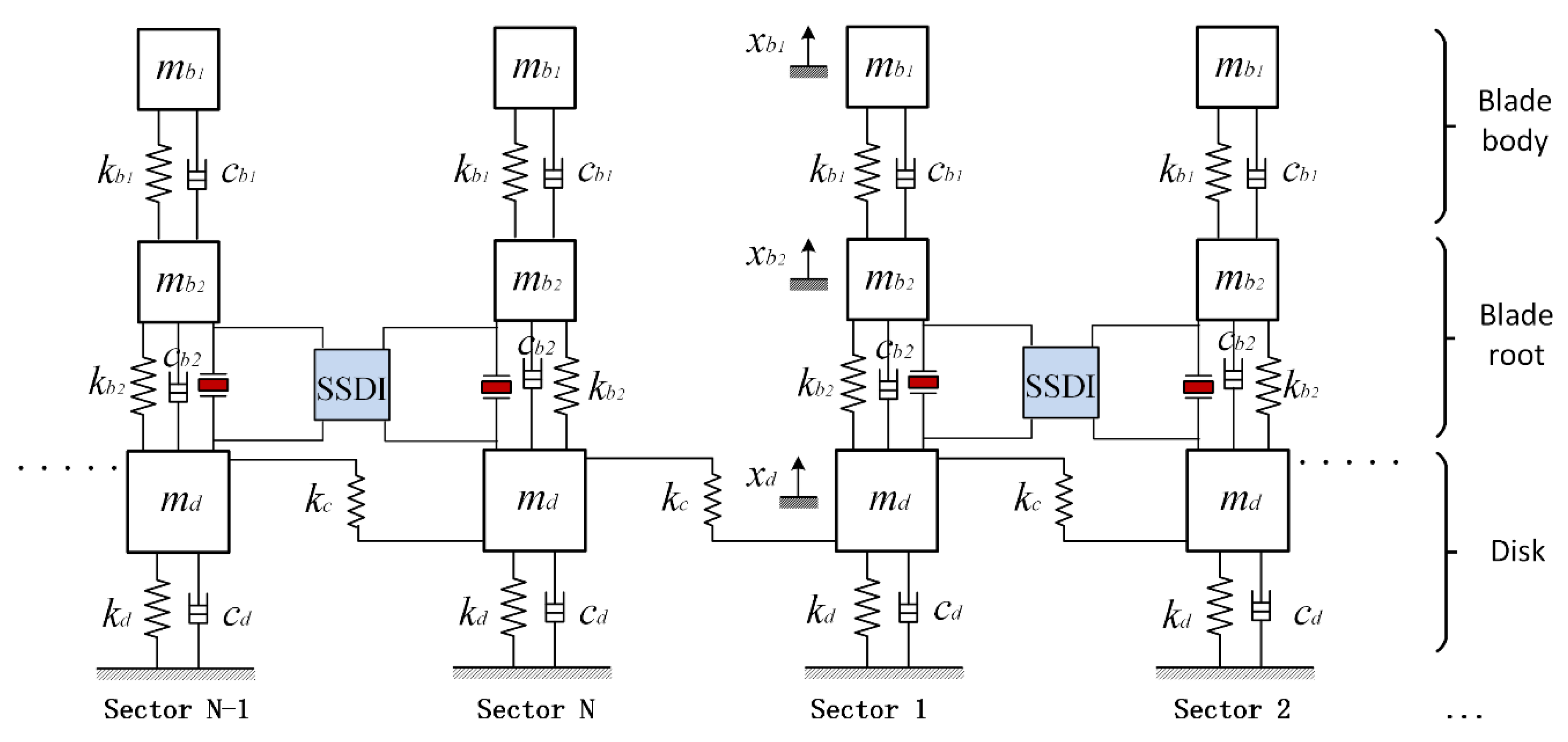
Here a lumped parameter model of bladed disk is considered, and it has three DOFs per sector as shown in Figure 17. Let N be the number of sectors of the model. m b 1 , m b 2 and m d represent the mass of blade body, blade root and the disk-sector, respectively. k b 1 , k b 2 and k d represent the stiffness of them. c b 1 , c b 2 and c d are the mechanical damping factors of them. k c is the coupling stiffness between adjacent disk sectors. A piezo-patch is supposed to be inserted at the root of blade, the position is between m b 2 and m d in the lumped parameter model in each sector. The piezo-patch is simulated to be parallel to k b 2 in the lumped parameter model. m e and k e are the mass and the stiffness of each piezo-patch.
Applying the piezoelectric SSDI shunt technique in blisk means that every piezo-patch will be connected with a SSDI shunt. But with the shared SSDI shunt, every two blades are connected in series with one SSDI circuit as shown in Figure 17. Thus, at least half of the needed switches can be saved.
The governing equations of the bladed disk can be expressed on a single sector (the Jth) based on Kirchhoff’s law:
{ m b 1 x ¨ b 1 , j + k b 1 x b 1 , j k b 1 x b 2 , j = f b 1 , j ( t ) ( m b 2 + m e ) x ¨ b 2 , j k b 1 x b 1 + ( k b 1 + k b 2 + k e ) x b 2 , j ( k b 2 + k e ) x d , j + f nl , j = f b 2 , j ( t ) m d x ¨ d , j ( k b 2 + k e ) x b 2 , j + ( k b 2 + k e + k d + 2 k c ) x d , j k c x d , j 1 k c x d , j + 1 = f d , j ( t )
where f nl , j is the nonlinear force produced by dual-connected SSDI and can be expressed as:
f nl , j = ( 1 + χ ) ( 1 χ ) α 2 x Δ , j M C p sign [ x ˙ b 2 , j + 1 x ˙ b 2 , j ] α 2 C p [ x b 2 , j + 1 x b 2 , j ] ,   j = 1 , 3 , 5 , N 1 ,
f nl , j = f nl , j 1 ,   j = 2 , 4 , 6 , N
and x b 1 , j and x b 2 , j are the displacements of the blade body and blade root in sector j respective; x d , j represents the displacement of disk sector j ; terms f b 1 , j , f b 2 , j and f d , j are the exciting forces from the airflow on the blade body, blade root and disk sector j , respectively.
To make the results more general, the parameters in Equation (9) are normalized by:
{ τ = ω t ω b 1 = k b 1 / m b 1 λ = ω / ω b 1 γ b = k b 2 / k b 1 γ d = k d / k b 1 γ c = k c / k b 1 γ e = k e / k b 1 γ p = α 2 / ( C p k b 1 ) δ mb = m b 2 / m b 1 δ md = m d / m b 1 , { f b 1 , j ( τ ) = f b 1 g j ( τ ) f b 2 , j ( τ ) = f b 2 g j ( τ ) f d , j ( τ ) = f d g j ( τ ) δ fb = f b 2 / f b 1 δ fd = f d / f b 1 x ¯ = f b 1 / k b 1 y b 1 , j = x b 1 , j / x ¯ y b 2 , j = x b 2 , j / x ¯ y d , j = x d , j / x ¯
Therefore, we obtain the following non-dimensional dynamic equations:
{ λ 2 y b 1 , j + y b 1 , j y b 2 , j = g j ( τ ) λ 2 ( δ mb + δ me ) y b 2 , j y b 1 , j + ( 1 + γ b + γ e ) y b 2 , j ( γ b + γ e ) y d , j + g nl , j = δ fb g j ( τ ) λ 2 δ md y d , j ( γ b + γ e ) y b 2 , j + ( γ b + γ e + γ d + 2 γ c ) y d , j γ c y d , j 1 γ c y d , j + 1 = δ fd g j ( τ )
where the non-dimensional nonlinear force of shared SSDI shunt is expressed as follows:
g nl , j = ( 1 + χ ) ( 1 χ ) γ p y Δ , j M sign ( y b 2 , j + 1 y b 2 , j ) γ p ( y b 2 , j + 1 y b 2 , j ) ,   j = 1 , 3 , 5 , N 1
g nl , j = g nl , j 1 j = 2 , 4 , 6 , N
where y Δ , j M represents the amplitude maximum of the relative displacement ( y b 2 , j + 1 y b 2 , j ) .
It is better to express the governing equations in the matrix form:
λ 2 M y ( τ ) + λ C y ( τ ) + K y ( τ ) + g nl ( y ( τ ) , y ( τ ) , τ ) = g ( τ )
where vector of generalized displacement y = [ y 1 , y 2 , , y N ] T and y j = [ y b 1 , j , y b 2 , j , y d , j ] T . The mass matrix writes:
M = Bdiag ( M 1 , M 2 , M 3 , , M N )
where Bdiag() represents a block diagonal matrix, and the sub-matrix has the form:
M j = ( 1 0 0 0 δ mb + δ me 0 0 0 δ md )
The stiffness matrix writes:
K = Bcirc ( K 1 , K c , 0 , , 0 , K c )
where and Bcirc() represents a block circulant matrix, and the sub-matrix has the form:
K j = ( 1 1 0 1 1 + γ b + γ e ( γ b + γ e ) 0 ( γ b + γ e ) γ b + γ e + γ d + 2 γ c )
K c = ( 0 0 0 0 0 0 0 0 γ c )
In this work, the Rayleigh damping model are used to describe the mechanical damping of the blisk:
C = α c M + β c K
where α c and β c are the coefficients of Rayleigh damping.
Random mistuning is supposed to occur in the stiffness of the blade. Hence, the non-dimensional equations of the writes:
M y ( τ ) + C y ( τ ) + ( K + Δ K ) y ( τ ) + g nl ( y ( τ ) , y ( τ ) , τ ) = g ( τ )
where he mistuning matrix Δ K of blade stiffness is given as follows:
Δ K = Bdiag ( Δ K 1 , Δ K 2 , , Δ K N )
and
Δ K j = [ 1 + δ γ b , j ( 1 + δ γ b , j ) 0 ( 1 + δ γ b , j ) 1 + γ b + 2 δ γ b , j + γ e ( γ b + δ γ b , j + γ e ) 0 ( γ b + δ γ b , j + γ e ) γ b + δ γ b , j + γ e + γ d + 2 γ c ]
The bladed disks are subjected to the traveling wave excitation produced by up-stream vanes and the rotor rotation. If the traveling wave has only one harmonic, the excitation has the following expression:
g j ( τ ) = [ g b 1 , 1 ( τ ) , g b 2 , 1 ( τ ) , g d , 1 ( τ ) ] T e i ( j 1 ) E θ
where [ g b 1 , 1 ( τ ) , g b 2 , 1 ( τ ) , g d , 1 ( τ ) ] T is the excitation vector applied to the reference sector. The symbol defines as the Kronecker tensor product, i is the imaginary unit and θ = 2 π / N is the phase difference between the adjacent blades. It is implied that the exciting force has the same magnitude but different phase in each sector. This kind of excitation in aero-engines is normally called the engine-order excitation and parameter E is the excitation order. The excitation from the airflow usually includes multiple harmonics, we will consider this situation later. The main non-dimensional parameters are listed in Table 4.

5.2. Forced Response Results

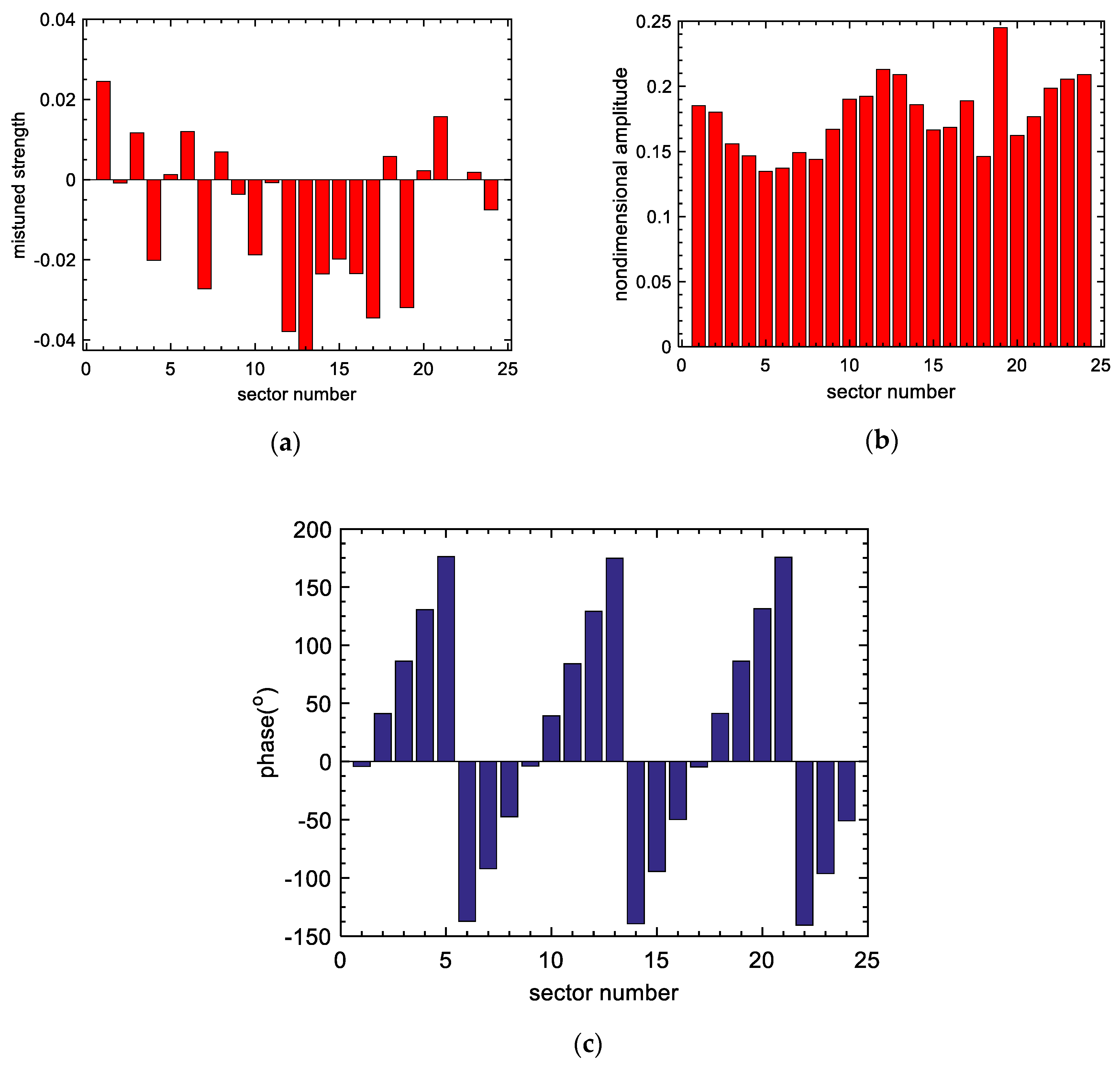
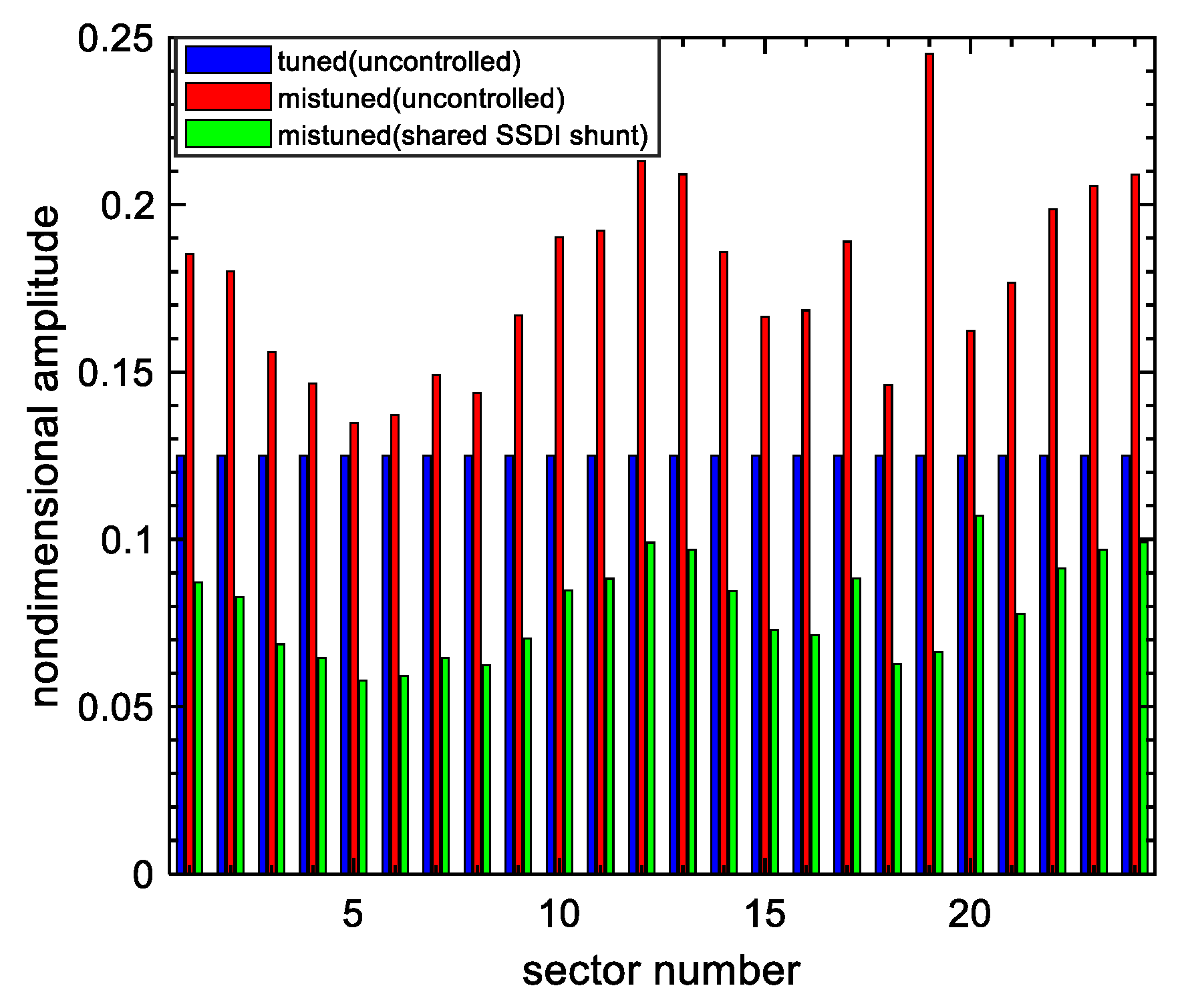
A random mistuning pattern of the blade stiffness is shown in Figure 18a. Its mean value is 0 and standard deviation is 2%. First, we do not apply any piezoelectric damping, and the response amplitudes of 24 blades are shown in Figure 18b. It can be seen that some blades (for example, Blade 19) have larger response amplitude than others. Figure 18c shows the phase response associated with Figure 18b. Since the excitation has engine-order three, we can anticipate an approximate 45 degree (360 × 3/24) phase difference of the consecutive blades. This can be verified in Figure 18c. The response amplitudes of 24 blades in three cases (tuned, mistuned with and without dual-connected SSDI) are compared in Figure 19. To solve the nonlinear equations, multi-harmonic balance method is employed with a few additional techniques to improve the convergence [28,31].
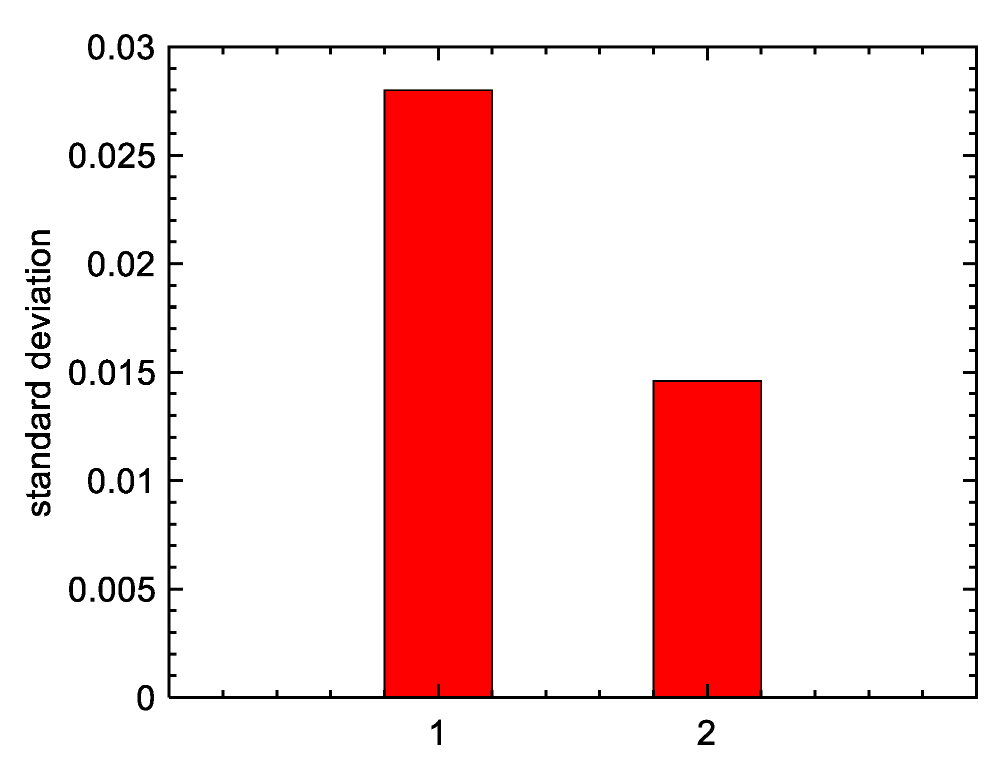
The vibration of blades is significantly reduced by the dual-connected SSDI (around 50% reduction). The blade originally with largest amplitude receives the largest amount of vibration reduction and becomes one of the blade with smallest vibration in the controlled case. On other hand, the vibration localization is also mitigated, as can be seen by the standard deviation of blade amplitudes shown in Figure 20. According to Figure 18c, the interconnected blades has vibration phase around 45 degrees, and according to Figure 16, it is not the best situation but can still generate some damping. We would like to note that the results in Figure 16 are obtained where the two structures do not have any mechanical coupling. However, in Figure 19 there are mechanical coupling among the interconnected blades (by the disk). Moreover, in the real working situation of bladed disks, the phase difference can be different when the load and rotation speed changes. Therefore, it is difficult to tune the interconnection always to the best situation. The results in Figure 19 show that even though the phase difference may not be the best case, substantial damping can still be generated.
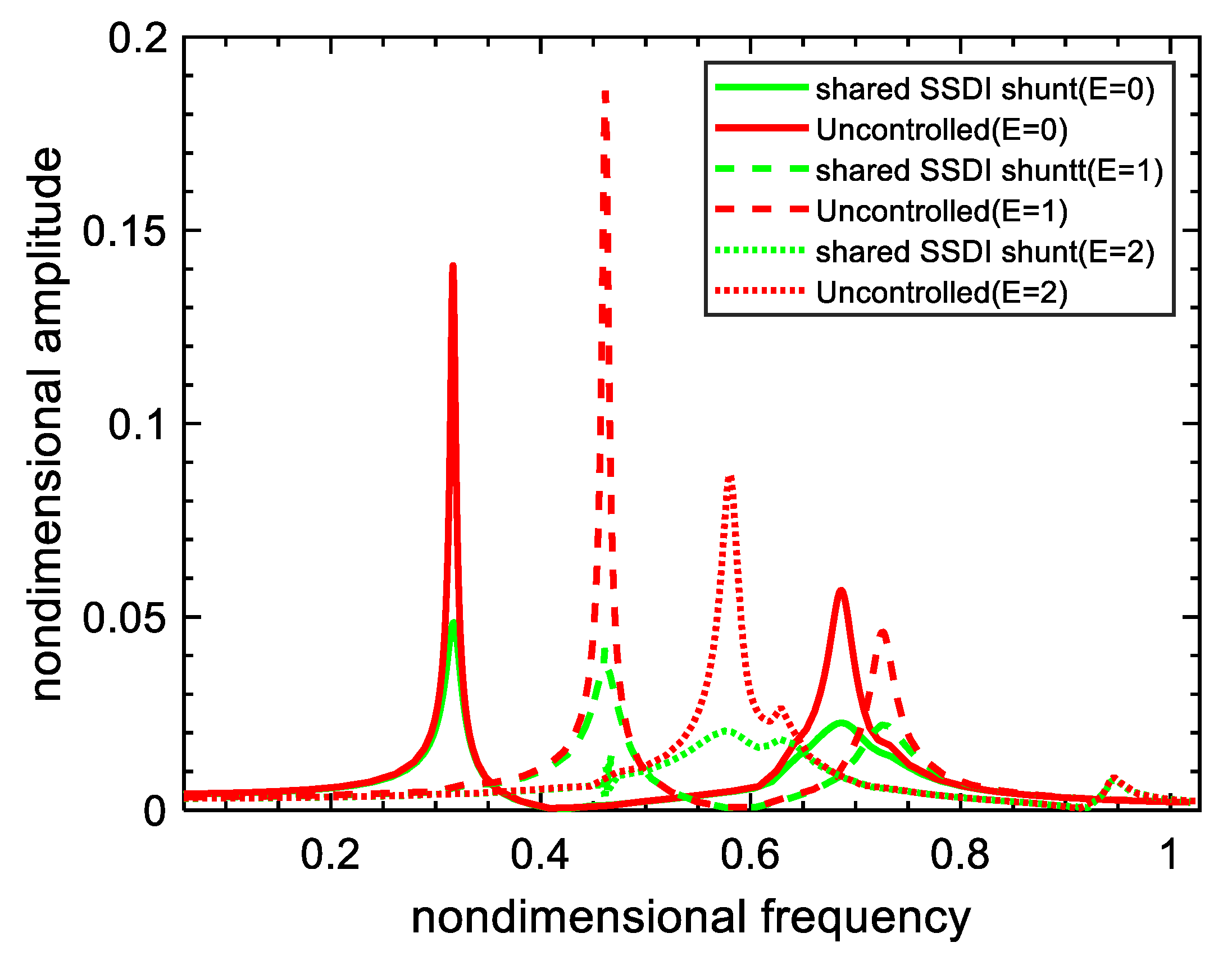
We select the frequency-response curves among 24 blades with largest peak value under different engine-order excitations (E = 0, 1, 2 respectively) and plot them in Figure 21. Different vibration modes are excited by different engine order excitation. This means that not only the amplitudes but also the phases of the blades are different. The damping effect of the dual-connected SSDI is significant, despite a slightly vary with the different modes.
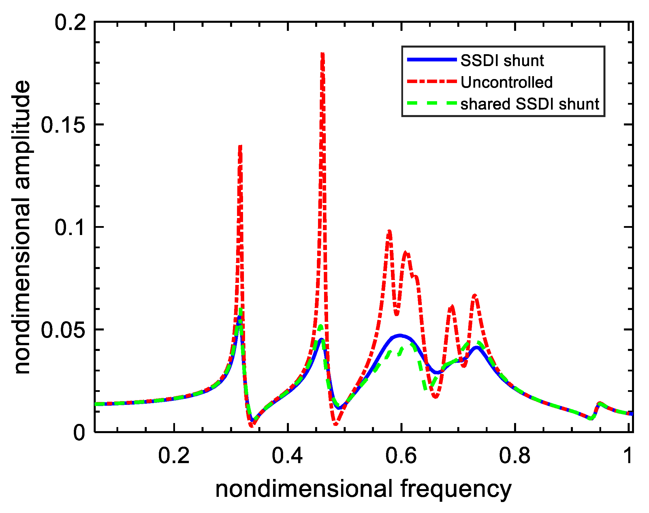
Figure 22 shows the greatest frequency-response in 24 blades with dual-connected SSDI under multi-harmonic excitation (including engine-orders 0, 1 and 2 at the same time). Results of local SSDI are also plotted for the sake of comparison. Note that all vibration peaks excited by multi-harmonic excitation can be suppressed by the dual-connected SSDI shunt, the effect is comparable with that of the local SDI shunt. However, the number of semi-active circuits in the dual-connected SSDI shunt is only half those of the local SSDI.

6. Conclusions

We have proposed the dual-connected SSDI to control the vibration of bladed disks in aero-engines. The dynamic model of the new circuit configuration is derived, and the damping performance is numerically demonstrated. The dual-connected SSDI is implemented by a low-power circuit board and the performance is experimentally validated by a double-beam test rig. The main finds are:
  • The dual-connected configuration can increase the voltage inversion factor compared with the local configuration. The dual-connected SSDI generates a pair of self-equilibrium forces to the connected structures. The force applied to each structure is in opposite direction to the relative velocity thus plays the role of damping. The damping performance increases monotonously with the amplitude of the relative displacement. In this regard, the in-phase vibration cannot be damped by the proposed approach, and this can be a limitation in the general application. However, in the application of bladed disks, due to the complexity of the excitation and existing of many (20~30) blades, we can always avoid the worst working condition. This is one of the reasons why we think the dual-connected SSDI can be a good candidate for vibration reduction of bladed disks. Additionally, the dual-connected SSDI share the limitations with traditional local SSDI, such as the need of external power and the difficulty of reliably implanting piezoelectric materials into the blades.
  • The dual-connected configuration can reduce at least half the number of switching shunts while maintain nearly the same performance as the conventional (local) SSDI, while applying to bladed disks. It not only reduces the vibration amplitude, but also mitigate the vibration localization. All the vibration peaks excited by multi-engine-order force can be effectively suppressed. Note that the proposed configuration does not extend the applicable frequency band of the SSDI technique. It basically shares the same frequency band of the local SSDI. As proved in the literature [24,25,26,27,28,29,30,31,32] that the SSDI can work in a relatively wide frequency band thus provides multi-modal damping. It is important to keep the voltage reverse happened in a very short time compared to the vibration period. To do this the inductance is chosen such that the oscillating frequency of the inductance with intrinsic capacitance is more than 20 times higher than the vibration frequency. The damping performance is also closely related to the modal electromechanical coupling factor (MEMCF) of the piezoelectric patch [39]. Once the geometric parameters of the piezoelectric patch are fixed, it can provide good MEMCF in a certain frequency band. For example, when elastic wave-length associated the vibration is too small or too long compared to the length of the patch, generally the MEMCF is very low [40]. One should be aware these general limitations of SSDI and piezo-based techniques during practical implementation.
  • Future work can focus on the optional connection in blades in order to further reduce the number of switching elements.

Author Contributions

Conceptualization, F.Z. and L.L.; methodology, F.Z. and J.L.; validation, F.Z. and J.L.; writing—original draft preparation, L.L. and F.Z.; writing—review and editing, Y.F.; visualization, F.Z. and Y.F.; supervision, L.L.; project administration, Y.F.; funding acquisition, L.L. and Y.F. All authors have read and agreed to the published version of the manuscript.

Funding

This research was funded by National Natural Science Foundation of China, grant numbers 51675022 and 11702011.

Conflicts of Interest

The authors declare no conflicts of interest. The funders had no role in the design of the study; in the collection, analyses, or interpretation of data; in the writing of the manuscript, or in the decision to publish the results.

References

  1. Petrov, E.P.; Ewins, D.J. Effects of damping and varying. contact area at blade-disk joints in forced response analysis of bladed disk assemblies. J. Turbomach. 2006, 128, 403–410. [Google Scholar] [CrossRef]
  2. Griffin, J.H. A Review of Friction Damping of Turbine Blade Vibration. Int. J. Turbo Jet Engines 1990, 7, 297–308. [Google Scholar] [CrossRef]
  3. Zhang, D.; Fu, J.; Zhang, Q.; Hong, J. An effective numerical method for calculating nonlinear dynamics of structures with dry friction: Application to predict the vibration response of blades with underplatform dampers. Nonlinear Dyn. 2017, 88, 223–237. [Google Scholar] [CrossRef]
  4. Laxalde, D.; Thouverez, F.; Lombard, J. Forced Response Analysis of Integrally Bladed Disks with Friction Ring Dampers. J. Vib. Acoust. 2010, 132, 011013. [Google Scholar] [CrossRef] [Green Version]
  5. Yan, B.; Wang, K.; Hu, Z.; Wu, C.; Zhang, X. Shunt Damping Vibration Control Technology: A Review. Appl. Sci. 2017, 7, 494. [Google Scholar] [CrossRef]
  6. Gripp, J.A.B.; Rade, D.A. Vibration and noise control using shunted piezoelectric transducers: A review. Mech. Syst. Signal Process. 2018, 112, 359–383. [Google Scholar] [CrossRef]
  7. Forward, R.L. Electronic damping of vibrations in optical structures. Appl. Opt. 1979, 18, 690–697. [Google Scholar] [CrossRef]
  8. Hagood, N.W.; von Flotow, A. Damping of structural vibrations with piezoelectric materials and passive electrical networks. J. Sound Vib. 1991, 146, 243–268. [Google Scholar] [CrossRef]
  9. Min, J.B.; Duffy, K.P.; Choi, B.B.; Provenza, A.J.; Kray, N. Numerical modeling methodology and experimental study for piezoelectric vibration damping control of rotating composite fan blades. Comput. Struct. 2013, 128, 230–242. [Google Scholar] [CrossRef]
  10. Bachmann, F.; de Oliveira, R.; Sigg, A.; Schnyder, V.; Delpero, T.; Jaehne, R.; Bergamini, A.; Michaud, V.; Ermanni, P. Passive damping of composite blades using embedded piezoelectric modules or shape memory alloy wires: A comparative study. Smart Mater. Struct. 2012, 21, 075027. [Google Scholar] [CrossRef]
  11. Deng, P.; Li, L.; Li, C. Study on vibration of mistuned bladed disk with bi-periodic piezoelectric network. Proc. Inst. Mech. Eng. Part G: J. Aerosp. Eng. 2017, 231, 350–363. [Google Scholar] [CrossRef]
  12. Liu, J.; Li, L.; Fan, Y.; Deng, P. Research on vibration suppression of a mistuned blisk by a piezoelectric network. Chin. J. Aeronaut. 2018, 31, 286–300. [Google Scholar] [CrossRef]
  13. Li, L.; Deng, P.; Fan, Y. Dynamic characteristics of a cyclic-periodic structure with a piezoelectric network. Chin. J. Aeronaut. 2015, 28, 1426–1437. [Google Scholar] [CrossRef] [Green Version]
  14. Yu, H.; Wang, K.W. Vibration Suppression of Mistuned Coupled-Blade-Disk Systems Using Piezoelectric Circuitry Network. J. Vib. Acoust. 2009, 131, 021008. [Google Scholar] [CrossRef]
  15. Yu, H.; Wang, K.W. Piezoelectric Networks for Vibration Suppression of Mistuned Bladed Disks. J. Vib. Acoust. 2007, 129, 559. [Google Scholar] [CrossRef]
  16. Mokrani, B.; Bastaits, R.; Horodinca, M.; Romanescu, I.; Burda, I.; Viguié, R.; Preumont, A. Parallel Piezoelectric Shunt Damping of Rotationally Periodic Structures. Adv. Mater. Sci. Eng. 2015, 2015, 1–12. [Google Scholar] [CrossRef] [Green Version]
  17. Park, C.H.; Inman, D.J. Enhanced Piezoelectric Shunt Design. Shock Vib. 2003, 10, 127–133. [Google Scholar] [CrossRef]
  18. Vatavu, M.; Nastasescu, V.; Turcu, F.; Burda, I. Voltage-controlled synthetic inductors for resonant piezoelectric shunt damping: A comparative analysis. Appl. Sci. 2019, 9, 4777. [Google Scholar] [CrossRef] [Green Version]
  19. Giorgio, I.; Culla, A.; del Vescovo, D. Multimode vibration control using several piezoelectric transducers shunted with a multiterminal network. Arch. Appl. Mech. 2009, 79, 859–879. [Google Scholar] [CrossRef] [Green Version]
  20. Behrens, S.; Moheimani, S.O.R. Current Flowing Multiple-Mode Piezoelectric Shunt Dampener. In Proceedings of the Smart Structures and Materials 2002: Damping and Isolation, San Diego, CA, USA, 17–21 March 2002; Agnes, G.S., Ed.; 2002; pp. 217–226. [Google Scholar] [CrossRef]
  21. Slater, J.C.; Minkiewicz, G.R.; Blair, A.J. Forced Response of Bladed Disk Assemblies—A Survey. Shock Vib. Dig. 1999, 31, 17–24. [Google Scholar] [CrossRef]
  22. Xie, W.; Wang, X. Vibration Mode Localization in One-Dimensional Systems. AIAA J. 1997, 35, 1645–1652. [Google Scholar] [CrossRef]
  23. Ewins, D.J. Vibration Modes of Mistuned Bladed Disks. J. Eng. Power. 1976, 98, 349–355. [Google Scholar] [CrossRef]
  24. Richard, C.; Guyomar, D.; Audigier, D.; Ching, G. Semi-Passive Damping Using Continuous Switching of a Piezoelectric Device. In Proceedings of the Smart Structures and Materials 1999: Passive Damping and Isolation, Newport Beach, CA, USA, 1 March 1999; Hyde, T.T., Ed.; 1999; pp. 104–111. [Google Scholar] [CrossRef]
  25. Richard, C.; Guyomar, D.; Audigier, D.; Bassaler, H. Enhanced Semi-Passive Damping Using Continuous Switching of a Piezoelectric Device on an Inductor. In Proceedings of the Smart Structures and Materials 2000: Damping and Isolation, Newport Beach, CA, USA, 6–9 March 2000; Hyde, T.T., Ed.; 2000; pp. 288–299. [Google Scholar] [CrossRef]
  26. Corr, L.R.; Clark, W.W. Comparison of low-frequency piezoelectric switching shunt techniques for structural damping. Smart Mater. Struct. 2002, 11, 370–376. [Google Scholar] [CrossRef]
  27. Ji, H.; Qiu, J.; Cheng, J.; Inman, D. Application of a Negative Capacitance Circuit in Synchronized Switch Damping Techniques for Vibration Suppression. J. Vib. Acoust. 2011, 133, 041015. [Google Scholar] [CrossRef]
  28. Liu, J.; Li, L.; Huang, X.; Jezequel, L. Dynamic characteristics of the blisk with synchronized switch damping based on negative capacitor. Mech. Syst. Signal Process. 2017, 95, 425–445. [Google Scholar] [CrossRef]
  29. Liu, J.; Li, L.; Fan, Y.; Huang, X. A Modified Nonlinear Modal Synthesis Scheme for Mistuned Blisks with Synchronized Switch Damping. Int. J. Aerosp. Eng. 2018, 2018, 1–15. [Google Scholar] [CrossRef]
  30. Wu, Y.; Li, L.; Fan, Y.; Liu, J.; Gao, Q. A Linearised Analysis for Structures with Synchronized Switch Damping. IEEE Access. 2019, 7, 133668–133685. [Google Scholar] [CrossRef]
  31. Liu, J.; Li, L.; Fan, Y. A comparison between the friction and piezoelectric synchronized switch dampers for blisks. J. Intell. Mater. Syst. Struct. 2018, 29, 2693–2705. [Google Scholar] [CrossRef]
  32. Mokrani, B. Piezoelectric Shunt Damping of Rotationally Periodic Structures. Ph.D. Thesis, Free University of Brussels, Brussels, Belgium, January 2015. [Google Scholar]
  33. Lu, Y.; Tang, J. Electromechanical tailoring of structure with periodic piezoelectric circuitry. J. Sound Vib. 2012, 331, 3371–3385. [Google Scholar] [CrossRef]
  34. Li, L.; Jiang, Z.; Fan, Y.; Li, J. Creating the Coupled Band Gaps in Piezoelectric Composite Plates by Interconnected Electric Impedance. Materials 2018, 11, 1656. [Google Scholar] [CrossRef] [Green Version]
  35. Lossouarn, B.; Aucejo, M.; Deü, J.-F. Multimodal coupling of periodic lattices and application to rod vibration damping with a piezoelectric network. Smart Mater. Struct. 2015, 24, 045018. [Google Scholar] [CrossRef] [Green Version]
  36. Bao, B.; Lallart, M.; Guyomar, D. Manipulating elastic waves through piezoelectric metamaterial with nonlinear electrical switched Dual-connected topologies. Int. J. Mech. Sci. 2020, 172, 105423. [Google Scholar] [CrossRef]
  37. Wu, Y.G.; Li, L.; Fan, Y.; Ma, H.Y.; Wang, W.J.; Christen, J.-L.; Ichchou, M. Design of semi-active dry friction dampers for steady-state vibration: Sensitivity analysis and experimental studies. J. Sound Vib. 2019, 459, 114850. [Google Scholar] [CrossRef]
  38. Zhang, F.; Li, L.; Fan, Y.; Liu, J. Numerical Analysis and Experimental Verification of Synchronized Switching Damping Systems. In Proceedings of the ASME 2019 Conference on Smart Materials, Adaptive Structures and Intelligent Systems, Louisville, KY, USA, 9–11 September 2019. [Google Scholar] [CrossRef]
  39. Thomas, O.; Ducarne, J.; Deü, J.-F. Performance of piezoelectric shunts for vibration reduction. Smart Mater. Struct. 2012, 21, 015008. [Google Scholar] [CrossRef] [Green Version]
  40. Fan, Y.; Collet, M.; Ichchou, M.; Bareille, O.; Li, L. Wave Electromechanical Coupling Factor for the Guided Waves in Piezoelectric Composites. Materials 2018, 11, 1406. [Google Scholar] [CrossRef] [Green Version]
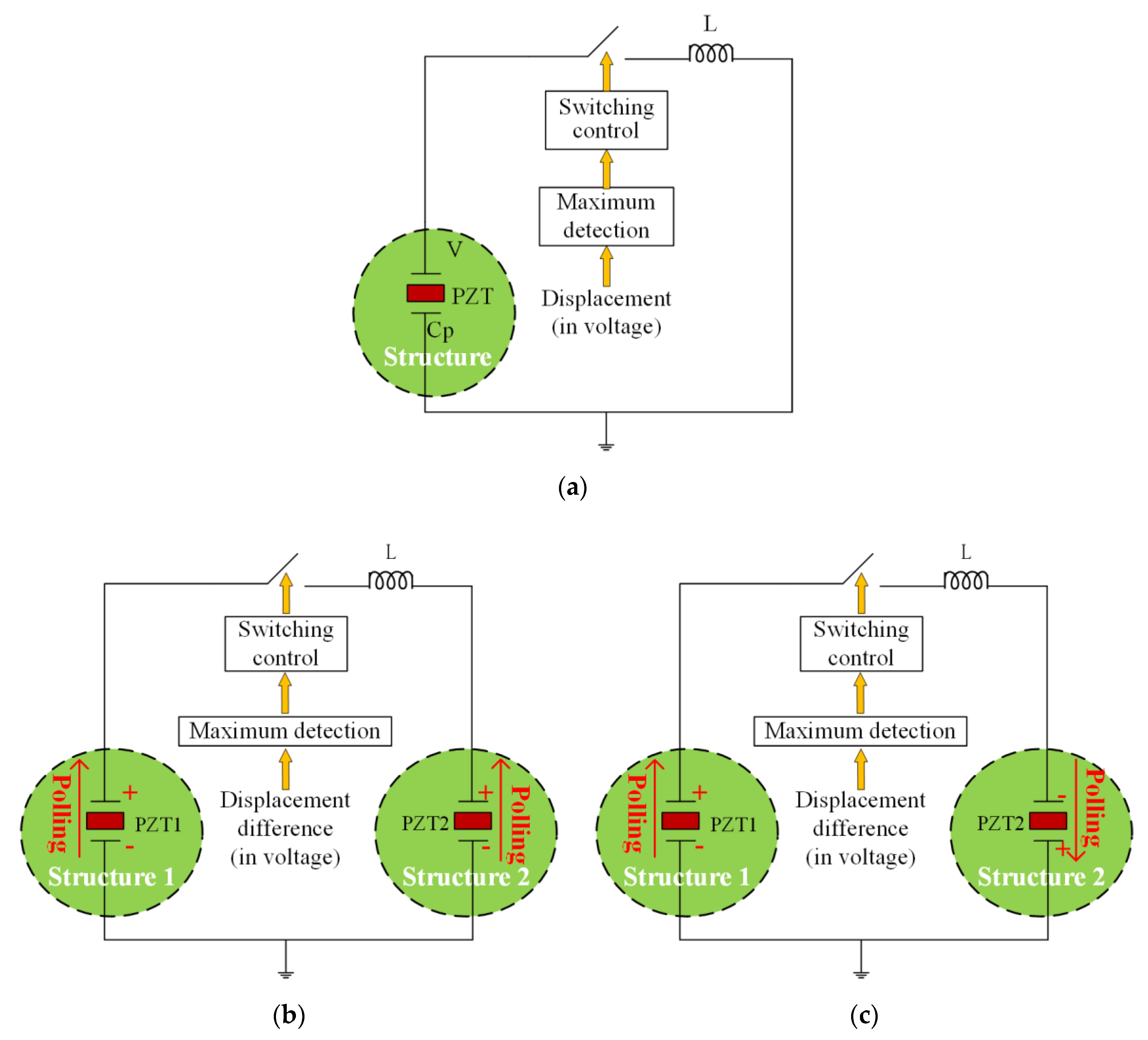
Figure 1. The schematic plots of (a) the conventional synchronized switching damping inductance (SSDI), (b) the dual-connected SSDI with PP (positive-to-positive) connection and (c) the dual-connected SSDI with PN (positive-to-negative) connection.
Applsci 10 01478 g001
Figure 2. Illustration of the voltage-displacement hysteresis loop of SSDI.
Applsci 10 01478 g002
Figure 3. A 2-DOF (degree-of-freedom) mechanical system with dual-connected SSDI.
Applsci 10 01478 g003
Figure 4. Steady-state response of the nonlinear force of dual-connected SSDI and the relative displacement: (a) signal plotted in time domain; (b) the force-displacement hysteresis loop.
Applsci 10 01478 g004
Figure 5. Nonlinear force of dual-connected SSDI in different voltage inversion factor ( γ ).
Applsci 10 01478 g005
Figure 6. Vibration reduction performance of the dual-connected SSDI (PP) with respect to the phase difference: (a) amplitude of x1 and x2 DOFs with respect to the phase difference; (b) steady-state response of x1 and x2 when the phase difference of excitation is 180 degree.
Applsci 10 01478 g006
Figure 7. Frequency response function of the system with and without the dual-connected SSDI (PP).
Applsci 10 01478 g007
Figure 8. The implementation of the SSDI circuit: (a) the circuit board for the switching control; we also put a resistor and a coin (1 CNY) into the photo to illustrate the size of the board; (b) the employed inductor in comparison with the traditional winding coin inductor; (c) the schematic plot of the electric board.
Applsci 10 01478 g008
Figure 9. Setup of the single-beam test rig: (a) the schematic plot; (b) the photo of the test rig, where the red part is the actuator, and the clamping is realized by two bolts.
Applsci 10 01478 g009
Figure 10. Setup of the double-beam test rig: (a) the schematic plot; (b) the photo of the test rig where each beam is individually excited; (c) the auxiliary equipment.
Applsci 10 01478 g010
Figure 11. Sweeping frequency waterfall of the beam with open-circuit condition.
Applsci 10 01478 g011
Figure 12. Photos of the two-beam test rig: (a) evolution of the voltages on PZT1 (50 Hz) with and without SSDI; (b) voltage-responses of PZT1 and PZT2 with SSDI shunt. The voltage of PZT2 is used an indicator of the beam’s displacement.
Applsci 10 01478 g012
Figure 13. Displacement comparison curves (indicated by the voltage of PZT2) in time domain with and without SSDI (50 Hz).
Applsci 10 01478 g013
Figure 14. Comparison of displacements in three cases (50 Hz, phase difference 180 degree).
Applsci 10 01478 g014
Figure 15. Comparison of damping-effect in three cases (white noise, phase difference: 180 degree): (a) displacement response in time domain; (b) frequency response.
Applsci 10 01478 g015
Figure 16. Response vs. phase difference (degree) of excitation.
Applsci 10 01478 g016
Figure 17. Lumped parameter model of blisk with dual-connected SSDI shunt.
Applsci 10 01478 g017
Figure 18. The targeted vibration problem of a bladed disk: (a) the mistuned pattern of the blade stiffness; (b) response amplitude of 24 blades without SSDI circuit (excited by engine-order E = 3); (c) the response phase of the 24 blades (excited by engine-order E = 3 at the same frequency as (b)).
Applsci 10 01478 g018
Figure 19. Response amplitude of 24 blades in three configurations (tuned, mistuned with and without dual-connected SSDI).
Applsci 10 01478 g019
Figure 20. Standard deviation of blade responses (1—original; 2—with dual-connected SSDI).
Applsci 10 01478 g020
Figure 21. Forced response of the most dangerous blades under single-harmonic excitation (E = 0, 1, 2 respectively).
Applsci 10 01478 g021
Figure 22. Forced response of the most dangerous blades under multi-engine-order excitation (E = 0, 1, 2 at the same time).
Applsci 10 01478 g022
Table 1. Parameters of the aluminum beam.
Parameter (unit)Length (mm)Width (mm)Thickness (mm)Elastic Modulus (Gpa)Poisson’s RatioDensity (kg/m3)
Value200502700.332700
Table 2. Parameters of the piezoelectric patch.
Parameter (unit)Length (mm)Width (mm)Thickness (mm)Elastic Modulus (GPa)Density (kg/m3)Force Factor (N/V)Intrinsic Capacitance (nF)
Value43350.5667650 1.27 × 10 4 20
Table 3. Damping comparison of the double-beam system in three cases (white noise, 180 degree).
Electric Circuits1st-Order Frequency (Hz)Maximum Displacement (mV)2nd-Order Frequency (Hz)Maximum
Displacement * (mV)
Open-circuit50.05164.62803.891
SSDI-PN50.1158280.43.558
SSDI-PP50.1118.5280.42.801
* The displacement is inspected by a collocated PZT patch so the unit is in mV.
Table 4. Non-dimensional parameters of the blisk.
Variables N δ mb δ md γ b γ d γ c γ e γ p α c β c δ fb δ fd
Value2411211.5300.050.01 10 6 0.0510