Article

Fabrication of Natural Flake Graphite/Ceramic Composite Parts with Low Thermal Conductivity and High Strength by Selective Laser Sintering

Hubei Key Laboratory of Hydroelectric Machinery Design & Maintenance, College of Mechanical & Power Engineering, China Three Gorges University, Yichang 443002, China
*
Author to whom correspondence should be addressed.
Appl. Sci. 2020, 10(4), 1314; https://doi.org/10.3390/app10041314
Submission received: 13 January 2020 / Revised: 9 February 2020 / Accepted: 11 February 2020 / Published: 14 February 2020
(This article belongs to the Special Issue Progress in 3D Printing of Materials)

Abstract

:
The 3D graphite/ceramic composite prototyping parts directly prepared by selective laser sintering (SLS) were porous, which led to poor strength and low thermal conductivity. In order to obtain low thermal conductivity and high strength, its thermal conductivity and compressive strength were adjusted by changing the mixture powder composition and adding post-processing. The result showed that the addition of silicon powder in the mixture powder could significantly improve the compressive strength and thermal conductivity. The addition of expanded graphite was beneficial to the formation of the closed pores in the matrix, which slightly reduced the compressive strength but significantly reduced the thermal conductivity. The 3D graphite/ceramic composite part showed an order of magnitude improvement in compressive strength (from 1.25 to 13.87 MPa) but relatively small change in thermal conductivity (from 1.40 to 2.12 W·m−1K−1) and density (from 0.53 to 1.13 g·cm−3) by post-processing. Reasonable mixture powder composition and post-processing were determined and realized the possibility of fabricating a 3D graphite/ceramic composite part with low thermal conductivity but high compressive strength. Furthermore, it could be used for the repeated casting of steel castings, and through the comparative analysis of casting defects, the prepared graphite/ceramic composite part was expected to replace water glass sand mold.

1. Introduction

Natural flake graphite has excellent physical and chemical properties, such as thermal conductivity, electrical conductivity, high-temperature resistance, and corrosion resistance. It is widely used in iron and steel casting, aviation, and aerospace fields [1,2,3,4,5]. It is well known that the natural flake graphite powder is challenging to process and form due to the weak self-adhesive ability and poor formability, so the value of natural flake graphite needs to be realized by proper forming technology. At present, hot pressing and cold pressing are the main processes for forming natural flake graphite [6,7]. The graphite blocks, prepared by hot pressing at 2773 K with natural graphite powder and chopped carbon fibers as raw materials and asphalt as a binder, have proper bending and compressive strength perpendicular to the direction of graphite layer, up to 39.6 MPa and 65.5 MPa, respectively, with 8 wt % chopped carbon fibers [8]. The thermal conductivity of the graphite bulk composites, prepared by uniaxial cold compression molding using natural flake graphite powder, synthetic graphite powder as the raw material, and liquid phenolic resin as its binder, is measured by the Xenon Flash Method to be 19–30 W·m−1K−1 in the range of 100–1000 ℃ [9]. However, the simple graphite product can be made by the above processes, but the complex one can not. The emergence of selective laser sintering (SLS) makes it possible to obtain complex structure graphite parts with natural flake graphite as the raw material.
SLS is a kind of rapid prototyping technology that is widely used to fabricate the complicated preforms or parts with the powder or powder that can bond each other under the hot action during the laser-scanning process. There are a wide range of materials available for selective sintering, including paraffin powder, plastic powder, metal powder, and ceramic powder. For example, according to Chen et al. [10], the graphite/phenolic resin composite bipolar plate for fuel cells can be prepared by SLS with phenolic resin and natural flake graphite, which has been successfully applied in industrial production. Our previous study showed that the effects of process parameters such as laser power, scan speed, scan spacing, and layer thickness on the mechanical properties of SLS graphite parts and pointed out that the bending strength of samples directly formed by SLS can reach 2–3 MPa when the laser power is 20 W, scan speed is 2000 m/s, scan spacing is 0.1 mm, and layer thickness is 0.15 mm [11]. These composite parts formed with graphite/phenolic resin have a typical porous structure, and this porous structure can improve the thermal isolation (approximately 0.73 W.m−1K−1) but reduce the strength (compressive strength approximately 2.1 MPa and flexural strength approximately 2.5 MPa), so it is difficult to fabricate parts meeting both functional and structural requirements directly by the SLS process.
In order to solve the contradictory influence of porous structure on thermal performance and structural performance, the related research work has been mainly carried out from the following two aspects: mixture powder formula composition and post-treatment process. Guo et al. [12,13] found that when the mixture powder composition is 45 vol.% of natural flake graphite, 10 vol.% of carbon fiber, 10 vol.% of synthetic graphite, and 35 vol.% of binder, the comprehensive performance of the fuel cell composite bipolar plate prepared by SLS is similar to that of the bipolar plate prepared by hot pressing. Chen et al. [10] found that the infiltration of the preform sintered by SLS in liquid epoxy resin after carbonization can greatly improve the mechanical properties such as the bending strength up to 50 MPa, but it had little effect on the electric conductivity. Kaushik Alayavalli and David L. Bourell [14] also conducted related research.
In this paper, 3D graphite/ceramic composite parts were fabricated by SLS. The thermal conductivity and compressive strength of 3D graphite/ceramic composite parts prepared by different materials were compared. Meanwhile, the effects of the post-treatment process such as including vacuum pressure infiltration phenolic resin solution, carbonization, vacuum pressure-infiltrated silica sol solution, and high-temperature sintering on the microstructure, thermal conductivity and compressive strength of 3D graphite/ceramic composite parts were studied. Finally, the 3D graphite/ceramic composite parts with low density, high strength, low thermal conductivity, and excellent thermal stability were prepared by adjusting the composition and the post-treatment processes.

2. Materials and Experiments

2.1. Materials

The mixture powder used for SLS forming of graphite preforms were prepared by ball milling with the following four raw materials: natural flake graphite, expanded graphite (EG), silicon powder, and phenolic resin powder. Natural flake graphite and EG were purchased from Qingdao Xinghua Graphite Products Co., Ltd. and had a size of 45–100 µm and 150–200 µm, respectively. Silicon powder, served as the reinforcing phase, was purchased from Sinopharm Chemical Reagent Co., Ltd. and had an average size of 75 µm and a mass purity of 99.5%. The phenolic resin powder (SG-3130) used as a binder in SLS process was purchased from Shanghai Aotong Industrial Co., Ltd. and had an average size of 75µm. Phenolic resin solution with a density of 1.16 g·cm−3 was used to infiltrate into the porous networks of graphite preforms. Silica sol solution with a density of 1.20 g·cm−3 was used to infiltrate into the porous networks of carbonized parts.

2.2. Fabrication Process

The graphite preforms were prepared by sintering mixture powder with a HK S500 selective laser sintering machine (provided by Wuhan Huake 3D Technology Co., Ltd., Wuhan, China), and the process parameters were as follows: fill power 17 W, fill speed 2500 mm/s, fill spacing 0.1 mm, layer thickness 0.1 mm, preheating temperature 40 ℃, laser spot diameter 0.4 mm, adopting contour scanning mode. The post-treatment of the graphite preforms included four processes: vacuum pressure infiltration of phenolic resin solution, carbonization, vacuum pressure infiltration of silica sol solution, and high-temperature sintering. The fabrication process of 3D natural flake graphite/ceramic composite parts is shown in Figure 1. The vacuum pressure infiltration was to put the graphite preforms into the vacuum infiltration machine, vacuum to below 100 Pa, add the phenolic resin solution with the viscosity of 1000 mPa.s (the mass fraction is 30 wt %, the density is 1.06 g.cm−3), soak for 15 min, take out to clean the surface, and then dry in the oven at 60 ℃ for curing. These solidified parts were carbonized in NT-ZKTH-50-1500 vacuum carbonization furnace (Made in Changsha Nuotian Electronic Technology Co., Ltd.) by heating from room temperature to 200 °C at 60 °C/h, then to 600 °C at 30 °C/h, and then to 800 °C at 60 °C/h and holding for 1 h and finally cooling to room temperature. The carbonized parts were followed by vacuum pressure infiltration in silica sol solution (the mass fraction is 30 wt %, the density 1.20 g.cm−3, and the average particle size of SiO2 8–15 nm) with a vacuum degree of less than 100 Pa for 10 to 20 min and drying. Finally, high-temperature sintering was carried out under the protection of nitrogen. The temperature was increased from room temperature to 100 ℃ at 60 ℃/h, then to 1100 ℃ at 240 ℃/h, then to 1500 ℃ at 120 ℃/h and kept for 3 h, and then cooled to room temperature to attain the final sintered parts.

2.3. Experiments

The samples were divided into three groups according to the mass ratio of the four components mentioned above and shown in Table 1. To obtain the mixture powder with uniform distribution of each component, the ball milling process lasted for 4 h. The graphite preforms were prepared by SLS, and the effects of silicon powder and expanded graphite on properties were analyzed by comparing the test results of samples obtained by carbonization and high-temperature sintering, respectively. The influence of vacuum pressure infiltration in phenolic resin solution on the properties was studied based on the test results of the samples prepared by 3# mixture powder. In view of the poor compressive strength caused by new pores emerged in carbonization, the carbonized samples were infiltrated in silica sol solution under vacuum pressure, and the influence of infiltration times in silica sol solution on the properties of the samples after high-temperature sintering was also studied.

2.4. Characterization

The density and open porosity of the samples were tested according to the vacuum method in GB/T 24529-2009. The microstructure and morphology of the samples were observed and analyzed by JSM-7500F cold field emission scanning electron microscope. The phase composition of the samples was analyzed by RIGAKU Ultima IV X-ray diffractometer. The size and distribution of pores in samples were measured by American Micromeritics Auto-Pore IV 9510 mercury porosimeter. The DRE-III thermal conductivity meter was used to measure the thermal conductivity of the samples at room temperature with the dimension of Ø50 mm × 15 mm. To measure the compressive strength, the samples with the size of Ø40 mm × 40 mm were loaded uniformly and without impact at 5 mm/min with a WDW-100E micro control electronic universal testing machine (face to face), and five effective measurement results for each group were taken.

3. Results and Discussion

3.1. Effect of Mixture Powder Composition on Properties

3.1.1. Silicon Powder

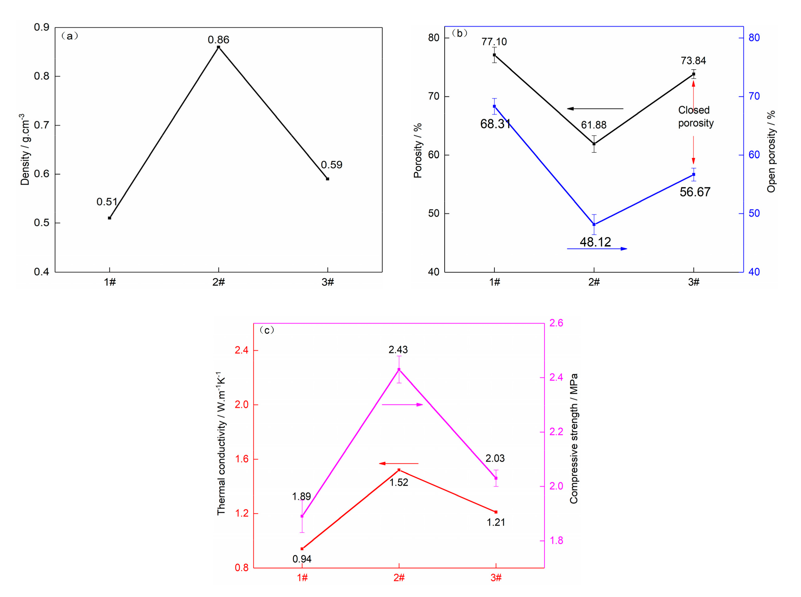
Samples 1#, 2#, and 3#, as shown in Table 1, were obtained by carbonizing and then high-temperature sintering. The porosity and open porosity, thermal conductivity, and compressive strength and density of the samples are shown in Figure 2. Compared with the 1# sample, due to the addition of silicon powder with a mass ratio of 24, the density of the 2# sample increased slightly from 0.51 to 0.59 g·cm−3, the compressive strength increased from 1.89 to 2.43 MPa with an increment of 28.57%, and the thermal conductivity increased from 0.94 to 1.52 W·m−1K−1 with an increment of 61.7%.
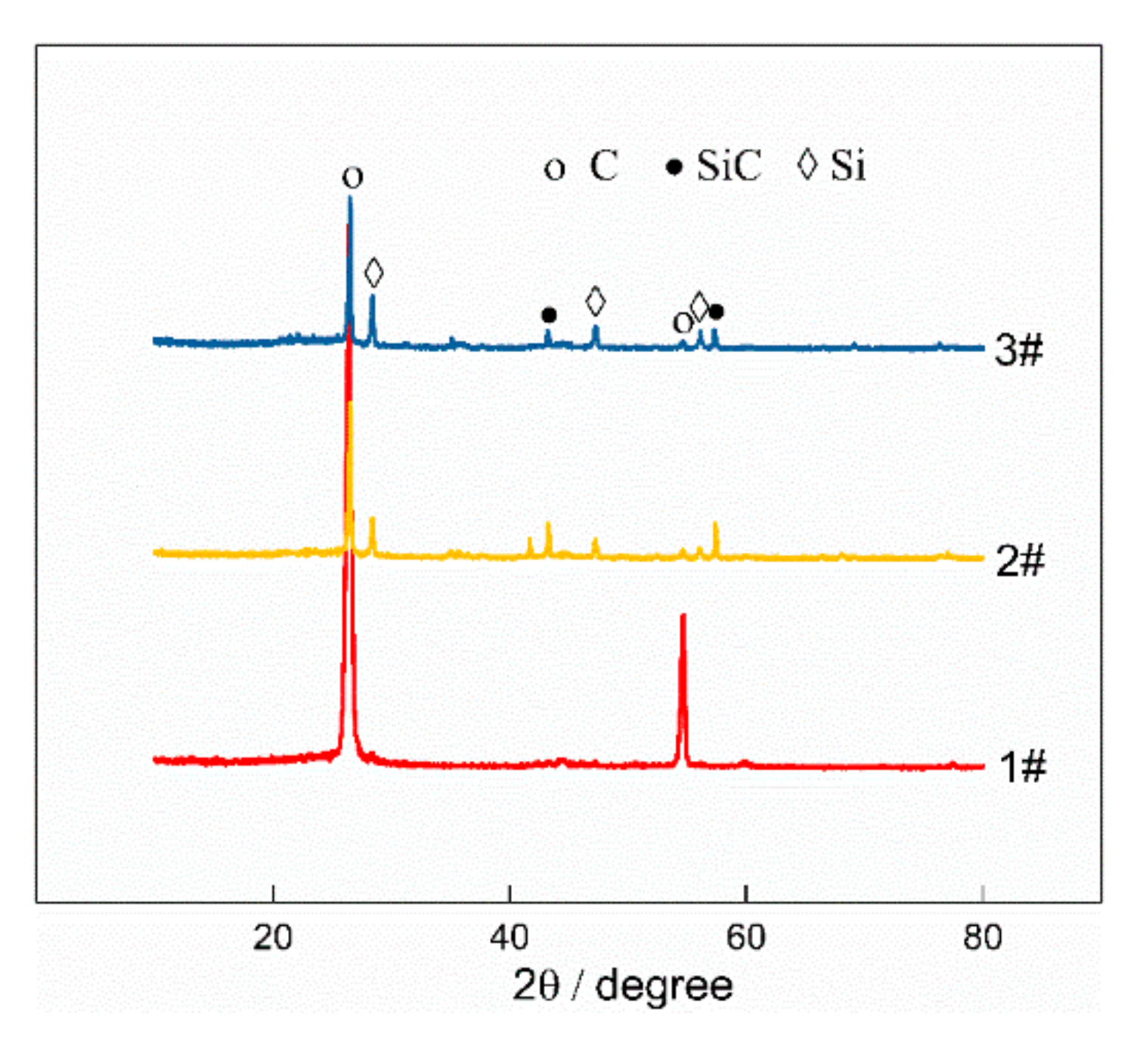
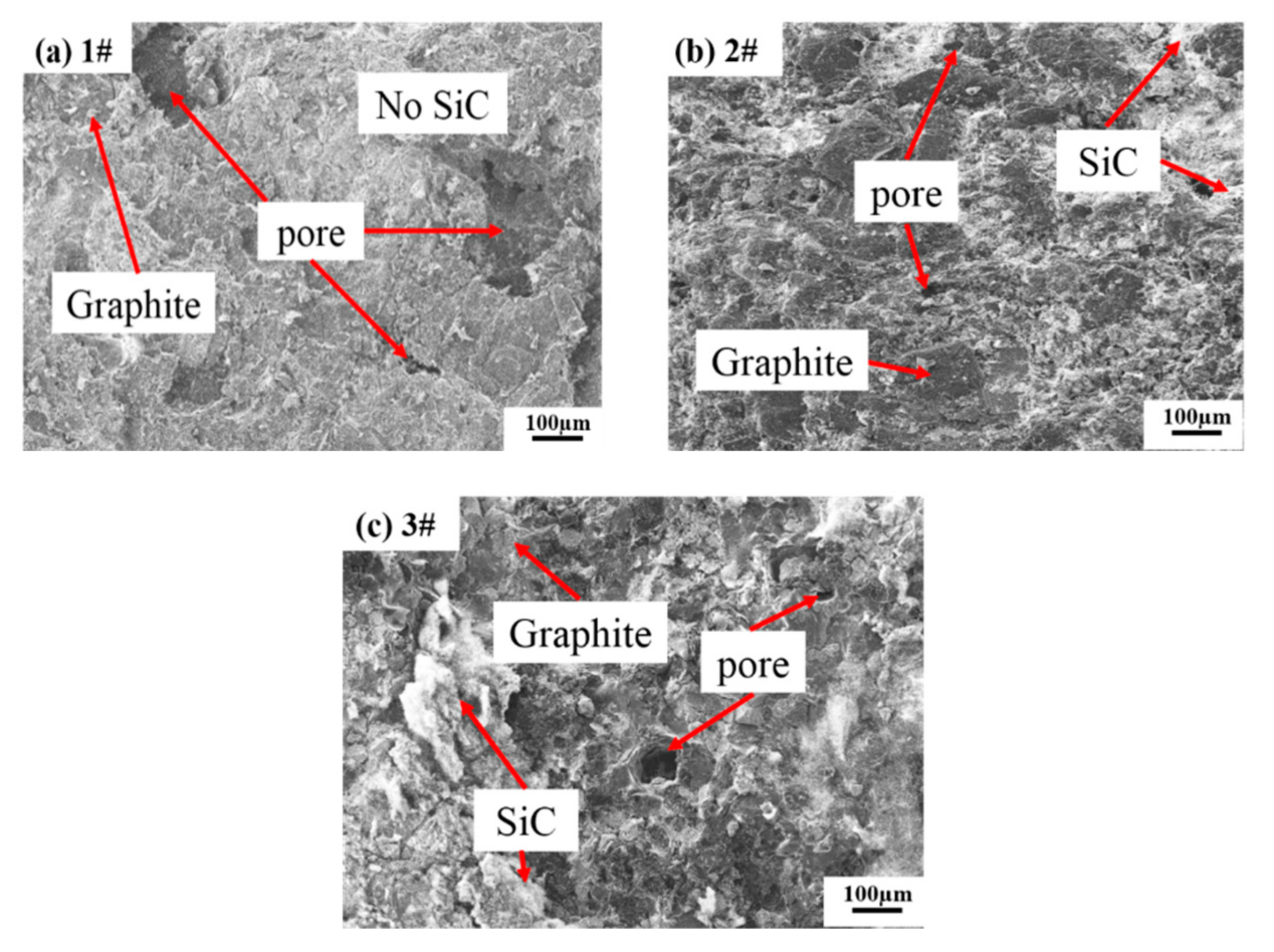
Figure 3 shows the X-ray diffraction pattern of the materials from the three samples mentioned above. It can be seen that there was a small amount of unreacted silicon powder, but the silicon carbide (SiC)-reinforced phase formed during the high-temperature sintering. 1# did not contain silicon powder, so there was no silicon carbide peak in the XRD pattern. 2# and 3# contain the same content of silicon powder, and 3# contains 1% expanded graphite, which resulted in a slight difference in diffraction peak strength. It should be noted that the formation of SiC was accompanied by 30% volume expansion, which significantly reduced the porosity from 68.31% to 48.12% and then greatly increased the geometric density. Compared with the samples of the 1# mixture powder, fewer pores existed inside the samples with the 2# and 3# mixture powders. The microstructure and morphology of these samples are shown in Figure 4. It confirmed that the excellent effect of bonding, pores filling, and strengthening of SiC formed from silicon powder in high-temperature sintering led to the increase of thermal conductivity and compressive strength [15,16,17,18].

3.1.2. Expanded Graphite

By comparison of the 2# and 3# samples, it can be seen that the addition of expanded graphite with mass ratio of 1% caused the decrease of density, compressive strength and thermal conductivity from 0.86 to 0.59 g·cm−3, 2.43 to 2.08 MPa, and 1.52 to 1.21 W·m−1K−1, respectively, and the porosity increased from 61.88% to 73.84%, which can be attributed to the formation of new pores due to the expansion of expanded graphite as the temperature rises to over 300 °C.
The effect of pores on strength and thermal conductivity varies according to the form of the pores. Although the open pores and closed pores are the same in topological structure, the open pores are a form of multiple closed pores connected with each other, which not only weakens the strength of the structure due to the reduction of connection points in the structure but also enhances the convective heat conduction due to the expansion of pore space, thus improving the thermal conductivity of the structure. In comparison, the closed pores do not destroy the reliable connection between the pores to avoid weakening the strength. Moreover, the closed pores can reduce the thermal conductivity of the whole structure by blocking the convective heat conduction [19,20]. Compared with the 2# sample, with the addition of a mass ratio of expanded graphite, the closed porosity of the 3# sample increased by about 3.41% from 13.76% to 17.17%, as shown in Figure 2b. Accordingly, the compressive strength and thermal conductivity decreased by 16.46% and 20.39%, respectively, which means the addition of a small amount of expanded graphite can effectively reduce the strength and thermal conductivity of the samples. There are still some pores and silicon carbide formed in the 2# and 3# samples. Compared with the 2# sample, the 3# sample has fewer pores and the surface looks smoother due to the volume expansion of expanded graphite, as shown in Figure 4b,c. The influence of expanded graphite on the strength is less than that on the thermal conductivity, which provides the possibility of the preparation of 3D graphite/ceramic composite parts with both high strength and low thermal conductivity [21,22,23].

3.2. Effect of Post-Processing on Properties

3.2.1. Vacuum Pressure Impregnation of Phenolic Resin Solution and Carbonization

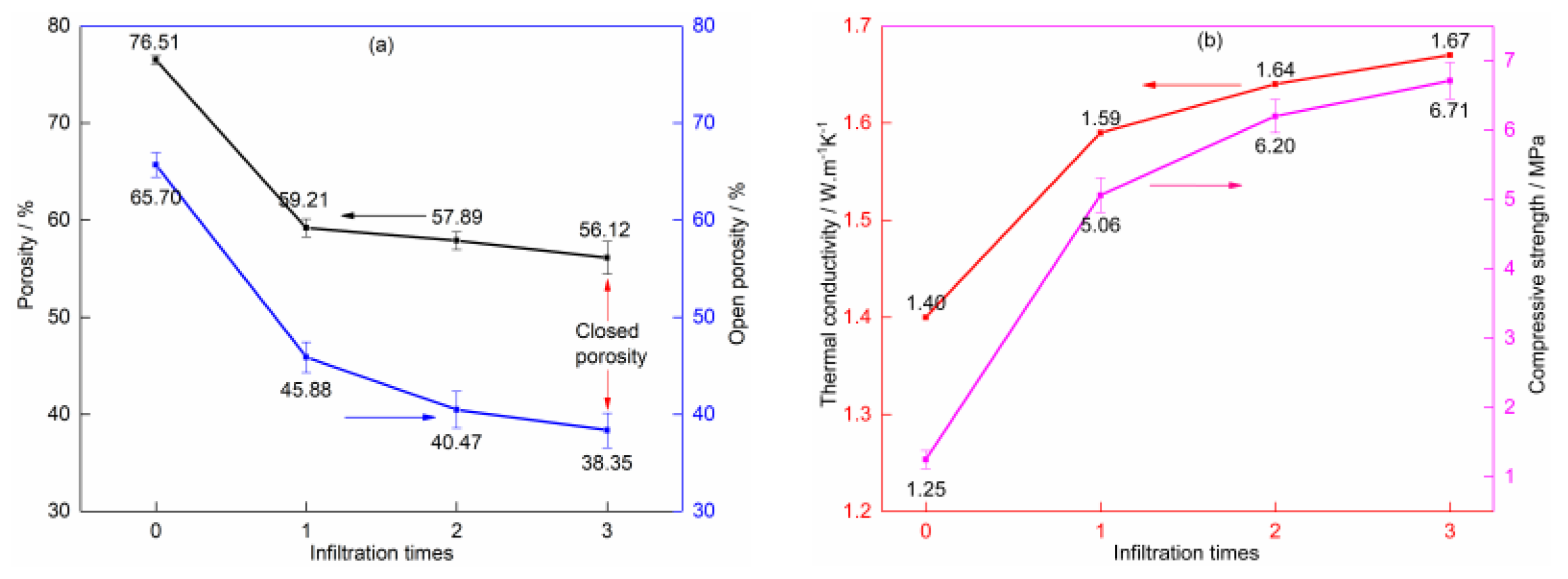
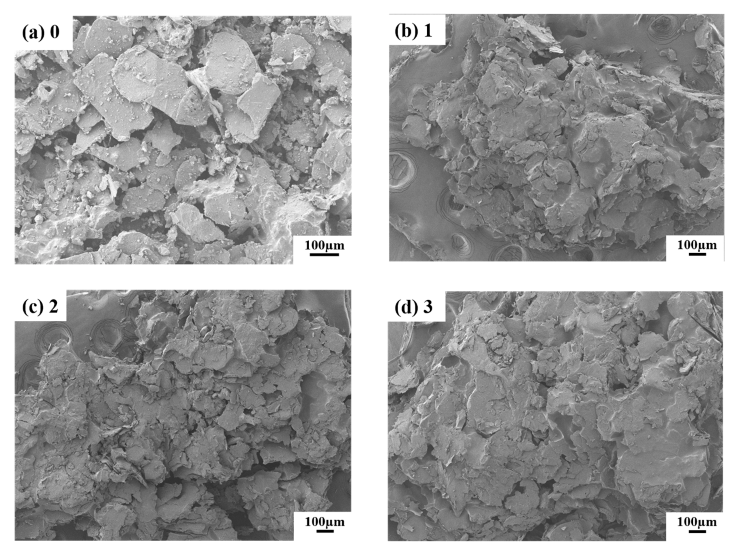
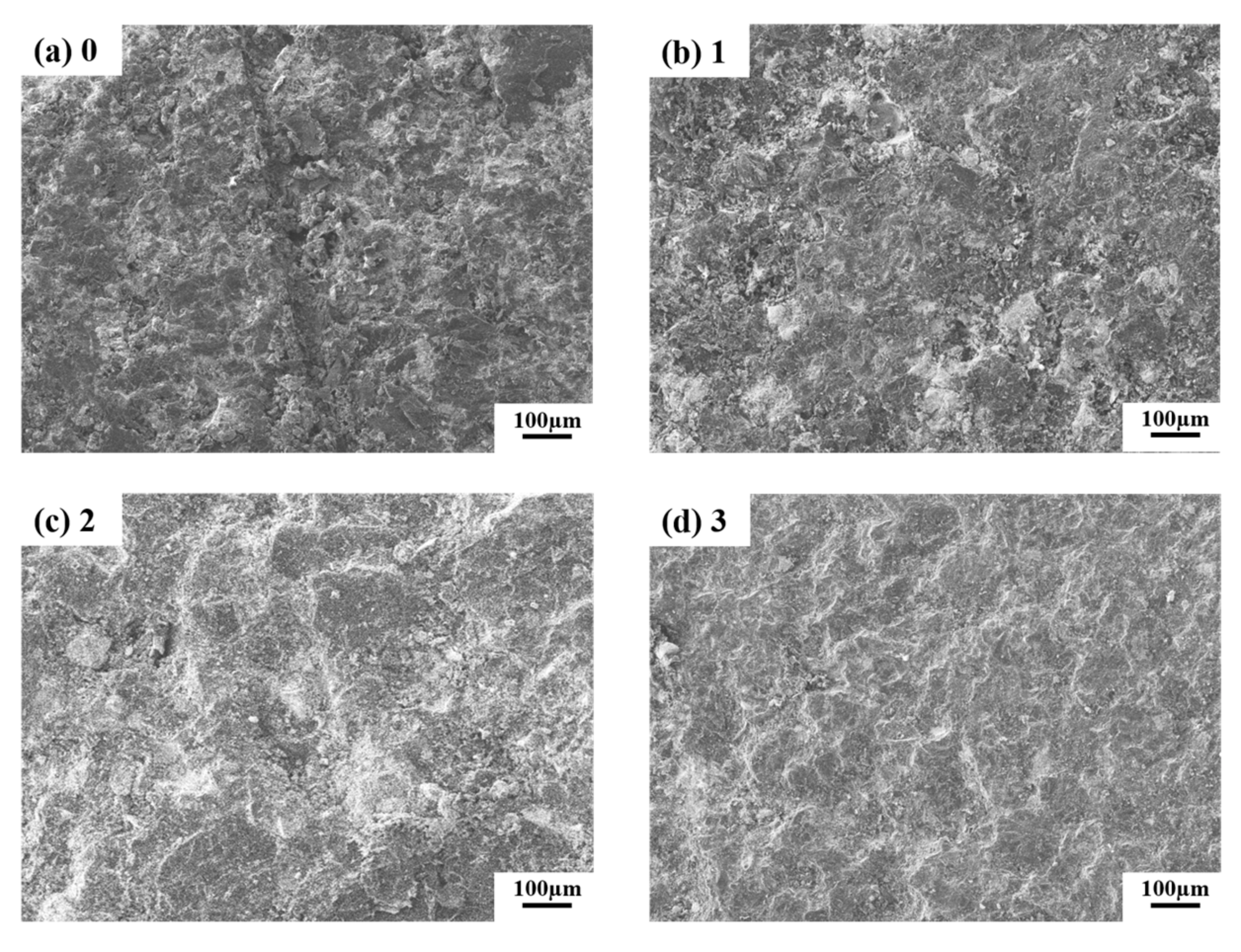
Figure 5 shows the comprehensive properties of carbonized graphite preforms after vacuum pressure infiltration in phenolic resin solution (select 3# mixture powder). The porosity and open porosity of the samples without vacuum pressure infiltration are 76.51% and 65.70%, respectively, and these are loose and high porosity characteristics, which may account for the lower thermal conductivity (1.40 W·m−1K−1) and compressive strength (1.25 MPa). However, the thermal conductivity and compressive strength of the carbonized samples after vacuum pressure infiltration are improved to a certain extent. After three times the vacuum infiltration in phenolic resin solution, the porosity and the open porosity of the samples were decreased 20.39% (from 76.51% to 56.12%) and 27.35% (from 65.70% to 38.35%), respectively compared with those without infiltration (Figure 5a). The porosity decreased by vacuum pressure infiltration in phenolic resin solution, which was also confirmed by the SEM images shown in Figure 6.
The graphite preforms were formed with graphite flakes that bonded with each other by resin during the process of SLS. Although the resin content of the mixture powder used for 3D printing is high (30 wt %), only a small amount of molten resin plays a role in bonding during the laser rapid scanning process, so the strength of SLS preforms is low (1.25 MPa). In addition, during the SLS process, the mixture powder spread freely under the action of gravity, and the loose accumulation structure between powder remains after SLS, so the preform has a high porosity (76.51%). The porous microstructure was also observed by SEM image, as shown in Figure 6a. By vacuum pressure infiltration, the internal porous structure is filled, and the graphite flakes are coated by liquid phenolic resin. The filling and binding of phenolic resin account for the increase in density and compressive strength of the samples.
In the process of carbonization, the phenolic resin (approximately 70–80 wt %) is heated at high-temperature and transformed from organic binder to inorganic binder (glass carbon) [8], which has higher strength than a phenolic resin binder and consequently results in the higher compressive strength of carbonized samples. Figure 7 shows the glass carbon binder bridge formed by the phenolic resin binder during the process of carbonization in samples without infiltration. As a result of vacuum pressure infiltration, the more resin infiltrated into the pores, the more glass carbon converted, the lower the porosity, and the greater the strength and density of the samples [24].
After the first vacuum pressure infiltration, the strength and density increased significantly by 304.8% (from 1.25 MPa to 5.06 MPa) and 73.58% (from 0.53 g·cm−3 to 0.92 g·cm−3), respectively, while the thermal conductivity only increased by 13.57%. The second vacuum pressure infiltration caused an increase in compressive strength, density, and thermal conductivity of about 22.53%, 5.43%, and 3.14%, respectively, and the third infiltration resulted in the increment of no more than approximately 2% in density and thermal conductivity, while the strength increment is only about 8.23% and not significant compared with the first immersion (Figure 6b). The results show that after infiltration twice, there is little potential to adjust the strength, porosity, and thermal conductivity of the samples by continuous infiltration. Therefore, in view of the fact that more than two times of vacuum pressure infiltration in phenolic resin solution has no obvious effect on the structure and properties, two times of vacuum pressure infiltration is chosen as the best scheme.

3.2.2. Vacuum Pressure Infiltration of Silica Sol Solution and High-Temperature Sintering

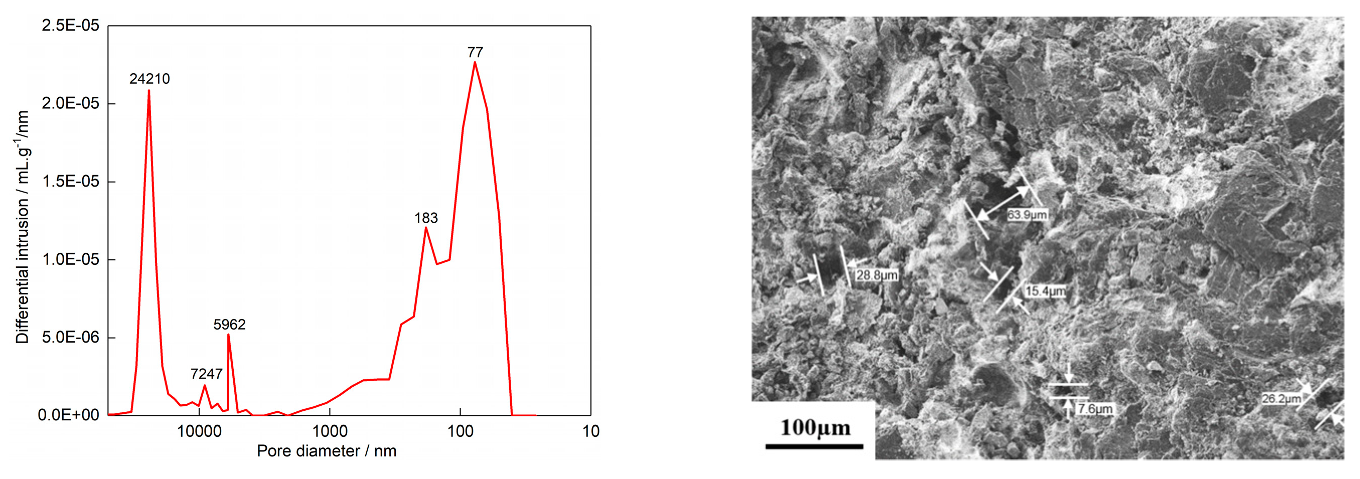
Figure 8 shows the pore size distribution and micromorphology of the carbonized samples after twice vacuum pressure infiltration in phenolic resin solution. There are still many macropores with an average pore diameter of 16.24 μm after carbonization. These pores provide favorable space for the filling of silica sol solution due to the suitable size of nano-silica powder (with an average size of 8–15 nm) contained in the sol. Therefore, by infiltrating silica sol solution under vacuum pressure, the pores in carbonized samples can be effectively filled with silica sol solution, so that the strength of the samples can be further improved after subsequent sintering [25].
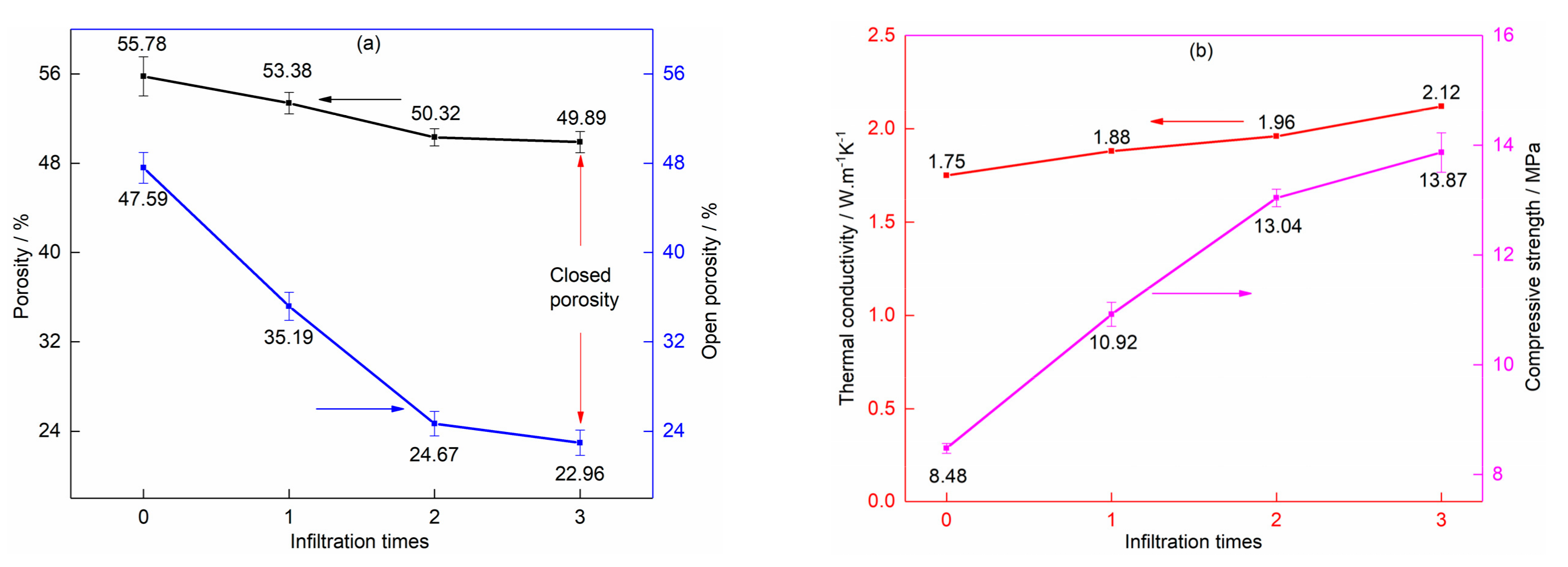
Before vacuum pressure infiltration of silica sol solution, the sample was infiltrated twice in phenolic resin solution and carbonized. The carbonized sample was infiltrated in the silica sol solution under vacuum pressure and then sintered at high-temperature. Drying treatment was carried out before repeated infiltration in silica sol solution or high-temperature sintering. The properties and porosity of sintered samples with different times of infiltration in silica sol solution are shown in Figure 9.
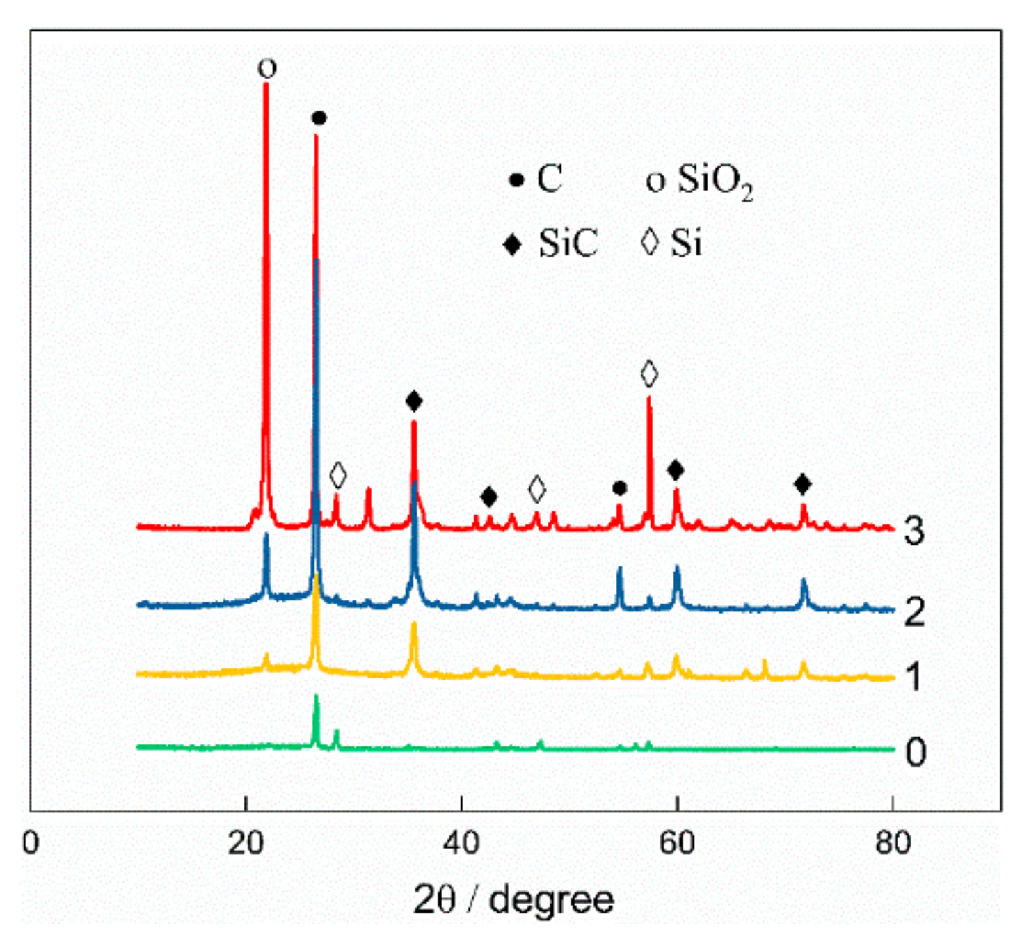
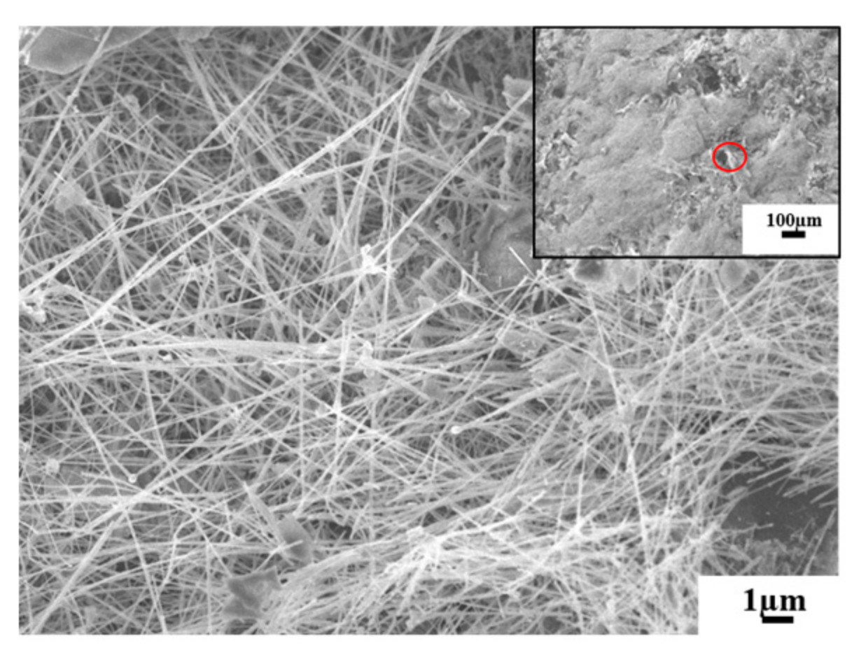
In the high-temperature sintering process, when the sintering temperature is over 1440 ℃, the molten silicon reacts with the active glass carbon carbonized by phenolic resin to form the SiC whisker reinforcement phase, which is confirmed by the XRD pattern in Figure 10 and SEM image in Figure 11. SiC has high strength, good thermal conductivity, and excellent interface bonding with graphite, and it acts as the strengthening phase to enhance the strength of the matrix. Enough SiC whiskers strongly linked by mechanical contact can be formed a three-dimensional framework, which can effectively improve the strength and thermal conductivity of the sample [26,27]. With the increase of the number of infiltration times of silica sol solution, the intensity of the diffraction peak of silicon carbide was higher; when the silica sol solution was infiltrated three times, the reaction was incomplete due to insufficient active carbon source, leaving more silicon and silicon dioxide. After three times of vacuum pressure infiltration in silica sol solution, the strength and thermal conductivity of the sintered sample are increased by 63.56% and 21.14%, respectively. The results are consistent with the above analysis [28,29].
The porosity of the samples can be effectively reduced by the filling of silica sol solution into open pores in vacuum pressure infiltration, which can be confirmed by the SEM microstructure in Figure 12. However, the closed pores can not be infiltrated into by silica sol solution, so the porous structure can not be eliminated completely after sintering at high temperature. Besides, the porosity can be reduced to some extent because of the volume expansion of 35% accompanied by the formation of SiC whiskers, as the new tiny pores can be caused by volume shrinkage of the silica sol solution infiltrated into the open pores due to the loss of liquid phase (such as water or organic solvent) or thermal stress during the subsequent drying and sintering process [30].
The results of the porosity test show that after three times of sintering, the porosity and open porosity are reduced by 5.89% and 24.63%, respectively, but the closed porosity is increased by 18.74%, which shows that the new tiny pores produced in drying and sintering are mainly closed pores. The porous structure, especially the closed pores, plays a vital role in ensuring the low thermal conductivity of the sample. Although the porosity of the sample is gradually reduced by several rounds of vacuum pressure infiltration in silica sol solution, the effect of subsequent infiltration is weakened for the decrease of average size of pores and the increase of closed porosity caused by drying after infiltration. The porosity of the sintered sample with three rounds of infiltration in silica sol solution decreased by less than 1%—in other words, it was almost unchanged—and the density, compressive strength, and thermal conductivity increased by 1.80%, 6.37%, and 8.16%, respectively. Compared with the previous two infiltrations, the change of samples in structure, strength, and thermal properties is not significant.
Moreover, the compressive strength of 3D graphite/ceramic composite parts after sintering shows an order of magnitude improvement over the 3D graphite parts directly fabricated by SLS (from 1.25 to 13.87 MPa), while the thermal conductivity and density have relatively small change (from 1.40 to 2.12 W·m−1K−1 and 0.53 to 1.13 g·cm−3, respectively). The fabrication scheme developed in this paper allows the manufacture of 3D graphite/ceramic composite parts with low thermal conductivity but high mechanical properties.

4. Application Examples

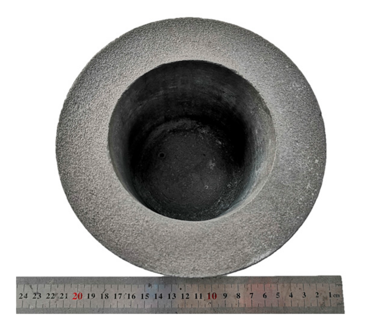
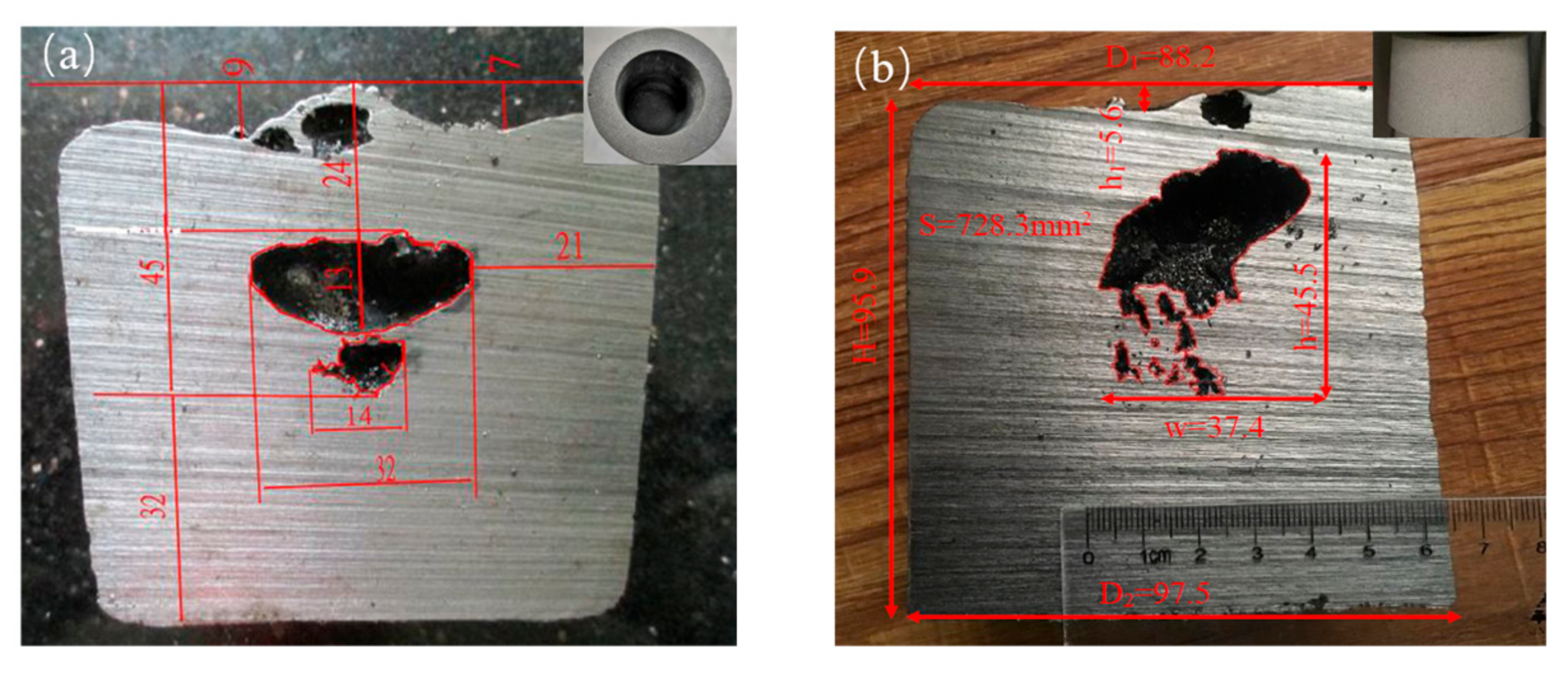
Adding 24% silicon powder and 1% expanded graphite to the graphite/phenolic resin mixture powder, the 3D graphite/ceramic composite mold shown in Figure 13 was quickly prepared by SLS combined with post-processing, and its comprehensive properties are shown in Table 2. The 3D graphite/ceramic mold has excellent combination properties of low density (<1.20 g·cm−3), high compressive strength (>10 MPa), low thermal conductivity (<2 W·m−1K−1), and high-temperature resistance (>1550 ℃). Comparative analysis of the location of defects in graphite–ceramic composite mold and water glass sand mold casting is shown in Figure 14. It was found that the depth of defects is near, indicating that their thermal insulation properties are similar, and compared with production costs (Table 2), which realized the possibility of using graphite–ceramic composite molds to replace the water glass sand molds in casting under certain conditions.

5. Conclusions

A general strategy has been presented for the fabrication of 3D graphite/ceramic composite parts with a combination of low thermal conductivity and high strength. The mixture powder was modified by adding silicon powder and expanded graphite for the printing of preforms via SLS. The addition of 24% silicon powder resulted in an increase of thermal conductivity and compressive strength by 61.70% and 28.57%, respectively. The amount of 1% EG caused a decrease of thermal conductivity and compressive strength by 25.62% and 16.82%, respectively. The porous structure in preforms could be filled by phenolic resin in the process of vacuum pressure infiltration. The conversion of phenolic resin into glass carbon in the subsequent carbonization process improved the strength and thermal conductivity. The silica sol solution was infiltrated after carbonization, and the silicon carbide reinforcing phase was generated during high-temperature sintering, thereby significantly improving the strength and thermal conductivity of composite parts.
The fabrication scheme developed in this paper allowed the manufacture of thermal-conductivity-tunable 3D graphite/ceramic composite parts and realized the possibility of fabricating 3D graphite/ceramic composite parts with low thermal conductivity but high mechanical properties that met the demand for the potential of many engineer fields.

Author Contributions

This paper was accomplished based on collaborative work of the authors. K.C. performed the experiments, analyzed the data, interpreted the experimental results, and wrote the paper. Y.L., C.R. and Y.S. contributed to design and perform the experiments. H.W. and C.H. supervised the entire research progress. All authors have read and agreed to the published version of the manuscript.

Funding

This research was funded by the National Natural Science Foundation of China (No.51575313), the Major Technological Innovation Project of Hubei Science and Technology Department (No.2019AAA164), Hubei Key Laboratory of Hydroelectric Machinery Design & Maintenance (No.2018KJX07) and Open Research Fund for the State Key Laboratory of Mechanical Manufacturing System Engineering, Xi’an Jiaotong University (No.sklms2018001).

Conflicts of Interest

The authors declare no conflict of interest.

References

  1. Wang, Q.; Han, X.H.; Sommers, A.; Park, Y.; T’ Joen, C.; Jacobi, A. A review on application of carbonaceous materials and carbon matrix composites for heat exchangers and heat sinks. Int. J. Refrig. 2015, 35, 7–26. [Google Scholar] [CrossRef]
  2. Jian-Feng, H.; Xie-Rong, Z.; He-Jun, L.; Xin-Bo, X.; Ye-wei, F. Influence of the preparation temperature on the phase, microstructure and anti-oxidation property of a SiC coating for C/C composites. Carbon 2004, 42, 1517–1521. [Google Scholar] [CrossRef]
  3. Toyoda, M.; Inagaki, M. Heavy oil sorption using exfoliated graphite new application of exfoliated graphite to protect heavy oil pollution. Carbon 2000, 38, 199–210. [Google Scholar] [CrossRef]
  4. Findlay, J.R.; Laing, T.F. The diffusion of fission products from graphite. J. Nucl. Mater. 1962, 7, 182–191. [Google Scholar] [CrossRef]
  5. Dmitriev, A.V.; Ershov, A.A. Cracking on the Compaction of a Model Composition Based on Natural Flake Graphite and Binder Pitch. Solid Fuel Chem. 2018, 52, 260–268. [Google Scholar] [CrossRef]
  6. Mathur, R.B.; Dhakate, S.R.; Gupta, D.K.; Dhami, T.L.; Aggarwal, R.K. Effect of different carbon fillers on the properties of graphite composite bipolar plate. J. Mater. Process. Technol. 2008, 203, 184–192. [Google Scholar] [CrossRef]
  7. Yang, X.; Yang, W.; Fan, J.; Wu, J.; Zhang, K. Effects of molding on property of thermally conductive and electrically insulating polyamide 6–based composite. J. Thermoplast. Compos. Mater. 2019, 32, 1190–1203. [Google Scholar] [CrossRef]
  8. Zhao, Y.; Liu, Z.; Wang, H.; Shi, J.; Zhang, J.; Tao, Z.; Guo, Q.; Liu, L. Microstructure and thermal/mechanical properties of short carbon fiber-reinforced natural graphite flake composites with mesophase pitch as the binder. Carbon 2013, 53, 313–320. [Google Scholar] [CrossRef]
  9. Magampa, P.P.; Manyala, N.; Focke, W.W. Properties of graphite composites based on natural and synthetic graphite powder and a phenolic novolac binder. J. Nucl. Mater. 2013, 436, 76–83. [Google Scholar] [CrossRef] [Green Version]
  10. Chen, S. Fabrication of PEM Fuel Cell Bipolar Plate by Indirect Selective Laser Sintering. Ph.D. Thesis, The University of Texas at Austin, Austin, TX, USA, 2006. [Google Scholar]
  11. Wu, H.; Sun, Y.; Peng, J.; Huang, C.; Ye, X. Effect of processing parameters on dimensional accuracy and bending strength of graphite flake/phenolic resin powder mixture in SLS process. Proc. Inst. Mech. Eng. Part C J. Mech. Eng. Sci. 2019, 233, 4497–4507. [Google Scholar] [CrossRef]
  12. Guo, N.; Leu, M.C. Effect of different graphite materials on the electrical conductivity and flexural strength of bipolar plates fabricated using selective laser sintering. Int. J. Hydrog. Energy 2012, 37, 3558–3566. [Google Scholar] [CrossRef]
  13. Guo, N.; Leu, M.C. Performance Investigation of Polymer Electrolyte Membrane Fuel Cells Using Graphite Composite Plates Fabricated by Selective Laser Sintering. J. Fuel Cell Sci. Tech. 2013, 11, 011003. [Google Scholar] [CrossRef]
  14. Alayavalli, K.; Bourell, D.L. Fabrication of modified graphite bipolar plates by indirect selective laser sintering (SLS) for direct methanol fuel cells. Rapid Prototyp. J. 2010, 16, 268–274. [Google Scholar] [CrossRef]
  15. Rice, R.W. Comparison of stress concentration versus minimum solid area based mechanical property-porosity relations. J. Mater. Sci. 1993, 28, 2187–2190. [Google Scholar] [CrossRef]
  16. Li, X.; Yan, Q.; Han, Y.; Cao, M.; Ge, C. Fabrication of solid-phase-sintered SiC-based composites with short carbon fibers. Int. J. Miner. Metall. Mater. 2014, 21, 1141–1145. [Google Scholar] [CrossRef]
  17. Han, Y.; Li, Q.; Yan, Q.; Tang, R. Properties of silicon carbide-reinforced graphite composites prepared by a reactive sintering method. Carbon 2015, 86, 374. [Google Scholar] [CrossRef]
  18. Argento, C.; Bouvard, D. Modeling the effective thermal conductivity of random packing of spheres through densification. Int. J. Heat Mass Transf. 1996, 39, 1343–1350. [Google Scholar] [CrossRef]
  19. Liu, R.; Wang, C. Effects of pore-forming agent content on properties of porous 8YSZ ceramics by TBA based gel-casting. Rare Met. Mater. Eng. 2013, 42, 422–425. [Google Scholar]
  20. Paul, R.M.; Morral, J.E. A 3D-Random pore model for the oxidation of graphite with closed porosity. J. Nucl. Mater. 2018, 509, 425–434. [Google Scholar] [CrossRef]
  21. Wu, M.; Huang, H.-X.; Tong, J.; Ke, D.-Y. Enhancing thermal conductivity and mechanical properties of poly (methyl methacrylate) via adding expanded graphite and injecting water. Compos. Part A Appl. Sci. Manuf. 2017, 102, 228–235. [Google Scholar] [CrossRef]
  22. Kim, H.S.; Na, J.H.; Jung, Y.C.; Kim, S.Y. Synergistic enhancement of thermal conductivity in polymer composites filled with self-hybrid expanded graphite fillers. J. Non Cryst. Solids. 2016, 450, 75–81. [Google Scholar] [CrossRef]
  23. Wang, Q.; Li, Y.; Liao, N.; Xu, X.; Sang, S.; Xu, Y.; Wang, G.; Nath, M. Synthesis of boron and nitrogen-doped expanded graphite as efficient reinforcement for Al2O3-C refractories. Ceram. Int. 2017, 43, 16710–16720. [Google Scholar] [CrossRef]
  24. Choe, C.R.; Lee, K.H.; Yoon, B.I. Effect of processing parameters on the mechanical properties of carbonized phenolic resin. Carbon 1992, 30, 247–249. [Google Scholar] [CrossRef]
  25. Soto, C.; García-Rosales, C.; Echeberria, J. Production of porous SiC by liquid phase sintering using graphite as sacrificial phase: Influence of SiO2 and graphite on the sintering mechanisms. J. Eur. Ceram. Soc. 2019, 39, 3949–3958. [Google Scholar] [CrossRef]
  26. Hua, Y.; Bai, S.; Wan, H.; Chen, X.; Hu, T.; Gong, J. Research on controllable synthesis of silicon carbide whiskers and powder on graphite by chemical vapor reaction. J. Mater. Sci. 2019, 54, 2016–2024. [Google Scholar] [CrossRef]
  27. Zhang, X.; Shi, Z.; Zhang, X.; Wang, K.; Zhao, Y.; Xia, H.; Wang, J. Three dimensional AlN skeleton-reinforced highly oriented graphite flake composites with excellent mechanical and thermophysical properties. Carbon 2018, 131, 94–101. [Google Scholar] [CrossRef]
  28. Li, X.; Zheng, M.; Li, R.; Yuan, G.; Zhou, G.; Zhu, X.; Ren, G. Preparation, microstructure, properties and foaming mechanism of a foamed ceramics with high closed porosity. Ceram. Int. 2019, 45, 11982–11988. [Google Scholar] [CrossRef]
  29. Li, X.; Zhou, G.; Yang, Q.; Zhu, X.; Ren, G.; Liu, L. Preparation and performance of electromagnetic wave absorbing foamed ceramics with high closed porosity and gradient SiC distribution. Ceram. Int. 2020, 46, 2294–2299. [Google Scholar] [CrossRef]
  30. Fan, J.; Xu, S. Thermal conductivity and mechanical properties of high density polyethylene composites filled with silicon carbide whiskers modified by cross-linked poly (vinyl alcohol). J. Mater. Sci. Technol. 2018, 34, 185–192. [Google Scholar] [CrossRef]
Figure 1. The fabrication process of 3D natural flake graphite/ceramic composite parts.
Applsci 10 01314 g001
Figure 2. (a) Density; (b) porosity and open porosity; and (c) thermal conductivity and compressive strength of different 3D graphite/ceramic composite parts.
Applsci 10 01314 g002
Figure 3. XRD pattern of different 3D graphite/ceramic composite parts.
Applsci 10 01314 g003
Figure 4. SEM image of different 3D graphite/ceramic composite parts. (a) sample 1#, (b) sample 2#, (c) sample 3#.
Applsci 10 01314 g004
Figure 5. Effect of phenolic resin solution infiltration times on properties: (a) porosity and open porosity; (b) thermal conductivity and compressive strength.
Applsci 10 01314 g005
Figure 6. SEM image of different infiltration times of phenolic resin solution. (a) 0 times, (b) 1 time, (c) 2 times, (d) 3times.
Applsci 10 01314 g006
Figure 7. SEM image of glassy carbon.
Applsci 10 01314 g007
Figure 8. Pore size distribution and SEM image of 3D graphite/ceramic carbonized part
Applsci 10 01314 g008
Figure 9. Effect of silica sol solution infiltration times on properties: (a) porosity and open porosity; (b) thermal conductivity and compressive strength.
Applsci 10 01314 g009
Figure 10. XRD pattern of different infiltration times of silica sol solution.
Applsci 10 01314 g010
Figure 11. SEM image of SiC whisker.
Applsci 10 01314 g011
Figure 12. SEM image of different infiltration times of silica sol solution. (a) 0 times, (b) 1 time, (c) 2 times, (d) 3 times.
Applsci 10 01314 g012
Figure 13. 3D graphite/ceramic composite mold.
Applsci 10 01314 g013
Figure 14. Casting defects of (a) 3D graphite/ceramic composite mold; (b) Water glass sand mold.
Applsci 10 01314 g014
Table 1. The mass ratio of each component in mixture powder for different samples.
SampleGraphitePhenolic ResinSilicon PowderExpanded Graphite
1#703000
2#4630240
3#4630241
Table 2. Properties of 3D graphite/ceramic composite mold and water glass sand mold.
DensityCompressive StrengthThermal ConductivityOperating TemperatureRepeated use TimesProduction Costs
3D graphite/ceramic composite mold1.05 g·cm310.92 MPa1.88 W·m−1K−1>1550 ℃286500¥/t
1.11 g·cm313.04 MPa1.94 W·m−1K−1>1550 ℃36
Water glass sand mold1.60 g·cm33.03 MPa1.79 W·m−1K−1>1100 ℃1570¥/t