Article

A New Tooth Profile Modification Method of Cycloidal Gears in Precision Reducers for Robots

1
School of Mechatronics Engineering, Henan University of Science and Technology, 48 Xiyuan Road, Jianxi District, Luoyang 471003, China
2
Collaborative Innovation Center of Machinery Equipment Advanced Manufacturing of Henan Province, 48 Xiyuan Road, Jianxi District, Luoyang 471003, China
*
Author to whom correspondence should be addressed.
Appl. Sci. 2020, 10(4), 1266; https://doi.org/10.3390/app10041266
Submission received: 9 January 2020 / Revised: 7 February 2020 / Accepted: 10 February 2020 / Published: 13 February 2020
(This article belongs to the Section Mechanical Engineering)

Abstract

:

Featured Application

This method proposed in this paper is a new profile modification method of cycloid gears of precision reducers for robots, and provides the theoretical basis and technical support for improving the modification quality and motion accuracy of robot reducers.

Abstract

The tooth profile modification of cycloidal gears is important in the design and manufacture of precision reducers or rotary vector (RV) reducers for robots. The traditional modification design of cycloidal gears is mainly realized by setting various machining parameters, such as the size and center position of the grinding wheel. The traditional modification design has some disadvantages such as complex modification calculation, uncontrollable tooth profile curve shape and unstable meshing performance. Therefore, a new tooth profile modification method is proposed based on the consideration of the comprehensive influences of pressure angle distribution, meshing backlash, tooth tip and root clearance. Taking the pressure angle and modifications of tooth profile as the parameters of the modification function and the meshing backlash of gear teeth as constraints, the mathematical model for tooth profile modifications is built. The modifications are superimposed on the normal direction of the theoretical profile—the force transmission direction. The mathematical relationship between the modifications and the pressure angle distribution, which determines the force transmission performance, is established. Taking the straight line method, cycloid method and catenary method as examples, by means of the tooth contact analysis technology, the transmission error and minimum meshing backlash, which reflects the lost motion, of the newly modified profile are analyzed and verified. This proposed method can flexibly control the shape change of the modification profile and accurately pre-control the transmission accuracy of the cycloid-pin gear. It avoids the disadvantages of traditional modification methods, such as uncontrollable tooth profile shape and unstable meshing accuracy. The method allows good meshing characteristics, high force transmission performance and more precise tooth profile curve. The study provides a new design method of the modified profile of cycloidal gears.

1. Introduction

The transmission performance of precision reducers for robots directly affects the kinematic accuracy and repetitive positioning accuracy of robots. The cycloid-pin gear pair is the key component of precision reducers for robots and its meshing performance is important in the evaluation of the comprehensive performance of precision reducers for robots [1]. In cycloidal-pin gear planetary transmission, in order to compensate the assembly error and maintain reasonable backlash for the conveniences of lubrication and assembly, the theoretical tooth profile of the cycloidal gear is generally machined through the modification design and the tooth profile modification quality is the key to ensure the motion accuracy of precision reducers for robots [2].
Many experts and scholars have carried out in-depth studies on the profile curve, modification design and meshing characteristics of the cycloidal gear in the precision reducer and have achieved fruitful results. In the aspect of the profile curve characteristics of the cycloidal gear, Litvin and Feng developed a general method for the generation and design of cycloid tooth profile, and avoided the profile and surface singularities of cycloid gear through improving the design [3]. Yang and Blanche presented the computer-aided analysis and synthesis of cycloid drives and defined the kinematic relationships between tolerance drive parameters and performance indices in detail [4]. Li et al. proposed a new type of cycloid double-enveloping meshing pair with high transmission accuracy, low backlash and high torsional stiffness [5]. Sensinger and Jonathon provided a unified set of equations for optimizing the design of cycloid drives and introduced the sources and effects of various tolerances, such as profile reduction, backlash and torque ripple and maximum gear ratio [6]. Ye et al. established a translation-torsion coupled nonlinear dynamic model with multiple degrees of freedom for a planetary gear train system, and indicated that the load sharing coefficient varied more significantly with the increase in the pressure angle range of gear pair [7].
In the aspect of tooth profile modification of cycloidal gears, He et al. indicated the requirements of the modification of cycloidal gears used in robots and proposed the optimum mathematics model for the modification of cycloidal gears in order to achieve the high kinematic accuracy, little backlash, high-load capacity, high rigidity and high transmission efficiency of RV reducers [8]. Ren et al. presented a new method of cycloid disc tooth modification and designed the modification clearance curves by adjusting the positions of five key points according to different modification targets, and they found that the method could improve the carrying capability of cycloidal drive, eliminate noise and vibration and increase the transmission accuracy [9]. Lin et al. designed a new two-stage cycloidal speed reducer with tooth modifications, studied the profile generation and modifications of cycloidal gears, analyzed the kinematic errors with the tooth contact analysis method and presented the quantitative results of different modification combinations of the gear profile [10]. Lu et al. found that the cycloidal gear profile modification was sensitive to the backlash of RV reducer and they proposed a modification method of the cycloidal gear tooth profile based on the compensation of deformation, realized the backlash optimization of RV reducers and significantly reduced the gear side clearance caused by the cycloid gear modification [11]. Nie et al. proposed a new tooth surface topography modification method for spiral bevel gears and corrected the machine settings by establishing the modification mathematical model between the tooth surface deviations and machine settings [12].
Regarding the meshing characteristics of cycloidal-pin gear pairs, Demenego et al. studied the geometry modification of rotor profiles of a cycloidal pump and determined the virtual pair of contacting profiles, the backlash between the profiles that were not in mesh and the transmission errors in the rotation transformation at any time [13]. Cao et al. proposed a new method for the gear tooth contact analysis to avoid two considerable disadvantages of the numerical instability and computation process complexity [14]. Yu et al. proposed an analysis method, called non-Hertz flexibility matrix method (NHFMM), for the tooth contact of the modified profile of pin gear [15]. Jiang et al. proposed a new method for calculating the cutting force during processing hypoid gears [16]. Bahk and Parker investigated the impact of tooth profile modification on spur planetary gear vibration, proposed an analytical model and discussed the static transmission error and dynamic response [17].
From the above studies, it can be seen that the traditional modification design is mainly realized by changing the size and center position of the grinding wheel in the generation process. At present, the gear grinding technology and precision measurement technology are increasingly mature [18,19,20], so the modification methods of cycloidal gears are more flexible [21] and various tooth profile optimization technologies are available. The profile shape of a cycloidal gear directly affects its transmission performance and the pressure angle distribution on the cycloid profile determines the force transmission performance of gear teeth in meshing. Therefore, in the profile modification design of a cycloid gear and its meshing performance analysis, the pressure angle, the backlash of gear teeth, the tooth tip and root clearance should be considered.
In the study, based on the comprehensive consideration of the profile pressure angle, backlash, tooth tip and root clearance, a new modification method is proposed. Based on the mathematical model for the profile modification of a cycloid gear, the mathematical relationship between the modifications and the pressure angle distribution is established and the meshing performance of the modified tooth profile is discussed in depth. The study provides a new way for the modification design of cycloid gears in precision reducers for robots.

2. Theoretical Tooth Profile and Pressure Angle of a Cycloid Gear

2.1. Expression of the Theoretical Tooth Profile

In the cycloid-pin gear planetary transmission of precision reducers for robots, the cycloidal gear rotates around its own axis as well as the rotation axis of the pin gear, thus generating the conjugate meshing motion between the tooth profiles of the cycloid-pin gear. Therefore, the meshing motion relationship of a cycloid-pin gear can be established, as shown in Figure 1. Coordinate system S f ( x f , y f ) is introduced and fixed on the frame. Coordinate systems S p ( x p , y p ) and S c ( x c , y c ) are respectively defined for the pin gear and the cycloidal gear. The pin gear acts as the driving wheel and its axis rotates around the center O p . The cycloidal gear acts as the driven wheel and its axis rotates around the center O c . The rotation center O p of the pin gear coincides with the origin O f of coordinate system S f . a is the eccentricity of cycloidal gear and pin gear. r p and r r p represent the roller radius and roller position, respectively. Point K is the current meshing position and Point P is the instantaneous center. Line PM is the common normal of the meshing point K. Angles ϕ 1 and ϕ 2 are the rotation angles of the pin gear and the cycloid gear, respectively.
In coordinate system S p , without considering the tooth width, the pin tooth profile is a circle, with Point M as the center and r r p as the radius. The tooth profile equation of the pin gear in S p can be expressed as:
R p ( β ) = [ r r p sin β r p r r p cos β 0 1 ] T ,
where β is the parametric angle of the pin tooth. In order to facilitate the analysis and calculation of gear tooth contact, Equation (1) is expressed in the form of homogeneous coordinates and the following equations are also expressed in the same form.
According to the conjugate meshing relationship between tooth profiles of cycloid-pin gear, the theoretical tooth profile equation of cycloidal gear in coordinate system S c can be obtained after the coordinate transformation of the pin gear tooth profiles:
R c 0 ( φ ) = [ ( r p r r p / S ) sin φ ( a k 1 r r p / S ) sin ( z p φ ) ( r p r r p / S ) cos φ ( a k 1 r r p / S ) cos ( z p φ ) 0 1 ] ,
where φ is the parametric angle of the tooth profile of the cycloidal gear; k 1 is called short width coefficient, k 1 = a z p / r p ; S = 1 + k 1 2 2 k 1 cos ( z c φ ) .
When the cycloidal gear and the pin gear engage in the conjugate mode, the direction of the common normal PM at the contact point K is the force direction of the gear teeth meshing, as shown in Figure 1. The extension line of the common normal PM can be drawn and intersected with the Y c axis at Point M . In Δ M O M , M O M = ϕ 2 ϕ 1 . The direction cosine of the common normal PM in coordinate system S c can be obtained as:
n c ( φ ) = [ ( k 1 sin ( z p φ ) sin φ ) / 1 + k 1 2 2 k 1 cos ( z c φ ) ( k 1 cos ( z p φ ) + cos φ ) / 1 + k 1 2 2 k 1 cos ( z c φ ) 0 1 ] .

2.2. Expression of the Modified Profile of a Cycloidal Gear

Tooth profile modification is a necessary step in the design of cycloidal gear. The pressure angle distribution of the cycloidal profile determines the meshing force transmission state of the gear teeth and affects the motion accuracy of the reducer [7]. Therefore, in this study, the profile of the cycloidal gear is modified according to the distribution characteristics of the pressure angle of the tooth profile curve as well as the reference point, the tooth tip and root clearance defined by the transmission accuracy index. After superimposing the modifications Δ L into the theoretical tooth profile along the common normal direction, the modified tooth profile of the cycloidal gear can be expressed as:
R c ( φ ) = R c 0 n c · Δ L = [ ( r p ( r r p + Δ L ) / S ) sin φ ( a k 1 ( r r p + Δ L ) / S ) sin ( z p φ ) ( r p ( r r p + Δ L ) / S ) cos φ ( a k 1 ( r r p + Δ L ) / S ) cos ( z p φ ) 0 1 ] .

2.3. Pressure Angle Distribution of Cycloid Profile

The pressure angle of tooth profile refers to the intersegment angle between the force direction at the meshing point and the velocity direction of this point without considering the friction force [7]. It is also the angle between the common normal direction at the meshing point and the rotation velocity direction of the cycloidal gear, as shown in Figure 2.
In Figure 2, Point K is a meshing contact point in coordinate system S c and the pressure angle α of the point K is the angle between the normal direction n c and the velocity direction v c . The pressure angle can be expressed as:
α = a r c c o s | ( v c · n c ) | = a r c c o s | ( O c K × k | O c K × k | · n c ) | ,
where k = [ 0 0 1 ] T is perpendicular to the plane X c Y c .
The pressure angle of each point on the theoretical tooth profile of the cycloidal gear can be calculated with Equation (5). Then the distribution trend of the pressure angle on the tooth profile can be obtained. Figure 3 shows the pressure angle distribution of a single tooth profile of the cycloidal gear. The related geometric parameters of the cycloid-pin gear are shown in Table 1.
Obviously, the pressure angle in Figure 3 generally shows a “high–low–high” distribution trend. The pressure angle is the maximum at the tip and root of teeth respectively, and reaches the minimum at Point A. From the definition of the pressure angle and the force analysis, the larger pressure angle of tooth profile indicates the larger angle between the common normal direction and the velocity direction at the meshing point and the poorer force transmission performance of the gear teeth. The smaller pressure angle indicates the better transmission performance. It can be seen from Figure 3 that when the pin gear rotation angle is 137.49°, the pressure angle reaches the minimum value, 42.24°. Therefore, the transmission performance is optimal at this position. Point A is used as a reference point in the tooth profile modification design.

3. Calculation of the Modification of Tooth Profile

3.1. General Representation of the Modification

The purpose of the tooth profile modification is to ensure that the modification in the meshing area (working segment) of cycloidal gear is as small as possible. The tooth profile in this working segment is as close as possible to the theoretical one, whereas the tooth profile in the non-working segment retains a reasonable backlash to meet lubrication and assembly requirements [3]. In this way, the profile modification strategy of a cycloidal gear can be established (Figure 4).
In Figure 4, the BC segment of the tooth profile is the working segment and the BD and CE segments are the non-working segments. The modified curve in the BC segment is close to the theoretical conjugate tooth profile. From the modification reference point (Point A) to the tooth tip (Point D) or tooth root (Point E), the modification value gradually increases with the increase in the pressure angle. Therefore, Point A is considered as the reference point for profile modification and the modification value at Point A is also the smallest.
The position selection of the reference point A is important in the modification design. According to the variations of the pressure angle on the theoretical tooth profile of a cycloid gear, the position of the reference point A is initially determined as the position with the smallest profile pressure angle to ensure that the reference point is in the meshing working segment of the tooth profile. Moreover, it ensures that the force transmission performance of the meshing segment is optimal. It should be noted that the modifications of reference point A, the tooth tip point D and tooth root point E should be reasonably determined according to the backlash, assembly accuracy, processing accuracy, lubrication conditions and machine size of the cycloid-pin gear drive.
According to the tooth profile modification strategy of cycloidal gear shown in Figure 4, the mathematical model for tooth profile modification can be established with pressure angle α as independent variable, modification Δ L as dependent variable, and the meshing clearances between the reference point A, the tooth tip point D and tooth root point E as the constraints. The functional relationship between the modification and the pressure angle can be expressed as follows:
{ Δ L = f ( α ) s . t . Δ L t i p C t i p Δ L r o o t C r o o t Δ L 0 C 0 ,
where Δ L = f ( α ) is the objective function of tooth profile modification optimization, a piecewise function related to the distribution of the pressure angle; C 0 , C t i p . and C r o o t are, respectively, the clearance index of reference point A, the tip point D and root point E; Δ L 0 , Δ L t i p and Δ L r o o t are, respectively, the modification values of reference point A, the tip point D and root point E.
Different methods of determining the piecewise function f ( α ) correspond to different mathematical relations of modifications. The ideal profile curve and transmission accuracy can be obtained by the modification function f ( α ) determined with mathematical curves such as straight line, cycloid line and catenary line. In this paper, the modification calculation of the cycloid method was adopted as an example.

3.2. Modification Calculation for the Cycloid Method

When a circle rolls along a straight line, the trajectory N N N of Point N on the circle forms a cycloid, as shown in Figure 5.
The mathematical expression of the cycloid is:
{ x = π r r ( θ s i n θ ) y = C r ( 1 c o s θ )   ,
where ( x ,   y ) is the coordinates of any point on the cycloid; r is the rolling circle radius; θ is the rolling angle of the circle; C is the vertical coordinate of the starting point N.
According to Equation (7), there are two methods to determine the cycloid modification function. In the first method, the pressure angle α as the X-axis and the modification Δ L as the Y-axis meet the cycloidal function relationship. In Figure 5, the coordinates (0, C − 2r) of the point N correspond to the coordinates ( α 0 , Δ L 0 ) of reference point A in the modified coordinate system, and the coordinates ( π r , C) of the point N correspond to the coordinates ( α t i p , Δ L t i p ), ( α r o o t , Δ L r o o t ) of the tooth tip D and the tooth root E , respectively. Then, the cycloidal relationship between the modification and the pressure angle can be established, as shown in Figure 6.
As illustrated in Figure 6, the expression of the first cycloid modification curve from the reference point A to the tooth tip D can be obtained as:
{ α = α t i p ( Δ L t i p Δ L 0 ) ( θ sin θ ) ( α t i p α 0 ) / ( 2 π r ) Δ L = Δ L t i p ( Δ L t i p Δ L 0 ) ( 1 c o s θ ) / 2 .
Similarly, by replacing α t i p and Δ L t i p , respectively, with α r o o t and Δ L r o o t , the first cycloidal modification curve expression from the reference point A to the tooth root point E can be obtained.
In the second method, with the pressure angle α and the modification Δ L are, respectively, treated as the parameter angle θ θ and the Y-axis. Thus, the function relationship between the modification and the pressure angle can be established (Figure 7).
As illustrated in Figure 7, the second cycloid modification curve expression from the reference point A to the tooth tip D can be determined as:
Δ L = Δ L t i p Δ L 0 2 ( 1 cos ( α α 0 α t i p α 0 π ) + Δ L 0 ) .
Through a similar modeling method, the modification equations of the straight line method and catenary method can also be obtained.

4. Meshing Contact Characteristics of the Modified Profile

4.1. Meshing Contact Model of a Cycloid-Pin Gear

Through the spatial coordinate transformation, the position vector and the normal vector of the cycloidal gear and the pin gear can be, respectively, represented in the fixed coordinate system S f . According to the gear meshing principle and the continuous contact condition of the tooth surface, at any time, the position coordinates of the contact points on the cycloidal surface should be consistent with the position coordinates on the pin profile and the normal directions of the contact points should also be the same [14]. Therefore, the meshing contact analysis model of a cycloid-pin gear can be established as follows:
{ M f c ( ϕ 2 ) · R c ( φ ) = M f p ( ϕ 1 ) · R p ( β ) M f c ( ϕ 2 ) · n c ( φ ) = M f p ( ϕ 1 ) · n p ( β ) ,
where φ and β are the parametric angles of the cycloidal gear and the pin gear; ϕ 1 and ϕ 2 are, respectively, the rotation angles of the pin gear and the cycloidal gear. M f c = [ cos ϕ 2 sin ϕ 2 0 0 sin ϕ 2   cos ϕ 2 0 a 0 0 0 0 1 0 0 1 ] and M f p = [ cos ϕ 1 sin ϕ 1 0 0 sin ϕ 1   cos ϕ 1 0 0 0 0 0 0 1 0 0 1 ] are the transformation matrices.
Equation (10) is the non-linear contact analysis system of equations for the cycloid-pin meshing. There are three equations and four unknown parameters in the system of equations. Given any unknown parameter, the remaining unknown parameters can be iteratively solved.

4.2. Transmission Error of the Modified Profile

Theoretically speaking, in the cycloid-pin transmission, when the pin gear rotates by a certain angle ϕ 1 , the cycloidal gear rotates by a corresponding angle ϕ 2 . The ratio of ϕ 1 to ϕ 2 is called the theoretical gear ratio. However, the actual transmission ratio of cycloid-pin gear pair is not equal to the theoretical one because of the influences of various factors such as profile modification, manufacturing error and force deformation of the cycloidal gear. The difference between the actual and theoretical output angles of the cycloidal gear is called transmission error. The transmission error is an important index for evaluating the profile modification quality. Its existence directly affects the meshing performance of the cycloid-pin gear and causes certain shock and vibration [12,20,22]. However, the profile shape of the cycloidal gear has a great influence on the transmission error and the lost motion.
The transmission error can be expressed as:
δ = ( ϕ 2 ϕ 20 ) z p / z c · ( ϕ 1 ϕ 10 ) ,
where ϕ 10 and ϕ 20 are the initial rotation angles of the pin gear and the cycloid gear, respectively.
According to the pressure angle variations shown in Figure 3, the modification at the position where the pressure angle is the smallest should also be the smallest. Generally, the position is used as the reference point for modification and its transmission ratio at this position is approximately equal to the theoretical transmission ratio.
The process of solving transmission error is shown in Figure 8. Firstly, according to the variation trend of the pressure angle, the parameter φ 0 of the modification reference point of the cycloidal gear can be determined. By solving Equation (10), the initial engagement angles ϕ 10 and ϕ 20 of the pin gear and the cycloidal gear at the modification reference point can be obtained. Secondly, by changing the pin gear angle ϕ 1 with a certain step size Δ ϕ ( ϕ 1 = ϕ 10 ± n Δ ϕ , where n is the number of iterations) and substituting ϕ 1 into Equation (10), a series of corresponding angles ϕ 2 of the cycloidal gear can be calculated. Finally, the transmission error curve can be obtained by substituting meshing contact parameters ϕ 10 , ϕ 20 , ϕ 1 and ϕ 2 into Equation (11).

4.3. Minimum Backlash Angle of the Modified Profile

Lost motion determines the positioning accuracy of a precision reducer. It is also one of the important indicators for evaluating the modification quality. One of the most important influencing factors of the lost motion is the minimum backlash of the modified tooth profile. In order to accurately evaluate the modification quality, the minimum backlash angle of the modified profile is discussed in this study. The schematic diagram of the minimum backlash required for the reverse meshing contact between pin gear and cycloidal gear is shown in Figure 9.
Under the non-loading condition, only one pair of teeth engage in the transmission of the modified cycloidal gear and pin gear. In Figure 9, the No. 0 tooth is the current meshing tooth pair and the other tooth has no meshing contact. It can be seen that there are different backlashes between the gear teeth. The tooth pair with the smallest backlash can be contacted first when the pin gear is reversely rotated. Therefore, it is necessary to overcome the smallest backlash before reverse meshing transmission. The essence of the lost motion calculation is to obtain the angle corresponding to the first pair of tooth contacts by calculating the minimum backlash at the moment of the reverse rotation of the pin gear. The flowchart shown in Figure 10 clearly illustrates the process of determining the minimum backlash angle.
In the calculation process of the backlash angles, it is necessary to firstly determine the initial rotation angles ϕ 1 0 and ϕ 2 0 of the pin gear and the cycloidal gear in the current meshing state. When the cycloidal gear remains fixed and the pin gear rotates in the opposite direction, the backlash angle ϕ 1 of the pin gear in the meshing process is solved. In this way, a series of angles of the pin gear can be obtained and represented as ϕ 1 i (i = 1~ z p ). Thus, the backlash angle can be obtained with Δ ϕ 1 i = | ϕ 1 i ϕ 1 0 | , which is the rotation angle of the i-th pin tooth required for eliminating the backlash and reverse meshing contact. The minimum backlash angle describes the lost motion and also determines the pin number of the first contact. With the pin tooth number as the abscissa and the rotation angle required for eliminating backlash as the ordinate, the minimum backlash angle curve can be plotted.

5. Examples and Discussion

The essence of the modification method in this paper is to obtain different tooth profile shapes by establishing different modification piecewise functions f ( α ) . In order to compare the different modification piecewise functions f ( α ) , the function curves obtained by the straight line method, cycloid method and catenary method are plotted in Figure 11. The geometric parameters of the cycloidal gear are shown in 
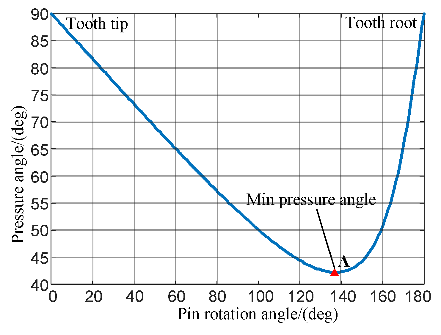
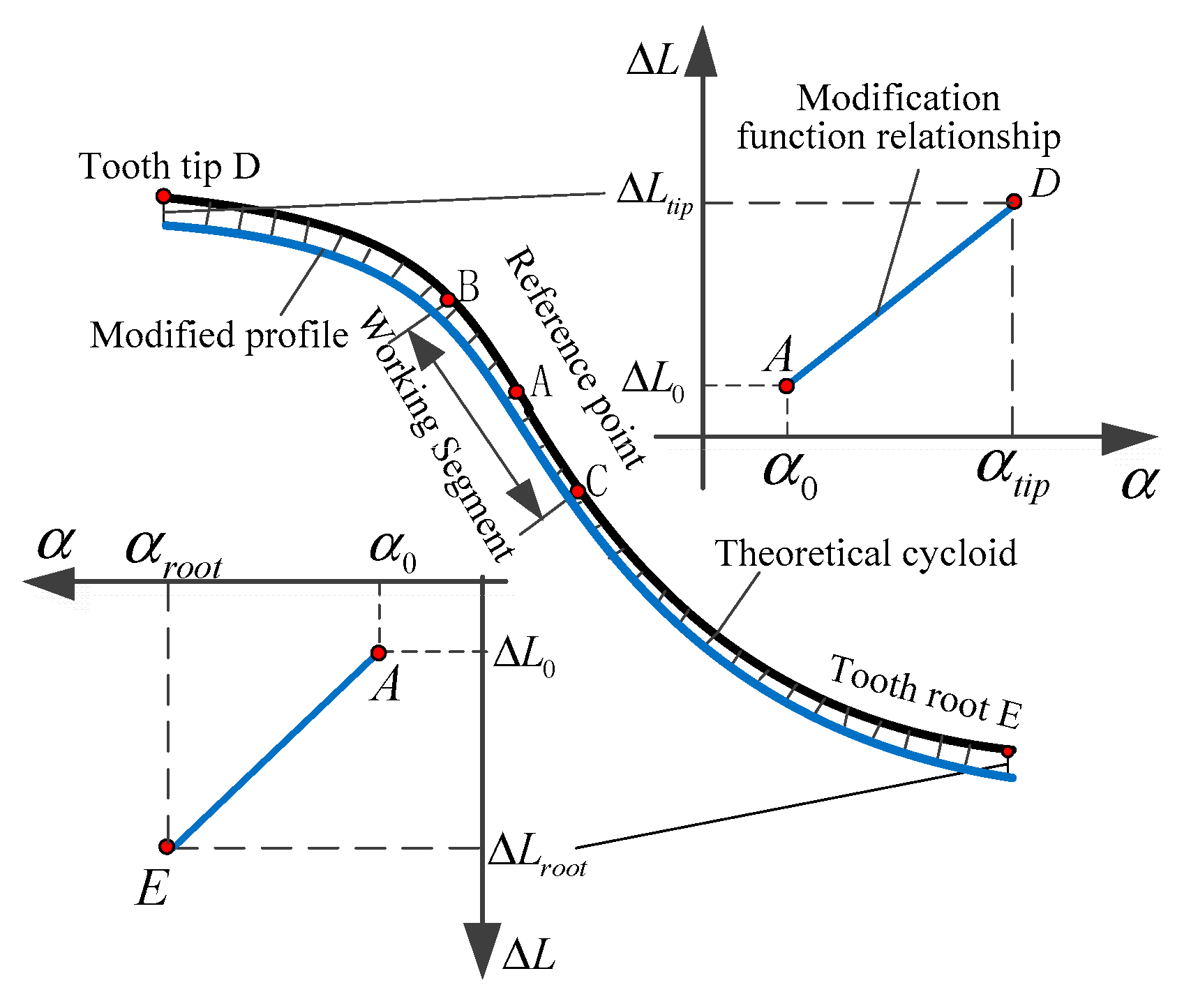
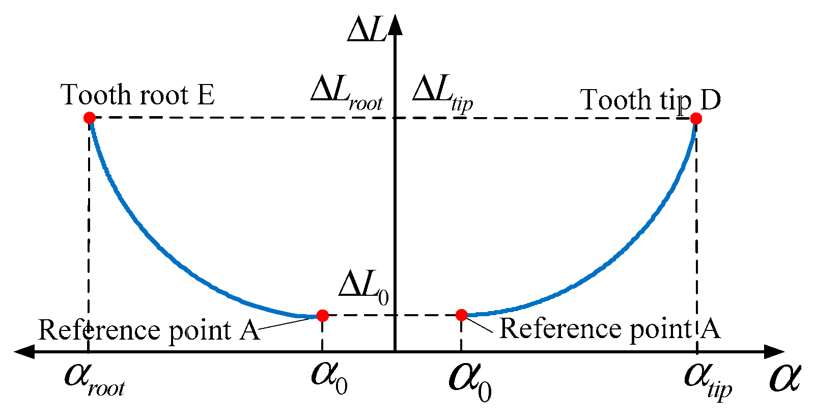
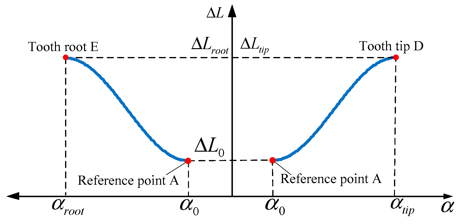
Table 1. According to the requirements of the cycloid-pin transmission, the predetermined tooth tip and root clearance are 0.02 mm and the modification value of the reference point is 0.005 mm. Through calculation, the minimum profile pressure angle is determined to be 42.24°, which is also the pressure angle at the modification reference point. Since the change trend of the modification value from the reference point A to the tooth tip D is similar to that from the reference point A to the tooth root E, only the function curve from the reference point A to the tooth tip D is plotted in Figure 11. Through substituting the pressure angle and modification value at the reference point and the tooth tip point into Equations (8) and (9), the modification curves are obtained (Figure 11).
The range of the working section of the cycloid-pin gear in the actual transmission process is relatively small. Similarly, the range of the profile pressure angle in the working section in Figure 11 is 42.24°~42.45°. In this working section, the modifications calculated by the new method are not much different, and their changes are also slow. Therefore, it can be preliminarily judged that the modified profile near the reference point A is the closest to the theoretical profile in the meshing area, and the modification effect should be reasonable.
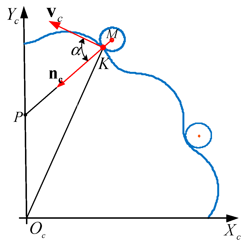
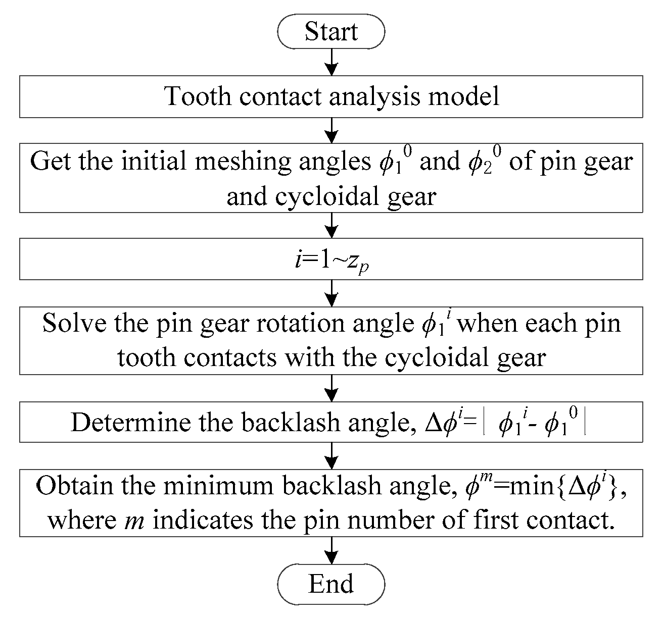
According to Equations (3) and (4), the modifications are superimposed on the normal direction of the cycloidal profile, and the modified tooth profile of the cycloid gear and pin tooth profile in coordinate system Sc are obtained. With the aid of Equation (10), the meshing contact analysis of the cycloid-pin gear after the modification is completed and the transmission error curve and the minimum backlash angle curve are obtained (Figure 12 and Figure 13). The traditional modification method adopts the modification combination of the positive equidistance and the positive displacement. The equidistant modification value is 0.005 mm and the displacement modification is 0.015 mm. These settings can ensure that the initial conditions of the traditional and new modification methods are the same for the convenience of comparison and discussion.
In Figure 12, the curve segment BiCi (i = 1, 2, 3, 4) indicates an engagement period of the modified profile and Points Bi and Ci, respectively, correspond to the meshing start and end points of the gear tooth. In the meshing area, the transmission error curves of the modified profiles are smooth and the symmetry is also good. The maximum transmission error of the traditional modification is −1.47 arcsec, which is significantly larger than that of the new method. The transmission error of the tooth profile modified by the second cycloid method is the smallest, which is −0.44 arcsec and indicates the transmission accuracy is higher.
Under the same initial clearance requirements, the minimum backlash angle curve obtained by the new modification method is basically the same and the value of the minimum backlash angle has little difference, reaching approximately 0.6 arcmin (Figure 13). The minimum backlash angle of the traditional modification method is significantly larger, reaching 0.99 arcmin. In addition, the minimum backlash angle of each modification method corresponds to the No. 31 tooth, indicating that the No. 31 tooth first comes into contact with the cycloidal profile in reverse rotation. It can be determined that the lost motions of the cycloid-pin gear after the modification by the traditional method and the proposed method are 0.6 and 0.99 arcmin, respectively.
The above results indicate that under the same initial clearance requirement, the shape of the modified tooth profile had the greater influence on the transmission error and less influence on the backlash. For the traditional modification method, although the initial clearance condition is the same as that of the proposed method, the modifications of the meshing area cannot be determined in advance, thus resulting in the larger backlash in the meshing area, which indirectly affects the repeated positioning error of the precision reducer.
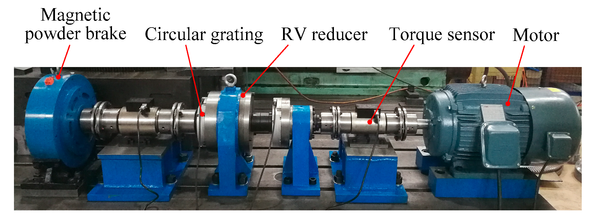
Furthermore, a measurement experiment of the transmission error and the lost motion of the robot precision reducer were carried out on a RV reducer tester shown in Figure 14. The transmission error and lost motion were measured with the static measurement method [23]. Under low-speed and no-load conditions, the high-precision circular grating installed at the input and output shafts was used to acquire the angular changes in real time.
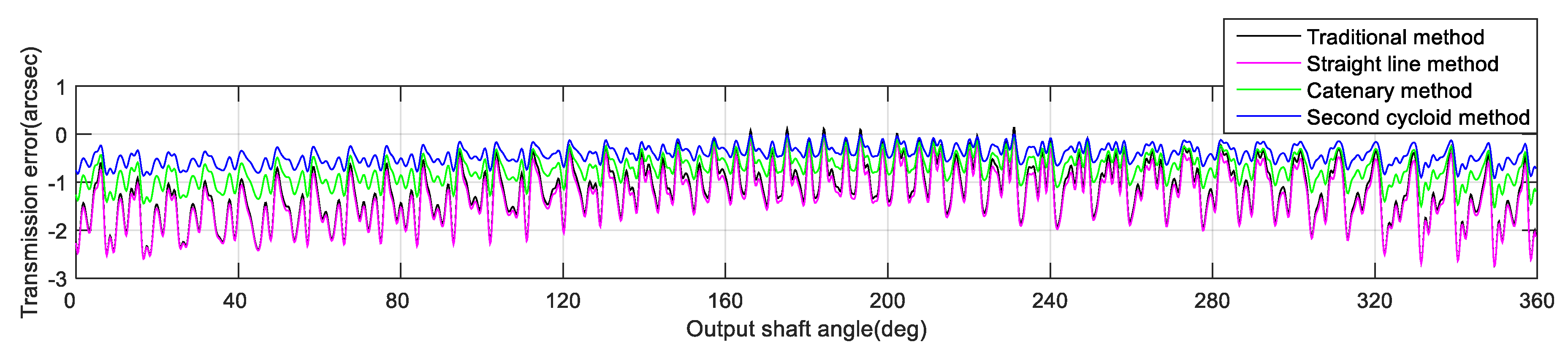
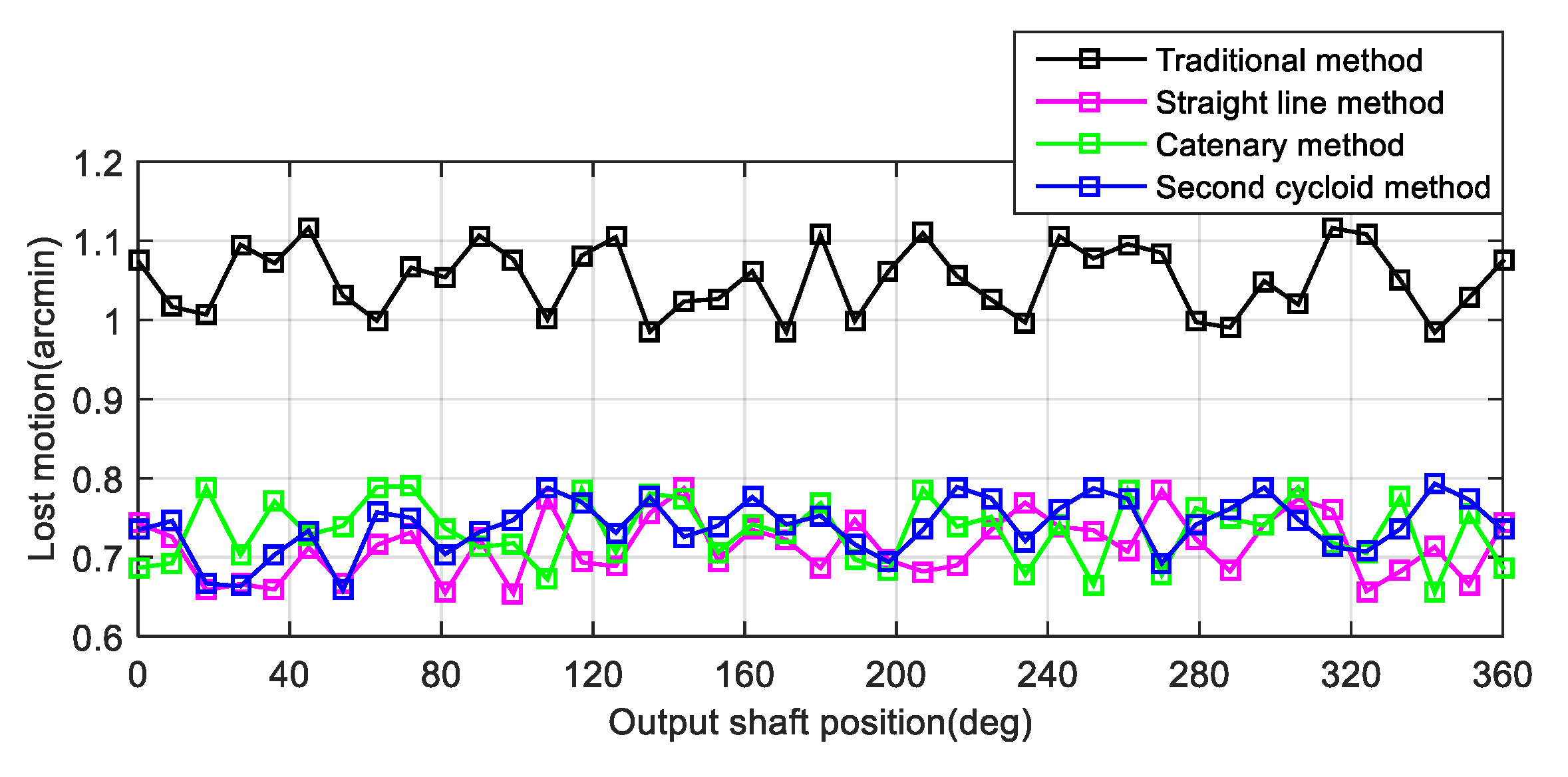
The reducer used in the measurement had 40 pins. Therefore, within the angle range (360°) of the output shaft, the rotation angle of one point was measured every 9° to obtain the actual output rotation angles at 40 positions. The cycloidal gear in this reducer was respectively replaced by the cycloidal gears modified by the traditional method, straight line method, cycloid method and catenary method. Their static transmission error curves and geometric lost motion curves were obtained (Figure 15 and Figure 16).
It can be seen from Figure 12, Figure 13, Figure 15 and Figure 16 that the error values obtained from actual measurements were greater than those obtained from theoretical modeling. The reasons might be as follows. The actual measurement process was affected by many influencing factors, such as installation errors, tooth profile errors, tooth pitch errors, and radial runout. The combined effects of these factors were complex and could not be accurately determined. However, before the test, a series of measures were taken to minimize these effects. For example, through the adjustment and detection of the tooling and precision instruments for many times, the high installation accuracy could be ensured. Through many times of precision grinding, the high processing accuracy could be ensured (the maximum profile and pitch errors of the cycloidal gear were respectively limited to 0.02 mm and 0.006 mm). However, we can see that the overall trends of transmission errors and backlashes measured in actual measurements are similar to the results of the theoretical modeling. The changing trend of the transmission error and lost motion of the new modification method is significantly smaller than that of the traditional modification. Among them, the transmission error after the second cycloid method is the least and the lost motions of the straight line method and the traditional method are basically the same.
In summary, compared with the tooth profile obtained with the traditional modification method, the modified tooth profile obtained by the proposed method can reflect smaller transmission error and backlash, indicating the higher motion accuracy and repeated positioning accuracy. Based on the working conditions and transmission requirements of robot reducers in engineering practices, the appropriate modification function can be selected to carry out the modification design of the cycloidal gear.

6. Conclusions

In this paper, the new modification design method of the tooth profile of a cycloidal gear is proposed based on the comprehensive consideration of the pressure angle distribution characteristics, the meshing backlash, the tooth tip and root clearance. In this method, the modification value is superimposed on the normal direction of the theoretical profile, the force transmission direction. According to the mathematical relationship between the modifications and the pressure angle distribution, which determines the force transmission performance, this method can flexibly control the changing trend of the cycloidal profile by using different modification piecewise functions and realize the pre-control of the transmission performance of the cycloid-pin gear. This method avoids the disadvantages of traditional modification design, such as the uncontrollable tooth profile shape and the unstable meshing accuracy after modification. The modified cycloidal-pin gear pair has good meshing contact characteristics and the better force transmission performance. The method provides a new way for the modification design of the cycloidal gear of the precision reducer of a robot.

Author Contributions

Conceptualization, T.L. and X.D.; data curation, Y.L.; formal analysis, T.L. and X.A.; funding acquisition, T.L.; methodology, T.L. and X.A.; validation, T.L. and J.L.; writing—original draft, T.L.; writing—review and editing, T.L. and X.A. All authors have read and agreed to the published version of the manuscript.

Funding

This research was funded by the National Natural Science Foundation of China (grant Nos. U1504522, 51705134 and 51775171), and key scientific research projects of higher education institutions in Henan Province of China (grant No. 20A460010).

Conflicts of Interest

The authors declare no conflict of interest.

References

  1. Pham, A.D.; Ahn, H.J. Efficiency analysis of a cycloid reducer considering tolerance. J. Frict. Wear 2017, 38, 490–496. [Google Scholar] [CrossRef]
  2. Chu, X.Y.; Xu, H.H.; Wu, X.M.; Tao, J.P.; Shao, G.F. The method of selective assembly for the RV reducer based on genetic algorithm. Proc. Inst. Mech. Eng. Part C J. Mech. Eng. Sci. 2018, 232, 921–929. [Google Scholar] [CrossRef]
  3. Litvin, F.L.; Feng, P.H. Computerized design and generation of cycloidal gearings. Mech. Mach. Theory 1996, 31, 891–911. [Google Scholar] [CrossRef]
  4. Yang, D.C.H.; Blanche, J.G. Design and application guidelines for cycloid drives with machining tolerances. Mech. Mach. Theory 1990, 25, 487–501. [Google Scholar] [CrossRef]
  5. Li, C.Y.; Chen, B.K.; Liu, J.Y. A new type of cycloid double-enveloping meshing pair. J. South China Univ. Technol. (Nat. Sci.) 2011, 39, 71–75. [Google Scholar]
  6. Sensinger, J.W. Unified approach to cycloid drive profile, stress, and efficiency optimization. J. Mech. Design 2010, 132, 0245031–0245035. [Google Scholar] [CrossRef]
  7. Ye, F.M.; Zhu, R.P.; Jin, G.H.; Bao, H.Y.; Li, F.J. Load sharing characteristics of a planetary gear train system with non-equivalent modulus and pressure angle considering backlashes. J. Vib. Shock 2015, 34, 206–211. [Google Scholar]
  8. He, W.D.; Li, L.X.; Li, X. New optimized tooth-profile of cycloidal gear of high precision RV reducer used in robot. Chin. J. Mech. Eng. 2000, 36, 51–55. [Google Scholar] [CrossRef]
  9. Ren, Z.-Y.; Mao, S.-M.; Guo, W.-C.; Guo, Z. Tooth modification and dynamic performance of the cycloidal drive. Mech. Syst. Signal Process. 2017, 85, 857–866. [Google Scholar] [CrossRef]
  10. Lin, W.S.; Shih, Y.P.; Lee, J.J. Design of a two-stage cycloidal gear reducer with tooth modifications. Mech. Mach. Theory 2014, 79, 184–197. [Google Scholar] [CrossRef]
  11. Lu, L.S.; Zhang, F.X.; Wan, Z.P.; Tang, Y. Cycloidal gear tooth profile modification of RV reducer based on backlash optimization. J. South China Univ. Technol. (Nat. Sci.) 2018, 46, 1–8. [Google Scholar]
  12. Nie, S.W.; Deng, J.; Deng, X.Z.; Geng, L.L. A flank modification method for spiral bevel gears based on mismatch topography adjustment. J. Adv. Mech. Des. Syst. 2018, 12, 1–15. [Google Scholar] [CrossRef]
  13. Demenego, A.; Vecchiato, D.; Litvin, F.L.; Nervegna, N.; Manco, S. Design and simulation of meshing of a cycloidal pump. Mech. Mach. Theory 2002, 37, 311–332. [Google Scholar] [CrossRef]
  14. Cao, X.M.; Deng, X.Z.; Wei, B.Y. A novel method for gear tooth contact analysis and experimental validation. Mech. Mach. Theory 2018, 126, 1–13. [Google Scholar] [CrossRef]
  15. Yu, H.L.; Yi, J.H.; Hu, X.; Shi, P. Study on teeth profile modification of cycloid reducer based on non-Hertz elastic contact analysis. Mech. Res. Commun. 2013, 48, 87–92. [Google Scholar] [CrossRef]
  16. Jiang, C.; Deng, X.Z.; Zhang, H.; Geng, L.L.; Nie, S.W. Prediction and simulation of cutting force in hypoid gear machining using forming method. Int. J. Adv. Manuf. Tech. 2017, 93, 2471–2483. [Google Scholar] [CrossRef]
  17. Bahk, C.J.; Parker, R.G. Analytical investigation of tooth profile modification effects on planetary gear dynamics. Mech. Mach. Theory 2013, 70, 298–319. [Google Scholar] [CrossRef]
  18. Wang, B.; Fan, M.X.; Sun, X.; Li, J.B.; Xu, A.J.; Li, G.G.; Yang, J.J. Cutter position calculation of machining equal base circle bevel gears with a pot-shaped milling cutter. Int. J. Adv. Manuf. Tech. 2016, 87, 2625–2637. [Google Scholar] [CrossRef]
  19. Li, T.X.; Li, J.B.; Deng, X.Z.; Yang, J.J.; Li, G.G.; Ma, W.S. A new digitized reverse correction method for hypoid gears based on a one-dimensional probe. Meas. Sci. Technol. 2017, 28, 125004. [Google Scholar] [CrossRef] [Green Version]
  20. Li, J.B.; Zhang, P.Z.; Feng, L.X.; Yin, G.X.; Chen, Z.; Ma, W.S.; Xu, A.J.; Nie, S.W.; Zhang, H. Information description and integration of spiral bevel gear manufacturing process under networked manufacturing mode. J. Braz. Soc. Mech. Sci. 2019, 41, 1–14. [Google Scholar] [CrossRef]
  21. Li, T.X.; Zhou, J.X.; Deng, X.Z.; Li, J.B.; Xing, C.R.; Su, J.X.; Wang, H.L. A manufacturing error measurement methodology for a rotary vector reducer cycloidal gear based on a gear measuring center. Meas. Sci. Technol. 2018, 29, 075006. [Google Scholar] [CrossRef]
  22. Yang, J.J.; Shi, Z.H.; Zhang, H.; Li, T.X.; Nie, S.W.; Wei, B.Y. Dynamic analysis of spiral bevel and hypoid gears with high-order transmission errors. J. Sound Vib. 2018, 417, 149–164. [Google Scholar] [CrossRef]
  23. Xu, H.; Shi, Z.; Yu, B.; Wang, H. Optimal Measurement Speed and Its Determination Method in the Transmission Precision Evaluation of Precision Reducers. Appl. Sci. 2019, 9, 2146. [Google Scholar] [CrossRef] [Green Version]
Figure 1. Meshing motion relationship of cycloidal-pin gear.
Applsci 10 01266 g001
Figure 2. Pressure angle of the cycloidal profile.
Applsci 10 01266 g002
Figure 3. Pressure angle distribution of the single tooth profile.
Applsci 10 01266 g003
Figure 4. Tooth profile modification strategy of a cycloidal gear.
Applsci 10 01266 g004
Figure 5. Schematic diagram of forming a cycloid.
Applsci 10 01266 g005
Figure 6. First cycloid relationship between the modification and pressure angle.
Applsci 10 01266 g006
Figure 7. Second cycloid relationship between the modification and pressure angle.
Applsci 10 01266 g007
Figure 8. Process of solving the transmission error.
Applsci 10 01266 g008
Figure 9. Backlash of cycloid-pin gear in reverse rotation.
Applsci 10 01266 g009
Figure 10. Process of solving the minimum backlash angle.
Applsci 10 01266 g010
Figure 11. Modification curves of different methods.
Applsci 10 01266 g011
Figure 12. Transmission error curves of modified tooth profiles.
Applsci 10 01266 g012
Figure 13. Minimum backlash curves of modified tooth profiles.
Applsci 10 01266 g013
Figure 14. RV reducer tester.
Applsci 10 01266 g014
Figure 15. Static transmission error curves based on actual measurements.
Applsci 10 01266 g015
Figure 16. Geometric lost motion based on actual measurements.
Applsci 10 01266 g016
Table 1. Geometric parameters of the cycloid-pin gear.
ParametersSymbolsValues
Tooth number of cycloidal gearzc39
Tooth number of pin gearzp40
Roller radiusrrp3.5 mm
Eccentricitya1.5 mm
Roller positionrp82 mm

