Article

Effect of the Lubrication Parameters on the Ceramic Ball Bearing Vibration in Starved Conditions

1
School of Mechanical Engineering, Shenyang Jianzhu University, Shenyang 110168, China
2
The State Key Laboratory of Rolling and Automation, Northeastern University, Shenyang 110819, China
*
Author to whom correspondence should be addressed.
Appl. Sci. 2020, 10(4), 1237; https://doi.org/10.3390/app10041237
Submission received: 23 December 2019 / Revised: 6 February 2020 / Accepted: 9 February 2020 / Published: 12 February 2020
(This article belongs to the Section Applied Physics General)

Abstract

:
The thickness of the oil film in ceramic ball bearings varies greatly at starved lubrication conditions, thus leading to non-uniform contact between the balls and raceways in the circumference. The lubrication parameters have a direct impact on the thickness of the oil film and then affect the dynamic characteristics of the ceramic ball bearings. A nonlinear dynamic model of ceramic ball bearing with limited lubrication is presented in this paper, and parametric studies on the effect of lubrication parameters are conducted. In starved conditions, the uneven contact between the ball and ring leads to changes in vibration, and the inner ring vibration is applied to evaluate the degree of starved lubrication. The results show that as the oil quantity increases, the bearing stiffness increases and results in increased peak frequency. As the oil quantity decreases, the thickness of the oil film reduces, resulting in the bearing vibration increase. The research findings provide a theoretical reference for ceramic ball bearing design and have guided significance for improving the service performance of ceramic ball bearings.

1. Introduction

Ceramic ball bearings have excellent performance and perform well in high temperature and high-speed environments, which can ensure the normal operation of high-speed devices [1,2]. Bearings are important to support components for equipment. The vibration characteristics of ceramic ball bearings directly affect the accuracy and vibration characteristics of the equipment.
The mechanism of bearing vibration is very complex, involving many factors, such as process errors, structural parameters, and operating parameters [3,4,5,6,7,8,9]. Zhang et al. [10] established a dynamic model to analyze the influence of structural parameters on bearing vibration. Cui et al. [11] used the theory of rolling bearing dynamics to establish a dynamic analysis model of angular contact ball bearings. It is found that adjusting the structural parameters and the axial preload can reduce the vibration of the bearing. Bai et al. [12] developed a nonlinear dynamic model of full ceramic bearings, considering different diameters of the ball, oil film forces, and load. The dynamic response of each element of the full ceramic bearing is obtained by solving the model.
Bearing vibration is not just related to structural parameters, but is also affected by the working parameters, including lubrication [13,14,15]. The lubricating oil cannot enter the bearing smoothly under high-speed, heavy-duty conditions. The amount of oil inside the bearing gradually decreases and the starvation state occurs [16,17,18,19,20,21,22]. This phenomenon has attracted a lot of research interest in the field of starvation lubrication. Tanaka [23] studied the hydrodynamic performance of journal bearings in the absence of lubrication from theoretical and experimental conditions. The reduction in film thickness along the bearing circumference can affect the static and dynamic performance of journal bearings. Maruyama and Saitoh [24] studied the relationship between oil supply flow and oil film thickness under stable starvation lubrication conditions. The flow rate of the supplied oil was precisely controlled in the experiment and the oil film thickness was measured. The relationship between the oil supply flow rate and the oil film thickness is determined. Ebner et al. [25] studied the effects of insufficient lubrication on the working behavior of elastohydrodynamic lubrication (EHL) contactors in gears. The results show that a small amount of initial oil can lubricate normally and have different operating performance on different surfaces. Results show that a very small amount of initial oil is sufficient for lubrication and different operating behaviors for different surfaces. Hamrock and Dowson [26,27] simulated the starvation phenomenon by moving the entrance to the contact center and calculated the actual distance of the entrance by the correction factor of the oil film thickness. Wedeven et al. [28] studied the effect of lubricant distribution on oil film thickness in the inlet area of EHL. The minimum meniscus length of the EHL inlet area is theoretically determined to prevent insufficient lubrication. Liu et al. [29] studied the sliding contact situation under various lubricant quantities. Theoretical results show that the starved film has a certain carrying capacity and the film thickness is a sensitive function of the amount of lubricant supplied. Venner et al. [30] proposed a model for predicting the change in the grease layer in a rolling bearing because of the centrifugal force of the ball and the EHL contact pressure. This model estimates the longest local replenishment interval to ensure the normal bearing operation and helps to improve bearing life predictions related to lubricants.
However, the currently developed models are based primarily on the theory of EHL to analyze the effect of the amount of lubricant on the operation of the mechanism. There are few studies on the impact of the amount of lubricant on the dynamic performance of bearings in dynamic models. Recently, Bai et al. [31] showed that uneven contact between the ball and ring would affect the vibration conditions of the entire ceramic bearing. In the starving lubrication, uneven contact becomes more apparent. Under starvation lubrication conditions, the thickness of the lubricant film that transfers the load between the ball and the raceway is very thin and unstable. Different oil film thickness will lead to different bearing load conditions and then affect the dynamic characteristics of the bearing. In this paper, a nonlinear dynamic model of ceramic ball bearings with starved lubrication is established. Considering detailed lubrication conditions with lubrication parameters, through numerical calculations, the influence of the oil amount on the vibration of the bearing inner ring was studied.

2. Dynamic Model

2.1. Contact Model between the Balls and Inner Ring

Model of the Inner Ring

In order to facilitate the analysis of the dynamic performance of ceramic ball bearings, the following assumptions were made: The working surface of the bearing parts has an ideal geometry and the center of mass coincides with the centroid; the outer ring of the bearing does not rotate and the inner ring rotates around the X-axis; each ball has the same diameter; the inertial coordinate system of the bearing is {O; X, Y, Z}; the inner ring coordinate system of the bearing is {O; Xi, Yi, Zi}; and the coordinate system of the jth ball is {Obj; Xbj, Ybj, Zbj}. When an angular contact ball bearing rotated at high speed, the inner ring was subjected to the normal contact force of the ball, the traction force, the friction of the lubricating oil, and the applied load. The force model of the inner ring is shown in Figure 1.
The inner ring dynamic nonlinear differential equations can be expressed as:
F x + j = 1 z ( F R η i j cos α i j - Q i j sin α i j ) = m i x ¨ i
F y + j = 1 z [ ( F R η i j sin α i j - Q i j cos α i j ) cos φ j + ( T ξ i j - F R ξ i j ) sin φ j ] = m i y ¨ i
F z + j = 1 z [ ( F R η i j sin α i j + Q i j cos α i j ) sin φ j - ( T ξ i j - F R ξ i j ) cos φ j ] = m i z i
M y + j = 1 z [ r i j ( - F R η i j cos α i j + Q i j sin α i j ) sin φ j + D 2 r i j T ξ i j sin α i j cos φ j ] = I i y ω . i y - ( I i z - I i x ) ω i z ω i x
M z + j = 1 z [ r i j ( - F R η i j cos α i j + Q i j sin α i j ) cos φ j + D 2 r i j T ξ i j sin α i j sin φ j ] = I i z ω . i z - ( I i x - I i y ) ω i y ω i x
where the contact surface between the ball and the raceway is approximately an ellipse, η and ξ are the short axis and the long axis of the contact ellipse between the ball and the raceway, subscript i represents the inner ring, Fx, Fy, Fz, My, and Mz are externally applied forces and torques, αij is the contact angle between the ball and inner raceway, φ i j is the azimuth of the jth ball, Qij is normal contact force between the ball and inner raceway, Tηij is the traction force of the contact surfaces, FRηij is a hydrodynamic frictional force at the inlet zone, mi is the mass of the inner ring, x ¨ i ,   y ¨ i ,   and   z ¨ i , are the acceleration of the inner ring in the inertial coordinate system, Iix, Iiy, and Iiz are the principal moments of inertia of the inner ring in the inertial coordinate system, ω i x ,   ω i y ,   and   ω i z represent the angular velocity of the inner ring in the inertial coordinate system, ω . iy   and   ω . iz are the angular accelerations of the inner ring in the inertial coordinate system, D is the normal ball diameter, and rij is the rolling radius:
r i j = 0.5 d - R i cos α i j
where d is the pitch diameter of the bearing and Ri is groove curvature radius of the inner race raceway.

2.2. Model of the Ball at Normal Lubricated Conditions

When fully lubricated, the oil filled the gap between the ball and the inner ring to allow the ball to be loaded. The force acting on the loaded ball is shown in Figure 2.
The dynamic differential equations of the fully lubricated ball are shown as:
Q i j sin α i j - Q e j sin α e j + T η i j cos α i j - T η e j cos α e j - F R η i j cos α i j + F R η e j cos α e j + P S ξ j + P R ξ j = m b x ¨ b j
Q i j cos α i j - Q e j cos α e j - T η i j sin α i j + T η e j sin α e j + F R η i j sin α i j - F R η e j sin α e j + F η j - P S η j - P R η j = m b y ¨ b j
T ξ e j - T ξ i j - F R ξ e j + F R ξ i j + Q c j - F D j - F τ j = m b z ¨ b j
( T ξ e j - F R ξ e j ) D 2 cos α e j + ( T ξ i j - F R ξ i j ) D 2 cos α i j - ( P S η j + P R η j ) D 2 - J x ω . x j = I b ω . b j x
( F R ξ e j - T ξ e j ) D 2 sin α e j + ( F R ξ i j - T ξ i j ) D 2 sin α i j - G y j - ( P S ξ j + P R ξ j ) D 2 - J y ω . y j = I b ω . b j y - I b ω b j z θ . b j
( T η i j - F R η i j ) D 2 + ( T η e j - F R η e j ) D 2 cos α i j - G z j - J z ω . z j = I b ω . b j z - I b ω b j y θ . b j
where subscript e represents the outer ring, αij, and αej are the contact angles between the ball and raceway, Qij, and Qej are the normal contact forces between the ball and raceway, Tηij, Tηej, Tξij, and Tξej are traction forces of the contact surfaces, Qcj is the collision force between the jth ball and the cage, Fηj and Fτj are components of the ball’s center, Pj and Pj are the rolling frictional forces acting on the ball’s surfacem Pj and Pj are the sliding frictional forces acting on the ball’s surface, FRηij, FRηej, FRξij and FRξej are the hydrodynamic frictional forces at the inlet zone, Jx, Jy and Jz are components of the ball’s moment of inertia of xbj, ybj, and zbj directions, Gyj and Gzj are components of the ball’s inertia moment of ybj and zbj directions, FDj is the aerodynamic resistance acting on the ball by the gas–oil mixture, ωxj, ωyj and ωzj are the angular velocity of the jth ball in {Obj; Xbj, Ybj, Zbj}, and ω . x j ,   ω . y j ,   ω . z j are the angular accelerations of the jth ball in {Obj; Xbj, Ybj, Zbj}. mb is the mass of the ball x ¨ b j ,   y ¨ b j ,   and   z ¨ b j are the displacement accelerations of the jth ball in the inertial coordinate system, Ibj is moments of inertia of the jth ball, ωbjx, ωbjy, and ωbjz are the angular velocities of the jth ball in the inertial coordinate system, ω . b j x ,   ω . b j y ,   and   ω . b j z are the angular accelerations of the jth ball in the inertial coordinate system, and θ . b j is orbit speed of the jth ball in the inertial coordinate system.

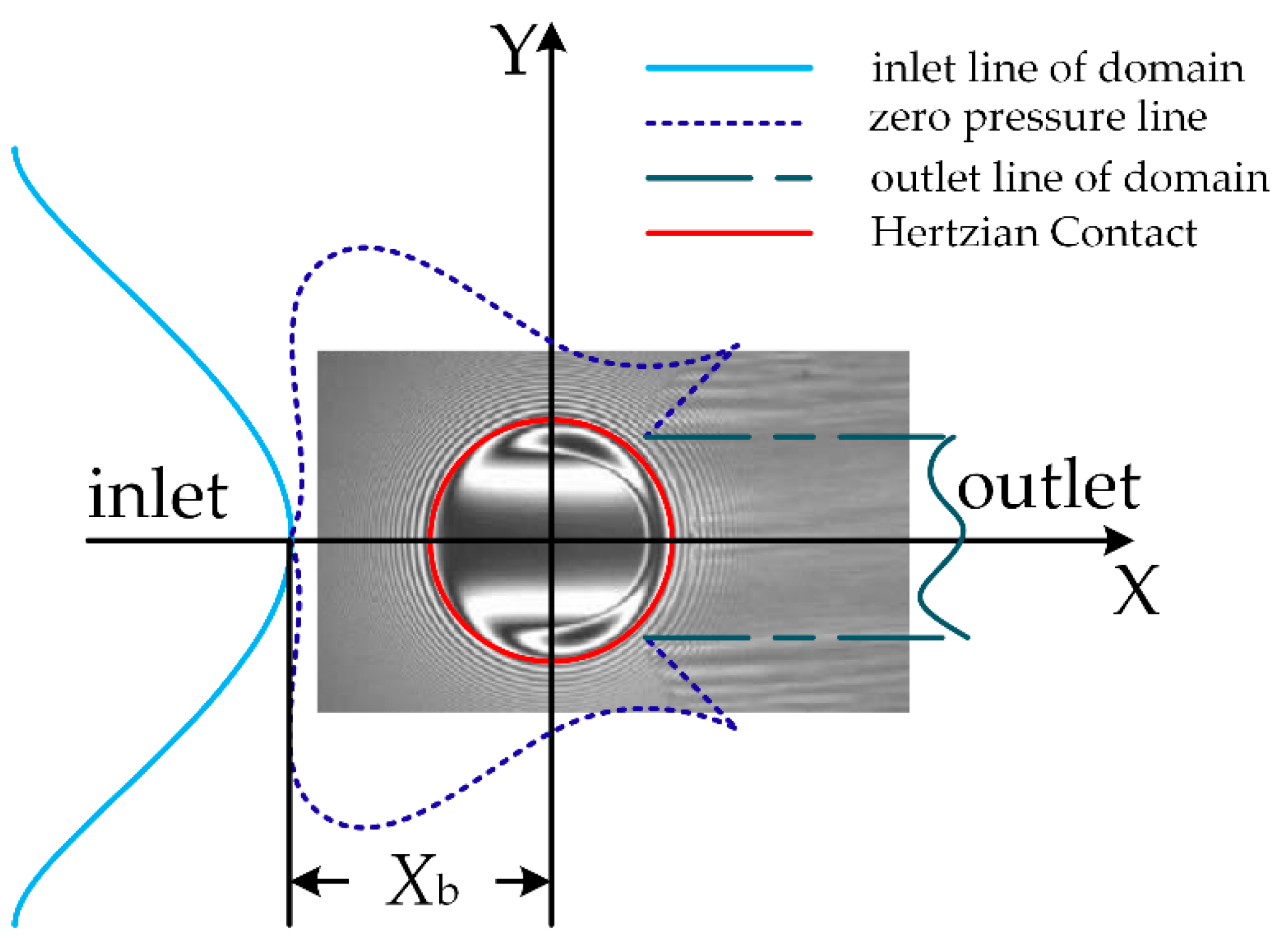
2.3. Model of the Ball at Starved Lubricated Conditions

The lubrication regime in bearings was governed by EHL. In this application, when the amount of lubricant was enough to fill the inlet of the contact, the lubrication method was called full filling. However, in the process of bearing a high-speed operation, the oil could not be replenished quickly enough after the ball rolling. At this point, the lubricant supply at the inlet was insufficient and entered the stage of oil starvation.
When there was enough oil, the central oil film thickness hc was generally a function of viscosity, load, contact material, and shape, regardless of temperature, and can be expressed as:
h c = f ( α 0 , η 0 , u , R , Q , E )
where α0 is the pressure index of viscosity, η0 is the dynamic viscosity at normal pressure, R is the equivalent radius of curvature, Q is the normal contact force between the ball and raceway, and u is the average surface velocity and can be expressed as:
u = d 2 - D 2 4 d ω
where ω is the angular velocity of the inner ring and E is the equivalent elastic modulus and satisfies the following equation:
1 E = 0.5 [ 1 ν 1 2 E 1 + 1 ν 2 2 E 2 ]
where E1 and E2 are elastic moduli of the two contact materials and v1 and v2 are Poisson’s ratios of the two contact materials.
In order to facilitate analysis, these parameters were dimensionless, as follows:
H c = φ ( U , W , G )
where Hc is a dimensionless central film thickness:
H c = h c R x
where Rx is the equivalent radius of curvature in the long axis direction.
The velocity parameter U is expressed as
U = η 0 u E R x ,
the load parameter W is expressed as
W = Q E R x ,
and the material parameter G is expressed as
G = α 0 E .
Using these dimensionless parameters, Hamrock and Dowson [26] proposed a formula for calculating the numerical solution of point contact dimensionless elastohydrodynamic lubricating film thickness and dimensionless minimum film thickness:
H c = 2.69 U 0.67 W - 0.067 G 0.53 ( 1 - 0.61 e - 0.72 k )
H min = 3.63 U 0.68 W - 0.073 G 0.49 ( 1 - e - 0.68 k )
where k is the ellipticity and can be expressed as:
k = a b 1.03391 ( R y R x ) 0.636
where a is the long half axis of the ellipse, b is the short half axis of the ellipse, and Ry is the equivalent radius of curvature in the short axis direction.
Therefore, the corresponding central oil film thickness and minimum film thickness are shown as:
h c = H c R x = 2.69 α 0 0.53 ( η 0 u ) 0.67 R x 0.464 Q - 0.067 E - 0.073 ( 1 - 0.61 e - 0.72 k )
h min = H min R x = 3.63 α 0 0.49 ( η 0 u ) 0.68 R x 0.466 Q - 0.073 E - 0.017 ( 1 - e - 0.68 k )
where e is the constant of nature.
Hamrock and Dowson [26] simulated starvation by moving the inlet to the contact center and proposed a correction coefficient to show the change of oil film thickness with the inlet distance. They calculated the minimum length of the film inlet area to ensure adequate lubrication. Mohammadpour [32] obtained a photo–micrograph of the interferogram of the lubricant film under the same conditions as the isobaric curve, as shown in Figure 3. The actual distance Xb between the inlet and the Hertz contact center is marked in Figure 3.
Xb can be expressed as:
X b = b + ( h b / h c - 1 1.21 ) 2 3 ( R h c ) 2 3 b - 1 3
where hb is the oil film thickness at the lubrication inlet:
h b = ( 3 Q v τ 2 π ω 2 r 2 ) 2 3
where Qv is the supplied oil flow rate, τ is the kinematic viscosity of the lubricating oil and ω is the angular velocity of the inner ring, and r is the inner ring radius.
Let L be a dimensionless parameter of Xb, so the dimensionless distance L is determined by
L = ( X b b )
The boundary between fully flooded and starved (L*) can be expressed as:
L * = 1 + 3.06 [ ( R x b ) 2 H c ] 0.56
where Hc is dimensionless hc (Hc = hc/Rx). Thus, the starvation condition can be determined by the boundary condition on L. When L > L*, the lubricating oil completely flooded the inlet zone, and when L < L*, the oil film thickness decreased and the bearing entered a starvation state. The actual central oil film thickness, hc1, can be obtained as:
h c 1 = ( L - 1 L * - 1 ) 0.25 h c
when fully lubricated, the thickness of the lubricant was sufficient to carry the load. When the oil decreased gradually, it was not enough to fill the gap, so the ball could not contact the inner race. At this time, the differential equations of the ball in the starvation lubrication state are shown as:
- Q e j sin α e j - T η e j cos α e j + F R η e j cos α e j + P S ξ j + P R ξ j = m b x ¨ b j
Q e j cos α e j + T η e j sin α e j - F R η e j sin α e j + F η j - P S η j - P R η j = m b y ¨ b j
T ξ e j - F R ξ e j + Q c j - F D j - F τ j = m b z ¨ b j
( T ξ e j - F R ξ e j ) D 2 cos α e j - ( P S η j + P R η j ) D 2 - J x ω . x j = I b ω . b j x
( F R ξ e j - T ξ e j ) D 2 sin α e j - G y j - ( P S ξ j + P R ξ j ) D 2 - J y ω . y j = I b ω . b j y - I b ω b j z θ . b j
( T η e j - F R η e j ) D 2 cos α i j - G z j - J z ω . z j = I b ω . b j z - I b ω b j y θ . b j

3. Numerical Simulation

The main parameters of the bearing used in the calculation are shown in Table 1.
The balls are marked 1–18 sequentially, as shown in Figure 4.
The values of L, L* can be obtained by calculating Equations (1)–(28), and the relationship between Qv and L is obtained, as shown in Figure 5.
The red line shown in Figure 5 is the calculated dimensionless inlet distance at the boundary between fully flooded and starved (L*), and L decreased with the decrease of Qv. When L < L*, it was the starved state.
In order to obtain the detailed variation of vibration, L = 1.1, 1.3, 1.5, 1.7, and 1.9 were selected to represent the amount of lubricant for analysis, and the bearing vibration conditions, in which different dimensionless inlet distances L are different, were studied. When the lubricating oil was sufficient with L = 1.9, the bearing vibration could be obtained from Equations (1)–(30). When the bearing ran in the starved conditions with L = 1.1 to 1.7, the vibration of the bearing could be obtained from Equations (1)–(6) and (13)–(36). The difference in the dynamic response under certain radial loads under different lubrication conditions is shown in Figure 6, Figure 7, Figure 8, Figure 9 and Figure 10. Assuming the rotation speed of the inner ring is 15,000 r/min, the radial force (Fz) was 10 N, 20 N, and 30 N, respectively.
With the increase in oil content, the friction coefficient between the ball and inner ring decreased gradually, and the contact load distribution became uniform. These changes caused the vibration of the bearing inner ring to decrease slightly. In Figure 6, when the dimensionless inlet distance was small (L = 1.1), the bearing vibration amplitude could reach 32 mm/s. In Figure 7, the dimensionless inlet distance was set to 1.3 and the bearing vibration amplitude was 24 mm/s, which was lower than Figure 6. In Figure 8, Figure 9 and Figure 10, the maximum amplitudes were 19, 20, and 16. This shows that the amplitude of bearing vibration decreased slightly with the increase of oil amount. By comparison, the vibration amplitude of the bearing in Figure 6 was significantly smaller than that in Figure 10, which verifies the analysis results. As the oil amount increased, the trend of vibration amplitude decreased. This shows that the applied load had a greater influence on the bearing of starved lubrication conditions. Furthermore, it can be seen in Figure 6 and Figure 10 that the natural frequency of the bearing was considerably increased. This is explained by the fact that the natural frequency of the bearing is related to the stiffness. The oil film stiffness Koil between the ball and the raceway is expressed as:
K o i l = d Q d h min = 6.4066 × 10 8 h min - 14.6986 U 9.31507 G 6.7123 R x 15.6986 E ( 1 - e - 0.68 k ) 13.6986
The contact stiffness Kc between the ball and the raceway is expressed as:
K c = d Q d δ = 1.5 ( K 2 Q ) 1 / 3
where K is the contact coefficient between the ball and the raceway. Krij refers to the radial component of the comprehensive stiffness between the ball and the inner ring, and Kaij refers to the axial component of the comprehensive stiffness between the ball and the inner ring.
K ri j = ( K o i l ) i j × ( K c ) i j ( K o i l ) i j + ( K c ) i j × cos 2 α i j
K ai j = ( K o i l ) i j × ( K c ) i j ( K o i l ) i j + ( K c ) i j × sin 2 α i j
K ae j = ( K o i l ) e j × ( K c ) e j ( K o i l ) e j + ( K c ) e j × sin 2 α e j
K re j = ( K o i l ) e j × ( K c ) e j ( K o i l ) e j + ( K c ) e j × cos 2 α e j
where (Koil)ij is the oil film stiffness of the jth ball and the inner ring and (Kc)ij is the contact stiffness between the jth ball and the inner ring. Bearing axial stiffness Ka and radial stiffness Kr can be expressed as:
K a = j = 1 Z K a i j K a e j K a i j + K a e j
K r = j = 1 Z K ri j K r e j K r i j + K r e j cos 2 ( 2 π / Z ( j - 1 ) )
The natural frequency of the bearing vibration can be expressed as:
f x = ( 0.5 π ) K a / M
f y = ( 0.5 π ) K r / M
where M is the mass of the bearing system.
When the thickness of the oil film was small, for example, L = 1.1, some balls could nor contact the raceway, and the contact stiffness Kc was 0. According to Equations (39)–(42), this shows that Krij, Kaij, Krej, and Kaej were also 0. Therefore, by calculating Equations (43) and (44), we can get the total stiffness. When the thickness of the oil film was large, for example, L = 1.9, all the balls could contact the raceway. By calculating (41) and (42), this shows that the stiffness at this time was greater than the stiffness at L = 1.1. According to Equations (45) and (46) that the greater the stiffness, the greater the natural frequency of the bearing. This phenomenon can be seen in Figure 6, Figure 7, Figure 8, Figure 9 and Figure 10. It can also be seen from Figure 6, Figure 7, Figure 8, Figure 9 and Figure 10 that the bearing vibration natural frequency increased with radial load. As a result, the increase in load increased the contact force between the ball and the raceway. As a result, the minimum oil film thickness was reduced, and the oil film stiffness increased.
Assuming the rotation speed of the inner ring was 15,000 r/min, the axial force (Fx) was 10 N, 20 N, and 30 N, respectively, and the radial force (Fz) was 0 N. Figure 11, Figure 12, Figure 13, Figure 14 and Figure 15 show the relationship between the axial load of the bearing and the vibration of the bearing when the dimensionless inlet distance L was different.
It can be observed from Figure 11, Figure 12, Figure 13, Figure 14 and Figure 15 that as the amount of oil increased, the amplitude of bearing vibration significantly reduced. The dominant frequency of the bearing increased as the oil quantity increased. These characteristics were the same as the changes in Figure 6, Figure 7, Figure 8, Figure 9 and Figure 10. As shown, during the increase, the bearing vibration decreased with a certain amount of force. According to Equation (1), the force generated in the bearing could be balanced when by applying a certain axial load, and the vibration of the bearing reduced. When the load continued to increase, it increased the bearing vibration. Therefore, for bearings with a given structure, there was a reasonable range of axial loads that made the bearings vibrate less during operation.
Figure 16 and Figure 17 show the relationship between the inlet distance and the peak vibration frequency fp of the bearing under different working conditions.
As the oil increased, the contact stiffness of the ball with the inner ring increased, resulting in an increase in the natural frequency of the bearing. When the amount of oil increased and L > L*, the oil film thickness did not change substantially, and the influence of the increase of the oil quantity on the rigidity became small. Therefore, the natural frequency of the bearing did not change any more, as shown in Figure 16 and Figure 17.
Figure 18 and Figure 19 show the relationship between the inlet distance and the amplitude of axial and radial vibration velocity of bearing vibration under different working conditions.
When the oil film thickness was very small, the ball and the inner ring could be regarded to be in direct contact. The contact surface friction was enhanced, causing the bearing to generate a large amplitude of vibration. As the amount of lubricating oil increased, the oil film separated the ball from the raceway. The contact surface friction was reduced, the contact load distribution was uniform, and the amplitude of the bearing vibration gradually decreased. In Figure 18 and Figure 19, it can be obviously observed that as L increased, the vibration amplitude of the bearing greatly reduced. When the oil quantity increased to L > L*, there was no substantial change in oil film thickness. At this time, the influence of the increase of oil amount on the friction of the contact surface became small. Therefore, the vibration amplitude of the bearing no longer changed.

4. Discussion

By considering the lubrication in the differential equation of bearing dynamics, the influence of the amount of lubricant on the dynamic characteristics of the bearing can be obtained, as well as the degree of influence of the amount of lubricant on the vibration of the bearing inner ring under different external loads. This paper is based on the critical inlet distance L* defined by Hamrock [26] to determine whether the bearing is starved. According to Figure 16, Figure 17, Figure 18 and Figure 19 the lines trend changed at the boundary between fully flooded and starved conditions. This indicates that the bearing vibration changed under starvation and full flooding. In the absence of oil, factors such as uneven contact between the ball and the inner ring can have a greater impact on bearing vibration. The degree of changing in bearing vibration with load was also more pronounced. The contact force and friction between the inner ring and the ball increased because of starved lubrication. The contact force between the ball and the inner ring was stronger, and the vibration of the inner ring increased. Lubrication increased the contact stiffness of the contact pairs in the bearing, and the natural frequency of the bearing vibration also increased. In the case of a sufficient amount of oil, the thickness of the oil film substantially unchanged. The contact load between the ball and the inner ring was evenly distributed, and the frictional force decreased to gradually reduce the bearing vibration and reach a steady state. The contact stiffness of the contact pair in the bearing tended to be stable, so the inherent frequency of the bearing vibration did not change.

5. Conclusions

This paper proposes a bearing dynamic model that considers the change of the lubrication parameters and conducts investigations on the bearing vibration based on the models. The results show that the vibration conditions of the bearing under the starved lubricated conditions are different from those with enough oil. In the case of oil starvation, factors such as non-uniform contact between the ball and inner ring have a greater impact on bearing vibration. The bearing vibration decreases as the oil flow increases, and the bearing vibration can be minimized when the amount of lubricant is just enough to prevent a substantial reduction in the minimum film thickness. Furthermore, the peak frequencies also increase with the oil flow, and the growth flattens as the oil continues to increase towards fully flooded. This study obtained the impact of lubricant supply on bearing vibration and provided theoretical foundations to the application of full ceramic bearings.

Author Contributions

Conceptualization, K.Z. and X.B.; formal analysis, K.Z. and X.W.; funding acquisition, K.Z. and X.B.; investigation, X.W.; methodology, Z.W. and X.B.; resources, K.Z. and D.Z.; supervision, K.Z. and X.B.; validation, J.S. and D.Z.; visualization, X.W.; writing—original draft, X.W.; writing—review and editing, K.Z. and X.B. All authors have read and agreed to the published version of the manuscript.

Funding

This research was funded by the National Key R&D Program of China [grant number 2017YFC0703903], National Natural Science Foundations of China [grant number 51675353, 51905357] and Scientific Research Project of Liaoning Provincial Department of Education [grant number lnqn201909].

Acknowledgments

This work got support from the researchers in the laboratory of ceramic motorized spindle of Shenyang Jianzhu University and the funders. The authors are thankful for their help during the research.

Conflicts of Interest

The authors declare no conflict of interest.

Nomenclature

aThe long half axis of the ellipse
bThe short half axis of the ellipse
DThe normal ball diameter
dThe pitch diameter of the bearing
eThe constant of nature
EEquivalent elastic modulus
E1, E2Elastic moduli of the two contact materials
Fx, Fy, FzComponents externally applied forces of X, Y, and Z directions
FRηij, FRηej, FRξij, FRξejHydrodynamic frictional forces at the inlet zone
Fηj, FτjInertial force component of the ball
FDjAerodynamic resistance acting on the ball by the gas–oil mixture;
fx, fyThe natural frequency of bearing vibration in axial and radial directions
GMaterial parameter
Gyj, GzjComponents of the ball’s inertia moment of ybj and zbj directions
hbThe oil film thickness at the lubrication inlet
HcA dimensionless central oil film thickness
hcThe central oil film thickness
hminThe minimum oil film thickness
hc1The actual central oil film thickness
IbjMoments of inertia of the jth ball
Iix, Iiy, IizThe principal moments of inertia of the inner ring in the inertial coordinate system
Jx, Jy, JzComponents of the ball’s moment of inertia of xbj, ybj, and zbj directions
jThe jth ball
KoilThe oil film stiffness between the ball and the raceway
KcThe contact stiffness
KThe contact coefficient between the ball and the raceway
KrijThe radial component of the comprehensive stiffness between the jth ball and the inner ring
KaijThe axial component of the comprehensive stiffness between the jth ball and the inner ring
KaejThe axial component of the comprehensive stiffness between the jth ball and the outer ring
KrejThe radial component of the comprehensive stiffness between the jth ball and the outer ring
(Koil)ijThe oil film stiffness of the jth ball and the inner ring
(Koil)ejThe oil film stiffness of the jth ball and the outer ring
(Kc)ijThe contact stiffness between the jth ball and the inner ring
(Kc)ejThe contact stiffness between the jth ball and the outer ring
KaAxial stiffness
KrRadial stiffness
kEllipticity
LThe dimensionless distance between the inlet and the Hertz contact center
L*The boundary between fully flooded and starved
My, MzExternally applied torques
miMass of the inner ring
mbMass of the ball
MMass of the bearing system
{O; X, Y, Z}The inertial coordinate system of the bearing
{O; Xi, Yi, Zi}The inner ring coordinate system of the bearing
{Obj; Xbj, Ybj, Zbj}The coordinate system of the jth ball
PRηj, PRξjRolling frictional forces acting on the ball’s surface
PSηj, PSξjSliding frictional forces acting on the ball’s surface
Qij, QejNormal contact forces between the ball and raceway
QcjCollision force between the jth ball and the cage
QvThe supplied oil flow rate
QNormal contact force between the ball and raceway
rijThe rolling radius
RiGroove curvature radius of inner race raceway
RThe equivalent radius of curvature
RxThe equivalent radius of curvature in the long axis direction
RyThe equivalent radius of curvature in the short axis direction
rThe inner ring radius
Tηij, Tηej, Tξij, TξejTraction forces of the contact surfaces
uThe average surface velocity
UVelocity parameter
v1 and v2Poisson’s ratios of the two contact materials
WLoad parameter
x ¨ i ,   y ¨ i ,   z ¨ i , The acceleration of the inner ring in the inertial coordinate system
x ¨ b j ,   y ¨ b j ,   z ¨ b j Displacement accelerations of the jth ball in the inertial coordinate system
XbThe actual distance between the inlet and the Hertz contact center
αij, αejContact angles between the ball and raceway
α0The pressure index of viscosity
δThe contact deformation between the ball and the inner ring
ηThe short axis of the ellipse
η0The dynamic viscosity at normal pressure
τThe kinematic viscosity of the lubricating oil
φ i j The azimuth of the jth ball
ξThe long axis of the ellipse
θ . b j Orbit speed of the jth ball in the inertial coordinate system
ωThe angular velocity of the inner ring
ω i x , ω i y , ω i z Represent the angular velocity of the inner ring in the inertial coordinate system
ω . i y ,   ω . i z The angular accelerations of the inner ring in the inertial coordinate system
ωxj, ωyj, ωzjThe angular velocity of the jth ball in {Obj; Xbj, Ybj, Zbj}
ω . x j ,   ω . y j ,   ω . z j The angular accelerations of the jth ball in {Obj; Xbj, Ybj, Zbj}
ωbjx, ωbjy, ωbjzThe angular velocities of the jth ball in the inertial coordinate system
ω . b j x ,   ω . b j y ,   ω . b j z The angular accelerations of the jth ball in the inertial coordinate system
Subscript iRepresents the inner ring
Subscript eRepresents the outer ring

References

  1. Wu, Y.H.; Zhang, L.X.; Zhang, K.; Li, S.H. Design on High-Speed Precision Grinder. Key Eng. Mater. 2006, 304, 492–496. [Google Scholar] [CrossRef]
  2. Li, S.H.; Wu, Y.H.; Zhang, K. Parameter Optimization for Oil/Air Lubrication of High Speed Ceramic Motorized Spindle without Bearing Inner Rings. Appl. Mech. Mater. 2010, 37, 839–843. [Google Scholar] [CrossRef]
  3. Tiwari, M.; Gupta, K.; Prakash, O. Dynamic response of an unbalanced rotor supported on ball bearings. J. Sound Vib. 2000, 238, 757–779. [Google Scholar] [CrossRef]
  4. Harsha, S.P. Nonlinear dynamic response of a balanced rotor supported by rolling element bearings due to radial internal clearance effect. Mech. Mach. Theory 2006, 41, 688–706. [Google Scholar] [CrossRef]
  5. Tripathi, J.S.; Agrawal, J.F. Development of Analytical Model of Ball Bearings for EHL Contact. IJRMEE 2018, 5, 5–12. [Google Scholar]
  6. Shi, H.T.; Bai, X.T. Model-based uneven loading condition monitoring of full ceramic ball bearings in starved lubrication. Mech. Syst. Signal Pr. 2020, 139, 106583. [Google Scholar] [CrossRef]
  7. Nonato, F.; Cavalca, K.L. An approach for including the stiffness and damping of elastohydrodynamic point contacts in deep groove ball bearing equilibrium models. J. Sound Vib. 2014, 333, 6960–6978. [Google Scholar] [CrossRef]
  8. Shi, H.T.; Bai, X.T.; Zhang, K.; Wang, Z.N.; Liu, Z.M. Spalling localization on the outer ring of hybrid ceramic ball bearings based on the sound signals. IEEE Access 2019, 7, 134621–134634. [Google Scholar] [CrossRef]
  9. Bai, X.T.; Wu, Y.H.; Zhang, K.; Chen, C.Z.; Yan, H.P. Radiation noise of the bearing applied to the ceramic motorized spindle based on the sub-source decomposition method. J. Sound Vib. 2017, 410, 35–48. [Google Scholar] [CrossRef]
  10. Zhang, W.H.; Deng, S.E.; Chen, G.D.; Cui, Y.C. Study on the impact of roller convexity excursion of high-speed cylindrical roller bearing on roller’s dynamic characteristics. Mech. Mach. Theory 2016, 103, 21–39. [Google Scholar] [CrossRef]
  11. Cui, Y.C.; Zhang, W.H.; Deng, S.E.; Chen, G.D. The impact of roller dynamic unbalance of high-speed cylindrical roller bearing on the cage nonlinear dynamic characteristics. Mech. Mach. Theory 2017, 118, 65–83. [Google Scholar]
  12. Bai, X.T.; Wu, Y.H.; Rosca, I.C.; Zhang, K.; Shi, H.T. Investigation on the effects of the ball diameter difference in the sound radiation of full ceramic bearings. J. Sound Vib. 2019, 450, 231–250. [Google Scholar] [CrossRef]
  13. Shah, D.S.; Patel, V.N. A Dynamic Model for Vibration Studies of Dry and Lubricated Deep Groove Ball Bearings Considering Local Defects on Races. Measurement 2019, 137, 535–555. [Google Scholar] [CrossRef]
  14. Adiyanto, O.; Pratama, P.S.; Choi, W. Tribological characteristics of SCM 440 bearing steel under gas and oil lubricant in the cylinder block tractor engine. Ind. Lubr. Tribol. 2018, 70, 1361–1366. [Google Scholar] [CrossRef]
  15. Fischer, D.; Jacobs, G.; Stratmann, A.; Burghardt, G. Effect of base oil type in grease composition on the lubricating film formation in EHD contacts. Lubricants 2018, 6, 32. [Google Scholar] [CrossRef] [Green Version]
  16. Jablonka, K.; Glovnea, R.; Bongaerts, J. Quantitative measurements of film thickness in a radially loaded deep-groove ball bearing. Tribol. Int. 2018, 119, 239–249. [Google Scholar] [CrossRef]
  17. Kostal, D.; Sperka, P.; Krupka, I.; Hartl, M. Experimental Comparison of the Behavior between Base Oil and Grease Starvation Based on Inlet Film Thickness. Tribol. Ind. 2017, 39, 110–119. [Google Scholar] [CrossRef] [Green Version]
  18. Liu, Z.; Meng, X.; Wen, C.; Yu, S.; Zhou, Z. On the oil-gas-solid mixed bearing between compression ring and cylinder liner under starved lubrication and high boundary pressures. Tribol. Int. 2019, 105869. [Google Scholar] [CrossRef]
  19. Nogi, T. An analysis of starved EHL point contacts with reflow. Tribol. Online 2015, 10, 64–75. [Google Scholar] [CrossRef] [Green Version]
  20. Vengudusamy, B.; Kuhn, M.; Rankl, M.; Spallek, R. Film forming behavior of greases under starved and fully flooded EHL conditions. Tribol. Trans. 2016, 59, 62–71. [Google Scholar] [CrossRef]
  21. Fischer, D.; Mues, H.; Jacobs, G.; Stratmann, A. Effect of Over Rolling Frequency on the Film Formation in Grease Lubricated EHD Contacts under Starved Conditions. Lubricants 2019, 7, 19. [Google Scholar] [CrossRef] [Green Version]
  22. Bijani, D.; Deladi, E.; de Rooij, M.; Schipper, D. The influence of surface texturing on the film thickness in starved lubricated parallel sliding contacts. Lubricants 2018, 6, 61. [Google Scholar] [CrossRef] [Green Version]
  23. Tanaka, M. Journal bearing performance under starved lubrication. Tribol. Int. 2000, 33, 259–264. [Google Scholar] [CrossRef]
  24. Maruyama, T.; Saitoh, T. Relationship between supplied oil flow rates and oil film thicknesses under starved elastohydrodynamic lubrication. Lubricants 2015, 3, 365–380. [Google Scholar] [CrossRef]
  25. Ebner, M.; Yilmaz, M.; Lohner, T.; Michaelis, K.; Höhn, B.-R.; Stahl, K. On the effect of starved lubrication on elastohydrodynamic (EHL) line contacts. Tribol. Int. 2018, 118, 515–523. [Google Scholar] [CrossRef]
  26. Hamrock, B.J.; Dowson, D. Isothermal elastohydrodynamic lubrication of point contacts. 3. Fully flooded results. J. Lubr. Technol. 1977, 99, 64–76. [Google Scholar] [CrossRef]
  27. Hamrock, B.J.; Dowson, D. Isothermal elastohydrodynamic lubrication of point contacts, Part IV–Starvation results. J. Lubr. Technol. 1977, 99, 15–23. [Google Scholar] [CrossRef]
  28. Wedeven, L.D.; Evans, D.; Cameron, A. Optical analysis of ball bearing starvation. Mech. Eng. 1971, 93, 44–50. [Google Scholar] [CrossRef] [Green Version]
  29. Liu, C.L.; Guo, F.; Wong, P.L. Characterisation of starved hydrodynamic lubricating films. Tribol. Int. 2019, 31, 694–701. [Google Scholar] [CrossRef]
  30. Venner, C.H.; Zoelen, M.T.; Lugt, P.M. Thin layer flow and film decay modeling for grease lubricated rolling bearings. Tribol. Int. 2012, 47, 175–187. [Google Scholar] [CrossRef]
  31. Shi, H.T.; Bai, X.T.; Zhang, K.; Wu, Y.H.; Yue, G.D. Influence of uneven loading condition on the sound radiation of starved lubricated full ceramic ball bearings. J. Sound Vib. 2019, 461, 114910. [Google Scholar] [CrossRef]
  32. Mohammadpour, M.; Johns-Rahnejat, P.M.; Rahnejat, H.; Gohar, R. Boundary conditions for elastohydrodynamics of circular point contacts. Tribol. Lett. 2014, 53, 107–118. [Google Scholar] [CrossRef] [Green Version]
Figure 1. The force model of the inner ring in the plane XOZ (a) and in the plane YOZ (b).
Applsci 10 01237 g001
Figure 2. The forces acting on the loaded balls.
Applsci 10 01237 g002
Figure 3. The actual distance between the inlet and the Hertz contact center.
Applsci 10 01237 g003
Figure 4. The marked balls.
Applsci 10 01237 g004
Figure 5. The trend of the dimensionless inlet distance at different oil flow rates.
Applsci 10 01237 g005
Figure 6. The bearing vibration under different radial loads when L = 1.1.
Applsci 10 01237 g006
Figure 7. The bearing vibration under different radial loads when L = 1.3.
Applsci 10 01237 g007
Figure 8. The bearing vibration under different radial loads when L = 1.5.
Applsci 10 01237 g008
Figure 9. The bearing vibration under different radial loads when L = 1.7.
Applsci 10 01237 g009
Figure 10. The bearing vibration under different radial loads when L = 1.9.
Applsci 10 01237 g010
Figure 11. The bearing vibration under different axial loads when L = 1.1.
Applsci 10 01237 g011
Figure 12. The bearing vibration under different axial loads when L = 1.3.
Applsci 10 01237 g012
Figure 13. The bearing vibration under different axial loads when L = 1.5.
Applsci 10 01237 g013
Figure 14. The bearing vibration under different axial loads when L = 1.7.
Applsci 10 01237 g014
Figure 15. The bearing vibration under different axial loads when L = 1.9.
Applsci 10 01237 g015
Figure 16. Peak vibration frequency with different radial loads.
Applsci 10 01237 g016
Figure 17. Peak vibration frequency with different axial loads.
Applsci 10 01237 g017
Figure 18. The vibration amplitude with different radial loads.
Applsci 10 01237 g018
Figure 19. The vibration amplitudes with different axial loads.
Applsci 10 01237 g019
Table 1. The major parameters of the bearing.
ItemValue
Outer ring diameter (mm)75
Inner ring diameter (mm)45
Ball number18
Nominal Ball diameter (mm)8
Initial contact angle (degree)15

