Simultaneous Sensing of Touch and Pressure by Using Highly Elastic e-Fabrics


Abstract
1. Introduction
2. Materials and Methods
2.1. Materials
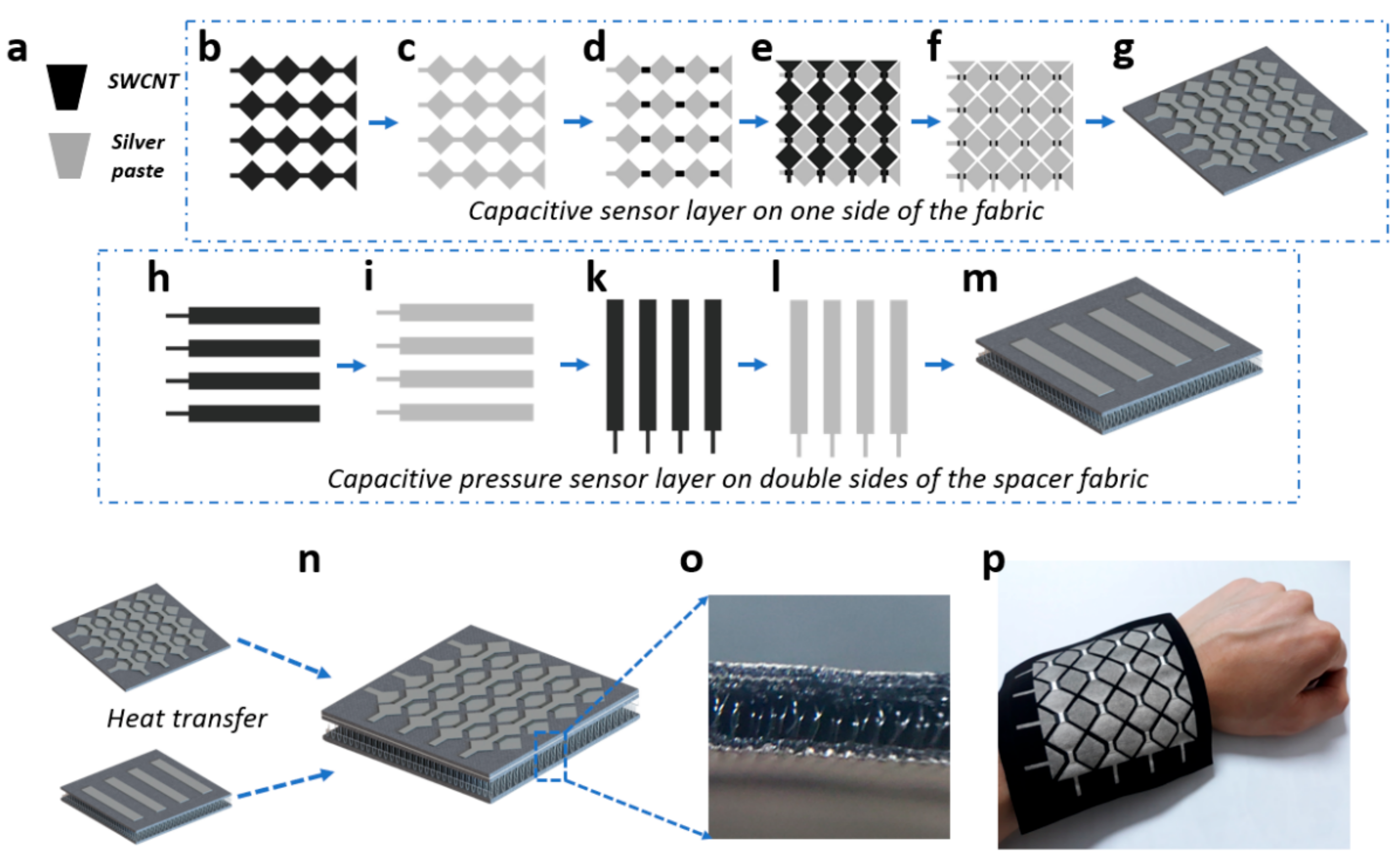
2.2. Fabrications of the Sensor Layers
3. Experimental
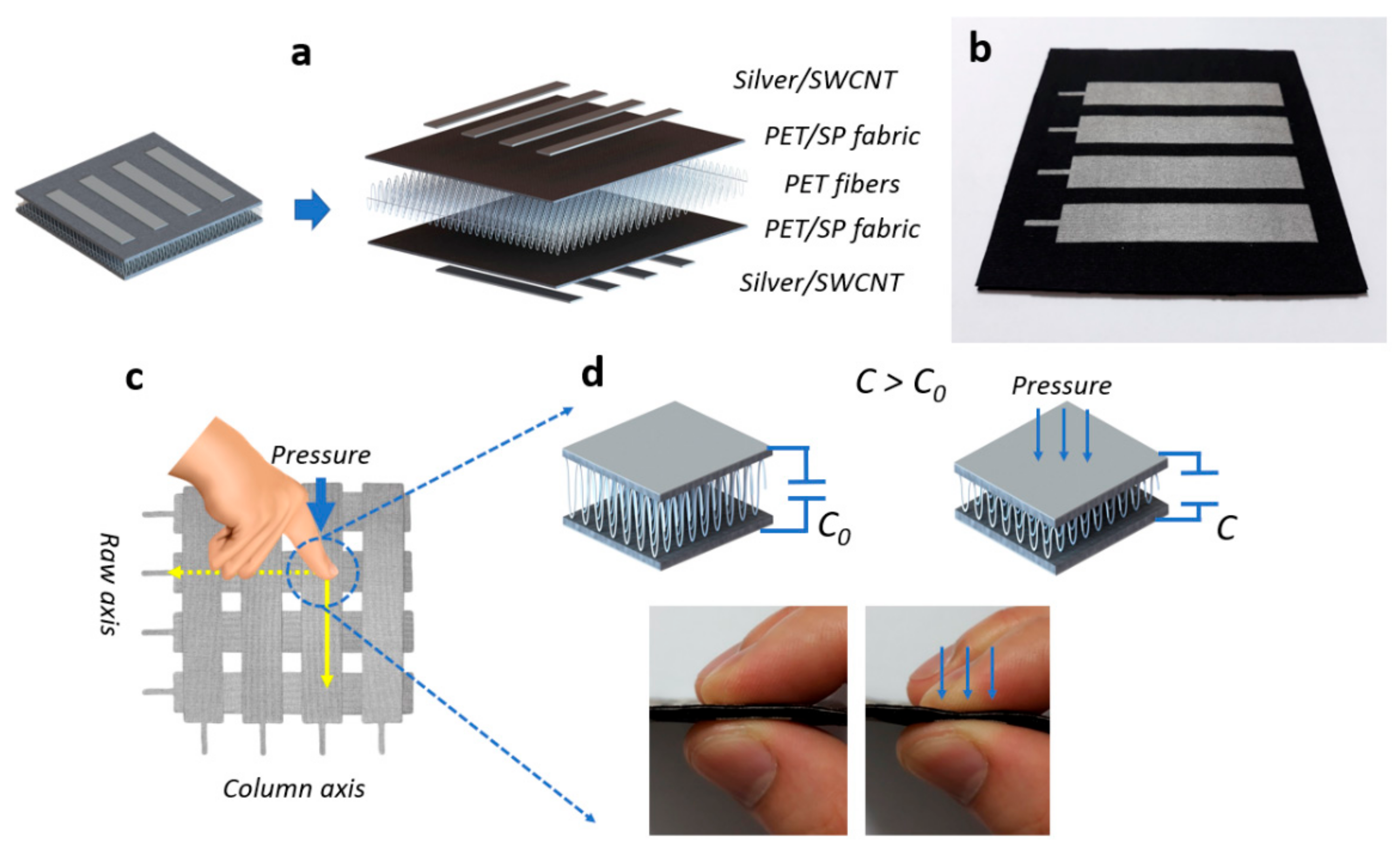
3.1. Structure
3.1.1. The Capacitive Touch Sensor Layer
3.1.2. The Capacitive Pressure Sensor Layer
3.2. Results and Discussion
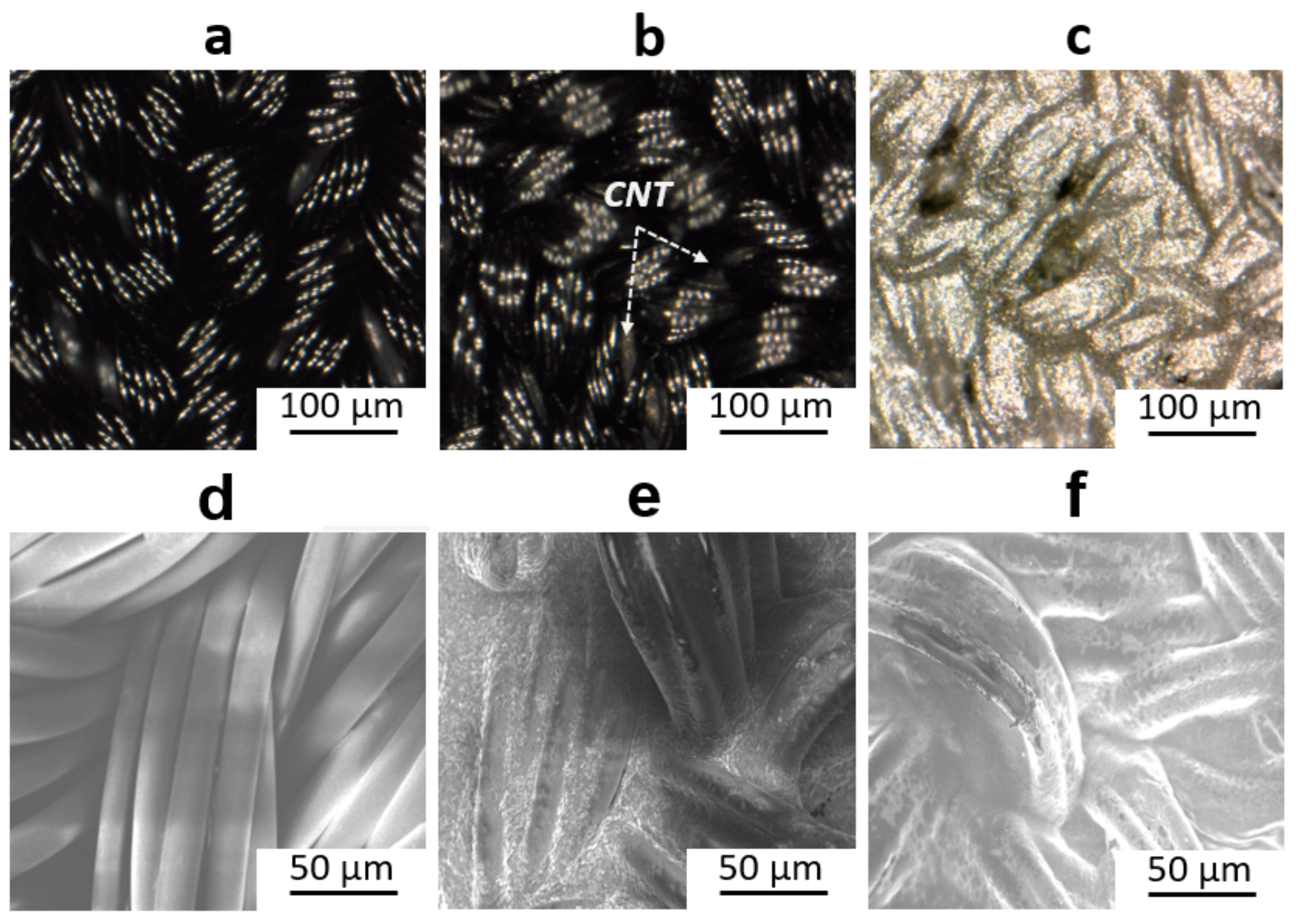
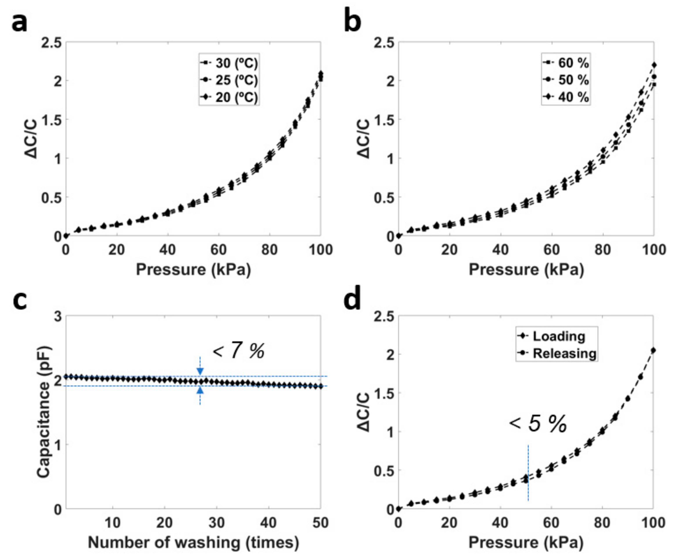
3.2.1. Characterization of the e-Fabric Skin
3.2.2. e-Fabric Skin in a Real Application
4. Conclusions
Supplementary Materials
Author Contributions
Funding
Conflicts of Interest
References
- Xue, X.; Fu, Y.; Wang, Q.; Xing, L.; Zhang, Y. Outputting Olfactory Bionic Electric Impulse by PANI/PTFE/PANI Sandwich Nanostructures and their Application as Flexible, Smelling Electronic Skin. Adv. Funct. Mater. 2016, 26, 3128–3138. [Google Scholar] [CrossRef]
- Larson, C.; Peele, B.; Li, S.; Robinson, S.; Totaro, M.; Beccai, L.; Mazzolai, B.; Shepherd, R. Highly stretchable electroluminescent skin for optical signaling and tactile sensing. Science 2016, 351, 1071–1074. [Google Scholar] [CrossRef] [PubMed]
- Byun, J.; Lee, Y.; Yoon, J.; Lee, B.; Oh, E.; Chung, S.; Lee, T.; Cho, K.-J.; Kim, J.; Hong, Y. Electronic skins for soft, compact, reversible assembly of wirelessly activated fully soft robots. Sci. Robot. 2018, 3, 9020. [Google Scholar] [CrossRef]
- Chen, Y.; Lu, B.; Chen, Y.; Feng, X. Breathable and Stretchable Temperature Sensors Inspired by Skin. Sci. Rep. 2015, 5, 11505. [Google Scholar] [CrossRef]
- Wang, C.; Sim, K.; Chen, J.; Kim, H.; Rao, Z.; Li, Y.; Chen, W.; Song, J.; Verduzco, R.; Yu, C. Soft Ultrathin Electronics Innervated Adaptive Fully Soft Robots. Adv. Mater. 2018, 30, 1706695. [Google Scholar] [CrossRef]
- Wang, L.; Yang, Y.; Chen, Y.; Majidi, C.; Lida, F.; Askounis, E.; Pei, Q. Controllable and reversible tuning of material rigidity for robot applications. Mater. Today 2018, 21, 563–576. [Google Scholar] [CrossRef]
- Xie, M.; Hisano, K.; Zhu, M.; Toyoshi, T.; Pan, M.; Okada, S.; Tsutsumi, O.; Kawamura, S.; Bowen, C. Flexible Multifunctional Sensors for Wearable and Robotic Applications. Adv. Mater. Technol. 2019, 4, 1800626. [Google Scholar] [CrossRef]
- Wang, X.; Liu, Z.; Zhang, T. Flexible Sensing Electronics for Wearable/Attachable Health Monitoring. Small 2017, 13, 1602790. [Google Scholar] [CrossRef]
- Qi, K.; He, J.; Wang, H.; Zhou, Y.; You, X.; Nan, N.; Shao, W.; Wang, L.; Ding, B.; Cui, S. A Highly Stretchable Nanofiber-Based Electronic Skin with Pressure-, Strain-, and Flexion-Sensitive Properties for Health and Motion Monitoring. ACS Appl. Mater. Interfaces 2017, 9, 42951–42960. [Google Scholar] [CrossRef]
- Trung, T.Q.; Lee, N.-E. Flexible and Stretchable Physical Sensor Integrated Platforms for Wearable Human-Activity Monitoringand Personal Healthcare. Adv. Mater. 2016, 28, 4338–4372. [Google Scholar] [CrossRef]
- Zhang, J.; Wan, L.; Gao, Y.; Fang, X.; Lu, T.; Pan, L.; Xuan, F. Highly Stretchable and Self-Healable MXene/Polyvinyl Alcohol Hydrogel Electrode for Wearable Capacitive Electronic Skin. Adv. Electron. Mater. 2019, 5, 1900285. [Google Scholar] [CrossRef]
- Lopes, P.A.; Paisana, H.; Almeida, A.T.D.; Majidi, C.; Tavakoli, M. Hydroprinted Electronics: Ultrathin Stretchable Ag–In–Ga E-Skin for Bioelectronics and Human–Machine Interaction. ACS Appl. Mater. Interfaces 2018, 10, 38760–38768. [Google Scholar] [CrossRef]
- Wang, J.; Lin, M.-F.; Park, S.; Lee, P.S. Deformable conductors for human–machine interface. Mater. Today 2018, 21, 508–526. [Google Scholar] [CrossRef]
- Nawrocki, R.A.; Matsuhisa, N.; Yokota, T.; Someya, T. 300-nm Imperceptible, Ultrafl exible, and Biocompatible e-Skin Fit with Tactile Sensors and Organic Transistors. Adv. Electron. Mater. 2016, 2, 1500452. [Google Scholar] [CrossRef]
- Cao, J.; Lu, C.; Zhuang, J.; Liu, M.; Zhang, X.; Yu, Y.; Tao, Q. Multiple Hydrogen Bonding Enables the Self-Healing of Sensors for Human-Machine Interactions. Angew. Chem. Int. Ed. 2017, 56, 8795–8800. [Google Scholar] [CrossRef]
- Wang, H.; Ma, X.; Hao, Y. Electronic Devices for Human-Machine Interfaces. Adv. Mater. Interfaces 2017, 4, 1600709. [Google Scholar] [CrossRef]
- Wu, J.; Wang, H.; Su, Z.; Zhang, M.; Hu, X.; Wang, Y.; Wang, Z.; Zhong, B.; Zhou, W.; Liu, J.; et al. Highly Flexible and Sensitive Wearable E-Skin Based on Graphite Nanoplatelet and Polyurethane Nanocomposite Films in Mass Industry Production Available. ACS Appl. Mater. Interfaces 2017, 9, 38745–38754. [Google Scholar] [CrossRef]
- Wang, B.; Facchetti, A. Mechanically Flexible Conductors for Stretchable and Wearable E-Skin and E-Textile Devices. Adv. Mater. 2019, 1901408. [Google Scholar] [CrossRef]
- Kou, H.; Zhang, L.; Tan, Q.; Liu, G.; Dong, H.; Zhang, W.; Xiong, J. Wireless wide-range pressure sensor based on graphene/PDMS sponge for tactile monitoring. Sci. Rep. 2019, 9, 1–7. [Google Scholar] [CrossRef]
- Schwartz, G.; Tee, B.C.-K.; Mei, J.; Appleton, A.L.; Kim, D.H.; Wang, H.; Bao, Z. Flexible polymer transistors with high pressure sensitivity for application in electronic skin and health monitoring. Nat. Commun. 2013, 4, 1–8. [Google Scholar] [CrossRef]
- Wan, Y.; Qiu, Z.; Huang, J.; Yang, J.; Wang, Q.; Lu, P.; Yang, J.; Zhang, J.; Huang, S.; Wu, Z.; et al. Natural Plant Materials as Dielectric Layer for Highly Sensitive Flexible Electronic Skin. Small 2018, 14, 1801657. [Google Scholar] [CrossRef] [PubMed]
- Bae, G.Y.; Han, J.T.; Lee, G.; Lee, S.; Kim, S.W.; Park, S.; Kwon, J.; Jung, S.; Cho, K. Pressure/Temperature Sensing Bimodal Electronic Skin with Stimulus Discriminability and Linear Sensitivity. Adv. Mater. 2018, 30, 1803388. [Google Scholar] [CrossRef] [PubMed]
- Kim, J.; Lee, M.; Shim, H.J.; Ghaffari, R.; Cho, H.R.; Son, D.; Jung, Y.H.; Soh, M.; Choi, C.; Jung, S.; et al. Stretchable silicon nanoribbon electronics for skin prosthesis. Nat. Commun. 2014, 5, 1–11. [Google Scholar] [CrossRef] [PubMed]
- Zou, Z.; Zhu, C.; Li, Y.; Lei, X.; Zhang, W.; Xiao, J. Rehealable, fully recyclable, and malleable electronic skin enabled by dynamic covalent thermoset nanocomposite. Sci. Adv. 2018, 4, 0508. [Google Scholar] [CrossRef]
- You, I.; Choi, S.-E.; Hwang, H.; Han, S.W.; Kim, J.W.; Jeong, U. E-Skin Tactile Sensor Matrix Pixelated by Position-Registered Conductive Microparticles Creating Pressure-Sensitive Selectors. Adv. Funct. Mater. 2018, 28, 1801858. [Google Scholar] [CrossRef]
- Wu, R.; Ma, L.; Patil, A.; Hou, C.; Zhu, S.; Fan, X.; Lin, H.; Yu, W.; Guo, W.; Liu, X.Y. All-Textile Electronic Skin Enabled by Highly Elastic Spacer Fabric and Conductive Fibers. ACS Appl. Mater. Interfaces 2019, 11, 33336–33346. [Google Scholar] [CrossRef]
- Guo, X.; Huang, Y.; Zhao, Y.; Mao, L.; Gao, L.; Pan, W.; Zhang, Y.; Liu, P. Highly stretchable strain sensor based on SWCNTs/CB synergistic conductive network for wearable human-activity monitoring and recognition. Smart Mater. Struct. 2017, 26, 095017. [Google Scholar] [CrossRef]
- Park, S.; Vosguerichian, M.; Bao, Z. A review of fabrication and applications of carbon nanotube film-based flexible electronics. Nanoscale 2013, 5, 1727–1752. [Google Scholar] [CrossRef]
- Schroeder, V.; Savagatrup, S.; He, M.; Lin, S.; Swager, T.M. Carbon Nanotube Chemical Sensors. Chem. Rev. 2019, 119, 599–663. [Google Scholar] [CrossRef]
- Schneider, M.; Koos, E.; Willenbacher, N. Highly conductive, printable pastes from capillary suspensions. Sci. Rep. 2016, 6, 31367. [Google Scholar] [CrossRef]
- Wen, J.; Tian, Y.; Hao, C.; Wang, S.; Mei, Z.; Wu, W.; Lu, J.; Zheng, Z.; Tian, Y. Fabrication of high performance printed flexible conductors by doping of polyaniline nanomaterials into silver paste. J. Mater. Chem. C 2019, 7, 1188–1197. [Google Scholar] [CrossRef]
- Liang, J.; Tong, K.; Pei, Q. A Water-Based Silver-Nanowire Screen-Print Ink for the Fabrication of Stretchable Conductors and Wearable Thin-Film Transistors. Adv. Mater. 2016, 28, 5986–5996. [Google Scholar] [CrossRef] [PubMed]
- Lansdown, A. Silver in Health Care: Antimicrobial Effects and Safety in Use. In Biofunctional Textiles and the Skin, 1st ed.; Hipler, U.-C., Elsner, P., Eds.; Karger: Basel, Switzerland, 2006; Volume 33, pp. 17–34. [Google Scholar]
- Zhang, Y.; Lin, Z.; Huang, X.; You, X.; Ye, J.; Wu, H. Highly sensitive capacitive pressure sensor with elastic metallized sponge. Smart Mater. Struct. 2019, 28, 105023. [Google Scholar] [CrossRef]
- SWCNT. Available online: http://www.khchem.com/ (accessed on 22 January 2020).
- DM-SIP-2001. Available online: https://www.dycotecmaterials.com/product/dm-sip-2001/ (accessed on 22 January 2020).
- Takamatsu, S.; Lonjaret, T.; Ismailova, E.; Masuda, A.; Itoh, T.; Malliaras, G.G. Wearable Keyboard Using Conducting Polymer Electrodes on Textiles. Adv. Mater. 2016, 28, 4485–4488. [Google Scholar] [CrossRef] [PubMed]
- Lee, J.Y.; Won, B.Y.; Park, H.G. Label-Free Multiplex DNA Detection Utilizing Projected Capacitive Touchscreen. Biotechnol. J. 2017, 13, 1700362. [Google Scholar] [CrossRef] [PubMed]
- Ferri, J.; Lidon-Roger, J.V.; Moreno, J.; Martinez, G.; Garcia-Breijo, E. A Wearable Textile 2D Touchpad Sensor Based on Screen-Printing Technology. Materials 2017, 10, 1450. [Google Scholar] [CrossRef]
- Lu, X.; Li, X.; Zhang, F.; Yang, J.; Wang, S.; Wang, H.; Bao, W.; Chen, R. A Novel Proximity Sensor Based on Parallel Plate Capacitance. IEEE Sens. J. 2018, 18, 7015–7022. [Google Scholar] [CrossRef]
- Kang, M.; Kim, J.; Jang, B.; Chae, Y.; Kim, J.-H.; Ahn, J.-H. Graphene-Based Three-Dimensional Capacitive Touch Sensor for Wearable Electronics. ACS Nano 2017, 11, 7950–7957. [Google Scholar] [CrossRef]
- Jin, H.; Jung, S.; Kim, J.; Heo, S.; Lim, J.; Park, W.; Chu, H.Y.; Bien, F.; Park, K. Stretchable Dual-Capacitor Multi-Sensor for Touch-Curvature-Pressure-Strain Sensing. Sci. Rep. 2017, 7, 1–8. [Google Scholar] [CrossRef]
- Zhu, M.; Huang, Y.; Ng, W.S.; Liu, J.; Wang, Z.; Wang, Z.; Hu, H.; Zhi, C. 3D spacer fabric based multifunctional triboelectric nanogenerator with great feasibility for mechanized large-scale production. Nano Energy 2016, 27, 439–446. [Google Scholar] [CrossRef]
- Matsouka, D.; Vassiliadis, S.; Mitilineos, S.; Stathopoulos, N.; Siores, E. Three-dimensional weft-knitted textile fabricsbased capacitors. J. Text. Inst. 2018, 109, 98–105. [Google Scholar]
- Wannenburg, J.; Malekian, R.; Hancke, G.P. Wireless Capacitive-Based ECG Sensing for Feature Extraction and Mobile Health Monitoring. IEEE Sens. J. 2018, 18, 6023–6032. [Google Scholar] [CrossRef]
- Xu, F.; Li, X.; Shi, Y.; Li, L.; Wang, W.; He, L.; Liu, R. Recent Developments for Flexible Pressure Sensors: A Review. Micromachines 2018, 9, 580. [Google Scholar] [CrossRef] [PubMed]
- Yao, S.; Swetha, P.; Zhu, Y. Nanomaterial-Enabled Wearable Sensors for Healthcare. Adv. Healthc. Mater. 2018, 7, 1700889. [Google Scholar] [CrossRef] [PubMed]
- Atalay, O.; Atalay, A.; Gafford, J.; Walsh, C. A Highly Sensitive Capacitive-Based Soft Pressure Sensor Based on a Conductive Fabric and a Microporous Dielectric Layer. Adv. Mater. Technol. 2018, 3, 1700237. [Google Scholar] [CrossRef]
- He, Z.; Chen, W.; Liang, B.; Liu, C.; Yang, L.; Lu, D.; Mo, Z.; Zhu, H.; Tang, Z.; Gui, X. Capacitive Pressure Sensor with High Sensitivity and Fast Response to Dynamic Interaction Based on Graphene and Porous Nylon Networks. ACS Appl. Mater. Interfaces 2018, 10, 12816–12823. [Google Scholar] [CrossRef]


© 2020 by the authors. Licensee MDPI, Basel, Switzerland. This article is an open access article distributed under the terms and conditions of the Creative Commons Attribution (CC BY) license (http://creativecommons.org/licenses/by/4.0/).
Share and Cite
Vu, C.C.; Kim, J. Simultaneous Sensing of Touch and Pressure by Using Highly Elastic e-Fabrics. Appl. Sci. 2020, 10, 989. https://doi.org/10.3390/app10030989
Vu CC, Kim J. Simultaneous Sensing of Touch and Pressure by Using Highly Elastic e-Fabrics. Applied Sciences. 2020; 10(3):989. https://doi.org/10.3390/app10030989
Chicago/Turabian StyleVu, Chi Cuong, and Jooyong Kim. 2020. "Simultaneous Sensing of Touch and Pressure by Using Highly Elastic e-Fabrics" Applied Sciences 10, no. 3: 989. https://doi.org/10.3390/app10030989
APA StyleVu, C. C., & Kim, J. (2020). Simultaneous Sensing of Touch and Pressure by Using Highly Elastic e-Fabrics. Applied Sciences, 10(3), 989. https://doi.org/10.3390/app10030989