1. Introduction
A massive MIMO (multiple-input multiple-output) system entails a large number (tens or hundreds) of base station antennas serving a much smaller number of terminals. These systems demonstrate large gains in spectral and energy efficiency compared with the conventional MIMO technology [
1]. Massive MIMO (multiple-input multiple-output) is no longer a "wild" or "promising" concept for future cellular networks. In 2018, the key ingredients of Massive MIMO have made it into the 5G standard. The development of fully digital Massive MIMO arrays for mmWave frequencies is well underway [
2]. However, its research is prohibitively complicated and costly. In a few years, maybe Massive MIMO with fully digital transceivers will be a mainstream feature at both sub-6 GHz and mmWave frequencies.
In [
3], researchers focused on new communication paradigms arising in massive multiple-input-multiple-output systems where the antenna array at the base station is of extremely large dimension. The main contributions of [
3] are the design of low complexity scheme of multi-antenna transceiver and evaluate the bit-error-rate performance of the transceivers in crowded xMaMIMO scenarios. However, the size of the antenna array of the base station in this solution is extremely large, which will cause great equipment costs.
A massive MIMO system entails a large number (tens or hundreds) of base station antennas serving a much smaller number of terminals. As the number of antennas grows, the performance of a massive MIMO system gets limited by the interference caused by pilot contamination. Ashikhmin and Marzetta proposed (under the name of Pilot Contamination Precoding) large scale fading precoding (LSFP) and large scale fading decoding (LSFD) based on limited cooperation between base stations [
1].
In [
1], researchers focused on the performance gain of the uplink large scale fading decoding in the case of a finite number of base station antennas. It shows that the performance can be improved further by optimizing the transmission powers of the users and presents decentralized LSFD that uses limited cooperation between neighboring cells. However, the research is focus on the transmission performance of the uplink, and the performance optimization of the downlink is not fully considered.
As the number of antennas grows, however, the performance of a massive MIMO system gets limited by the interference, contamination and noise. The increasing demands for higher data-rate transmission in cellular networks bring the attentions to Large-scale antenna system (LSAS). LSAS demonstrates large gain in spectral-efficiency and energy-efficiency compared with conventional MIMO schemes [
4].
In [
5], a multi-cell cooperation method, called pilot contamination precoding (PCP), was proposed. It was found that in a single cell LSAS, when the number of antennas tends to infinity, the communication performance can be idealized, and noise and interference can be completely eliminated. However, when turning to multi-cell LSAS, the system performance is limited by directed inter-cell interference, resulted from unavoidable re-use of nonorthogonal pilot sequences in different cells. This effect is called pilot contamination. In [
6], it was observed that if a channel has spatial correlation, then one can use this correlation to drastically reduce the pilot contamination interference in the asymptotic regime as M → ∞.
Until recently, it was believed that as the number of base station antennas tends to infinity, the performance of such systems is limited by directed inter-cellular interference caused by unavoidable re-use of training sequences (pilot contamination) by users in different cells. Large-scale fading precoding (LSFP) leads to the effective elimination of inter-cell interference. Crucially, the combining coefficients of LSFP depend only on the large-scale fading coefficients between the users and the base stations. These coefficients change slowly and their number does not depend on the number of base station antennas. Thus, the traffic between base stations stays constant even if the number of antennas tends to infinity. In [
7], researchers derived a capacity lower bound for massive MIMO systems with LSFP and a finite number of base station antennas and considered optimal and suboptimal LSFP precodings that take into account all sources of interference. The simulations results showed that LSFP provides significant gain even for the case of moderate number of base station antennas [
7].
However, the above anti-interference precoding has good performance only for a large number of antennas at a base station, reaching the value of hundreds to thousands, which increases the base station equipment costs and operating costs, and causes difficulties huge power consumption in practical applications. Namely, in order to improve the communication quality, hundreds of antennas need to be used, thus, the design complexity of the antenna array becomes too high.
On the other hand, channel inversion represents a multi-user channel modulation technology. The vector signal generated between a user and a base station is used to form an inverse channel matrix so that the channels of each user reach the equilibrium during the transmission [
8]. In [
9], researchers compared the MMSE (minimum mean squared error) channel inversion algorithm and BMSN (Block Maximum Signal-to-Noise ratio) algorithm, which commonly utilizes the channel regularization with the pseudo-noise in the MU-MIMO transmission. The performance evaluation can be carried out through computer simulation. In [
10], researchers applied the regularized channel inversion (RCI) combined with one of the 5G waveform candidates, namely generalized frequency division multiplexing (GFDM), in multiuser MIMO downlink systems and presents how the RCI in the multiuser MIMO-GFDM systems performs such good results as the RCI implemented in the multiuser MIMO-OFDM (Orthogonal Frequency Division Multiplexing) systems based on bit error rate (BER) parameter without causing a significant increase in system complexity.
The design idea of the precoding LSFP based on the zero-forcing algorithm is relatively simple, but it can only effectively eliminate interference such as pilot pollution when the number of base station antennas is very large. Optimizing the design of the precoding LSFP can ensure that interference is effectively eliminated. However, it needs to increase the power of the transmitting device to achieve efficient communication.
Aiming at the problem that the number of base station antennas of existing LSFP precoding is too large, the construction cost is too high. Based on the zero-forcing precoding algorithm and the optimized precoding algorithm, this paper applies channel inversion to improve and optimize the precoding. In the case of fewer base station antennas, interference such as pilot pollution and noise is suppressed, and the channel transmission rate is not affected at the same time, thereby achieving the purpose of further increasing the system rate and increasing the SINR.
In this work, channel inversion technology is used to improve the standard large scale fading precoding (LSFP), obtaining an improved anti-interference precoding, which can effectively eliminate pilot contamination, noise and interference using a small number of antennas. First, we applied the channel inversion technique to derive the theoretical formula for the zero-forcing large scale fading precoding algorithm to obtain its SINR expression. Under ideal circumstances, we analyzed and proved that the improved zero-forcing precoding can achieve the ideal anti-interference performance. The communication transmission rate performance was verified in the simulation. Secondly, the channel inversion technique was used to derive the theoretical formula of the optimized precoding algorithm. The SINR expression was obtained. The performance of the communication transmission rate was verified in the simulation. Finally, the regularized channel inversion technique was used to derive the theoretical formula for the optimized precoding algorithm. Its SINR expression was obtained. The performance of the communication transmission rate was verified in simulation. The SINR simulation expression of LSAS precoding of massive MIMO system was verified by simulation. The simulation compares the precoding communication rate performance before and after improvement. The simulation results show that reducing the number of antennas has no effect on the communication transmission rate. After applying the improved method to downlink transmission precoding, the communication transmission rate can be effectively improved.
The remaining of this article is organized as follows.
Section 2 describes the system model used in this paper, including the channel model and orthogonal frequency division multiplexing scheme.
Section 3 employs the channel inversion to improve the LSFP zero-forcing precoding, optimizes the precoding algorithm and performs the theoretical analysis based on the improved anti-interference precoding matrix, and lastly, obtains the SINR and channel transmission rate.
Section 4 sets the infinite number of antennas in the asymptotic field, and performs the progressive analysis of the improved anti-interference precoding to determine the channel anti-interference transcoding technology combined with the anti-jamming precoding that can produce benefits.
Section 5 presents the simulations of the channel transmission rate in the limited antenna field and compares the performance of the improved LSFP precoding and conventional LSFP precoding.
Section 6 concludes the paper.
In this article, ZF-LSFP, A-ZF-LSFP, O-LSFP, AO-LSFP, MMSE-AO-LSFP represent zero-forcing precoding, advanced zero-forcing precoding, optimal LSFP precoding, advanced optimal LSFP precoding, MMSE pre-equalization advanced optimal LSFP precoding, respectively.
Throughout the paper, we use , , and for matrix transposition, Hermitian transposition, the trace of matrix and the (m, n)-th entry of matrix A, respectively.
2. System Model
In this paper, the LSAS is set as an OFDM based cellular mobile communication network. In this kind of cellular network, the cells within a group use different OFDM orthogonal sub-channels, and the number of cells in the group is set to L [
7]. The cell represents a regular hexagonal cell network. Each cell is equipped with a multi-antenna base station, and the base station can provide services to multiple users in the cell. The number of antennas of the base station is set to M, and each antenna is an omnidirectional antenna. The number of users in the cell is set to K, and each user terminal is equipped with an omnidirectional antenna. Accordingly, a cell constitutes a multi-user MIMO system, where K independent users can form a virtual antenna array with number of antennas K. The configuration of the base station and the user end constitutes a MIMO downlink system with the size of KM, or a MIMO uplink system with the size of MK. In the traditional single-user MIMO systems, the total rate capacity of the uplink and downlink channels of a multi-user MIMO system is proportional to min(M, K).
In the OFDM-based cellular communication network, due to frequency reuse, the channel spectrum utilization is very high and the system communication performance is greatly improved [
11]. We further assume that Orthogonal Frequency-Division Multiplexing (OFDM) is used and that in a given subcarrier we have a flat-fading channel [
7]. In order to simplify the presentation of the multi-user MIMO system and reduce complex settings, we set that all the subcarriers in the communication frequency band can be used for communication between base stations and users.
2.1. Channel Model Settings
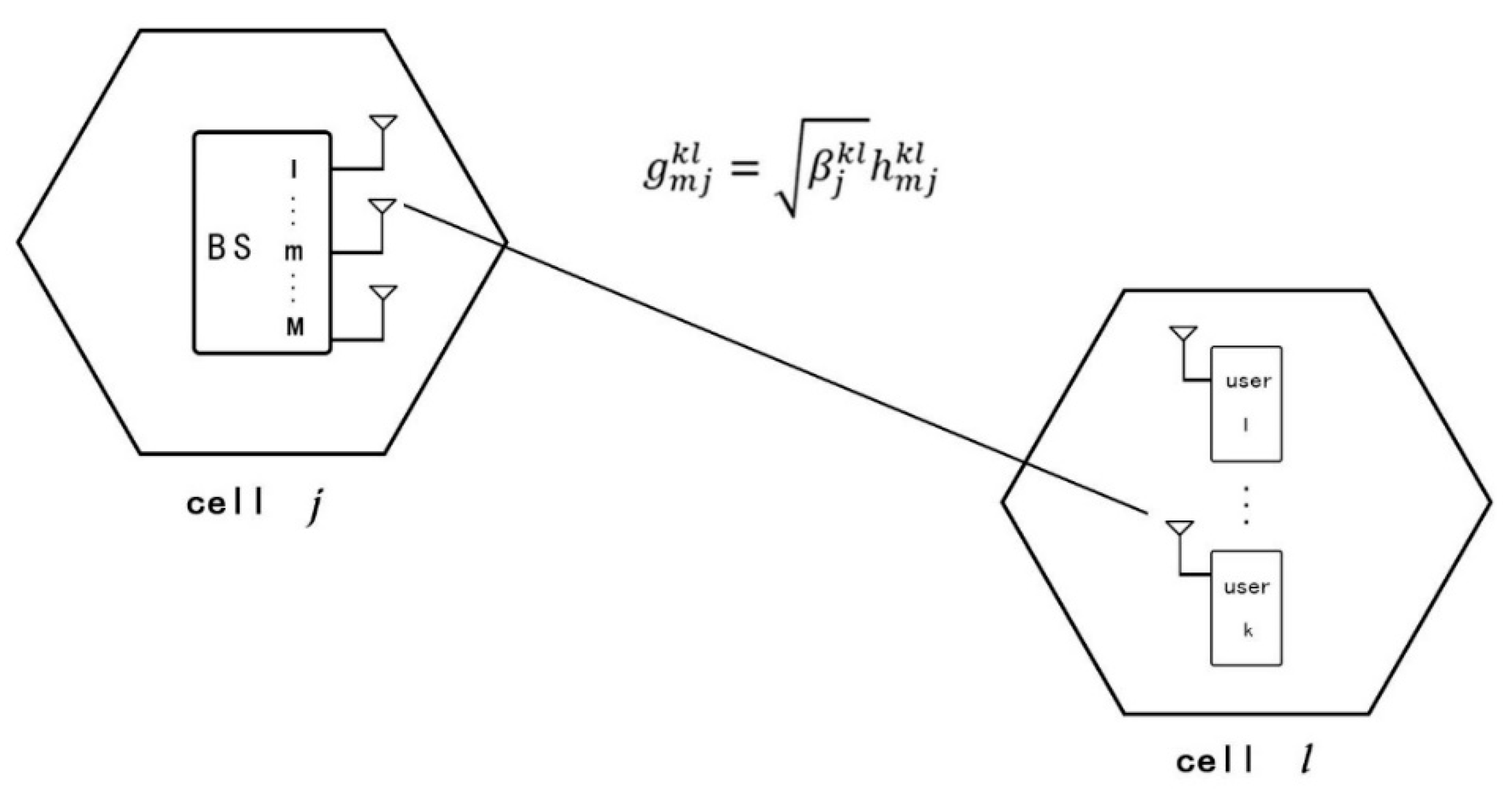
In a cellular network OFDM-based system, one block group allocates all orthogonal subcarrier channels, and the other block group reuses subcarrier channels. For a cell in a cellular network, which uses an OFDM subcarrier channel, the channel factor is expressed as a correlation operation between a large-scale attenuation factor and a small-scale attenuation factor, which is expressed as in
Figure 1.
Cell
j indicates the
j-th cell in the area group, and the number of antennas of a cell base station is M; cell
l indicates the
l-th cell in the area group, and the number of cell users is
K. The channel factor between the
m-th antenna of a base station in the
j-th cell and the
k-th user in the
l-th cell can be expressed as:
where
denotes a fast-fading factor which is a small-scale fading factor. It is mainly caused by a multipath propagation and modeled as
random variables.
Furthermore,
denotes a slow fading factor which is a large-scale fading factor, mainly caused by the building blocking. We model the large-scale fading coefficient
as a log-normal distribution based on the Urban Macro model. The specific value of
is a positive real number, which is determined by shadowing and distance between the corresponding user and base station and it is given by:
where
denotes the shadow fading coefficient with
distribution and
denotes the distance, measured in kilometer, between the
j-th BS and the
k-th user in the
l-th cell.
2.2. OFDM Duplex Setting
In this article, a multi-user MIMO system that used the OFDMA (Orthogonal Frequency Division Multiple Access) technology is studied. In the OFDMA, each user is assigned to a group of subcarriers, and the number of subcarriers for each user in each cell is defined by the system scheduling. For the sake of simplicity, it is assumed that the system model uniformly sets K users in each cell, that is, K subcarriers. The communication link between a base station and a user is divided into downlink and uplink duplex modes. We consider LSAS (large scale antenna system) with the TDD (Time Division Duplexing) protocol. The TDD protocol was set up with three steps: Tu channel was used for uplink training; Tpchannel was used for processing precoding; Td channel was used for downlink training.
In TDD, the uplink and downlink transmissions were allocated to different communication time slots and could not be performed simultaneously; thus, the transmission and reception of a user signal was completed through the assigned subcarriers. However, they were performed at different times, and the corresponding time slots could be dynamically and flexibly allocated. Due to the reciprocity of uplink transmission and downlink transmission, the MIMO technology and antenna technology could be combined with time division duplexing.
5. Simulation
The performance of anti-interference precoding was analyzed in terms of the communication transmission rate. The simulation graph represents the cumulative distribution function (CDF), which can reflect the received signal-to-interference and noise ratio and the information transmission throughput rate [
15]. In the simulation, the performance of communication transmission rate of improved and conventional precoding schemes, which includes ZF-LSFP, AZF-LSFP, O-LSFP, AO-LSFP and MMSE-AO-LSFP, is compared under different base antenna numbers.
The simulation model was based on
Section 2 channel model setting. We model the large-scale fading coefficient
as log-normal distribution based on the Urban Macro model that followed the 3GPP (3rd Generation Partnership Project) standard. Cell base stations and user settings in
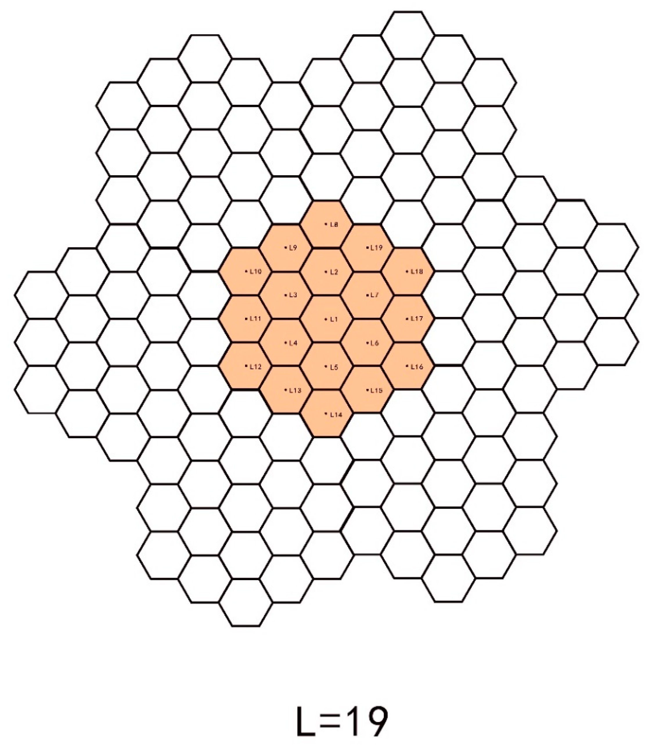
Figure 2: the number of cells contained in a single cell group was L = 19, the number of users contained in a single cell was K = 10, and the number of cell base station antennas was M. The cell was randomly distributed to ten mobile users. The cell radius was r = 1 km. The cell base station was set in the center. The mobile user was randomly located in a circular area having the base station as a center, a radius of 62.5 m.
The cell numbers in the area group were set to L1, l = 1, ⋯, 19. Each cell center point was set with two-dimensional coordinates and the L1 coordinate is L1(0,0). According to the cell radius, the coordinates of all cell center points L1(ml, nl) can be generated.
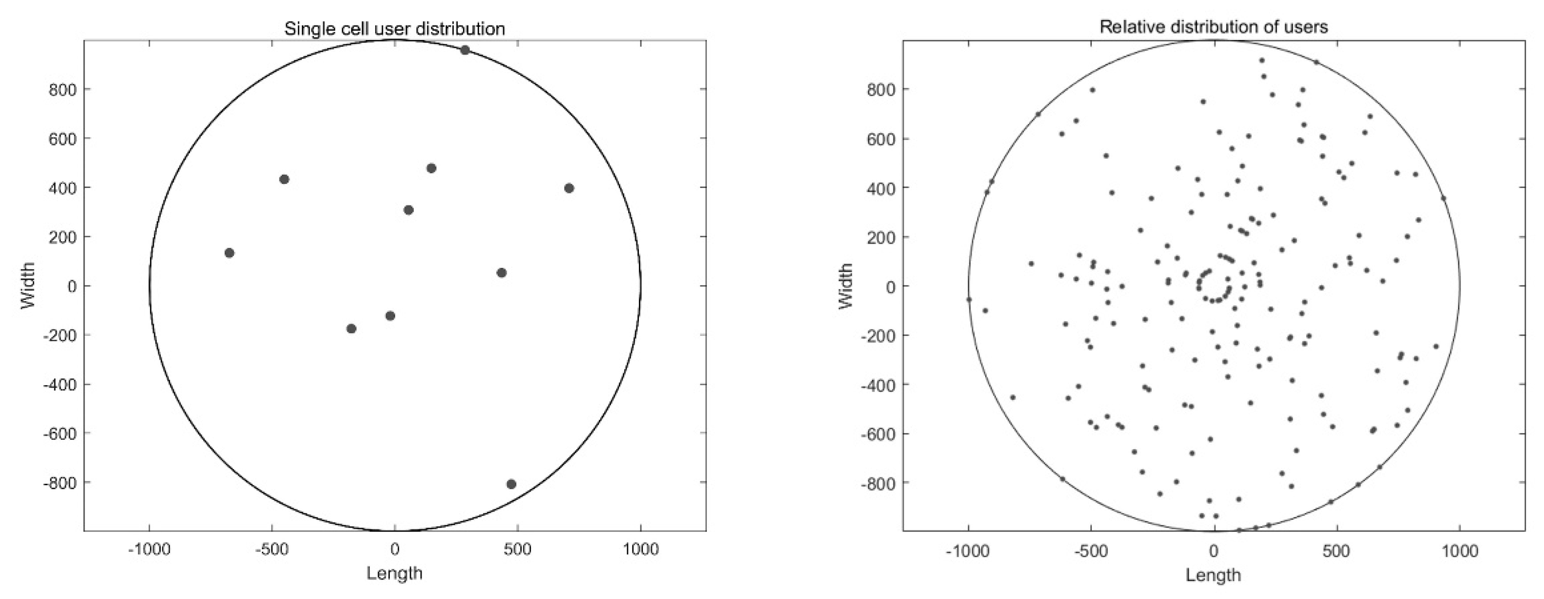
The distribution map of users of a single cell is presented in
Figure 3 left, where each dot represents a user. The user distribution range was set in the simulation, and the generated points were randomly distributed. Randomly selecting a hexagonal cell, and the center point is the base station position. The positions of 10 users in this cell are randomly generated. The user positions are evenly distributed in the cell. We eliminate the extreme case that all users are distributed at the cell edge.
A random distribution diagram of a total of 190 users grouped into 19 cells within the cellular network to which they belonged is presented in
Figure 3 right. The relative distance between a user and 19 base stations was obtained using the same principle as in spatial channel model for multiple input multiple output (MIMO) simulations of Technical specification group radio access network. There are 19 communities in the cellular network, with a total of 19 × 10 users. The location of 190 users is randomly generated in a hexagonal cell with the center point coordinate of (x,y), and a group of 10 users Substitute the coordinates of 19 center points L
1(m
l, n
l), l = 1, ⋯, 19 in turn, and obtain the coordinate of all users in each cell. Then, we can calculate the distance
according to coordinates of the
j-th BS and the
k-th user in the
l-th cell.
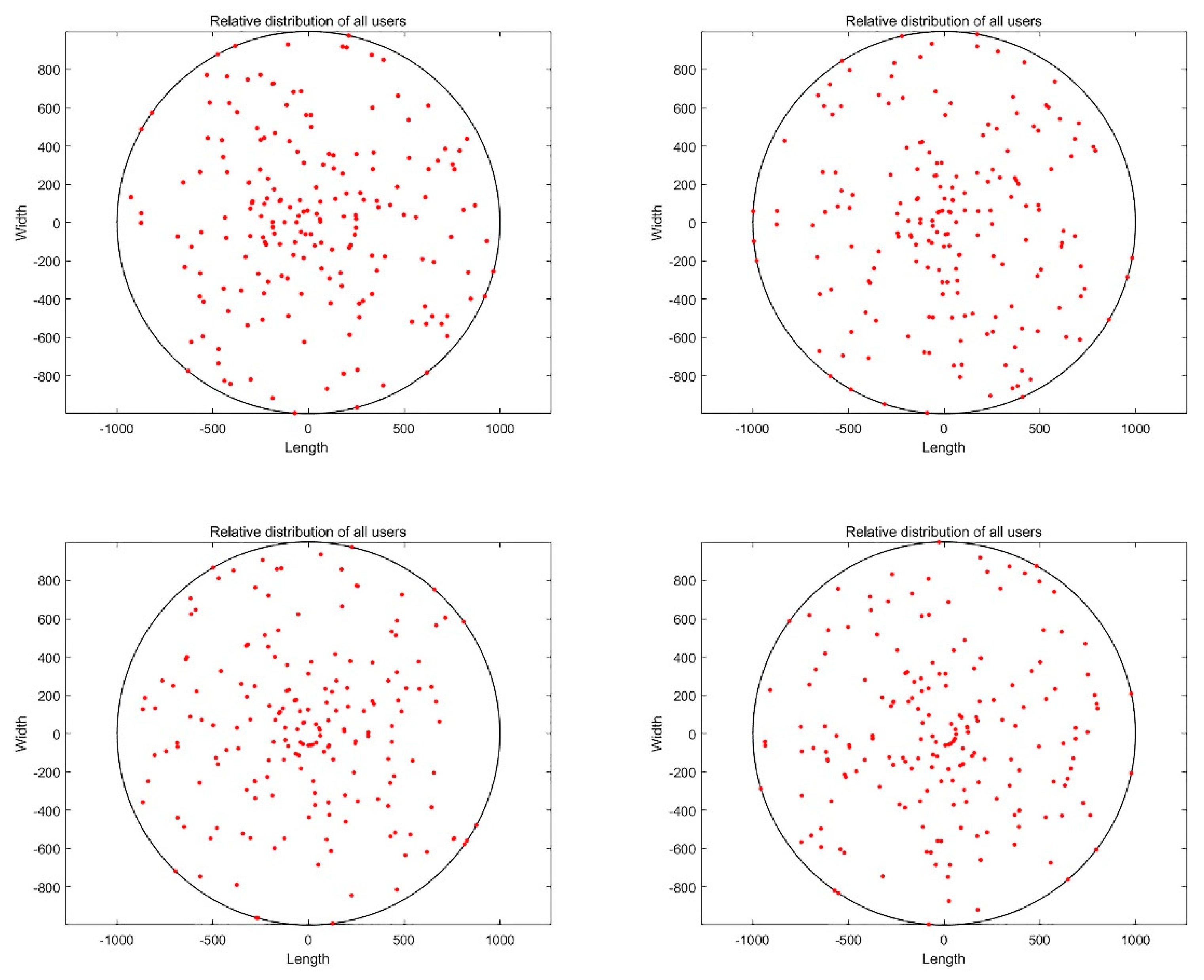
Considering the movement of end users, it was assumed that users move freely in the cell to which they belong, but irrespective of the extreme case where all users move to the edge of the cell. The distribution of users in the cell is still roughly evenly distributed. The positions of 190 users were randomly generated in the hexagonal cell with the center point coordinate of (x,y) for many times. The user position distribution changes as shown in the point in
Figure 4, which simulates the free movement of users in each cell.
According to the set system model, a large-scale fading factor was obtained using the 3GPP urban macro model, which is given by (2). Other simulation settings: the transmit powers of the BS and users were ρr = 23 dBm and ρf = 23 dBm, respectively. The noise figures of the BS and user were 5 and 10, respectively; the bandwidth was 20 MHZ.
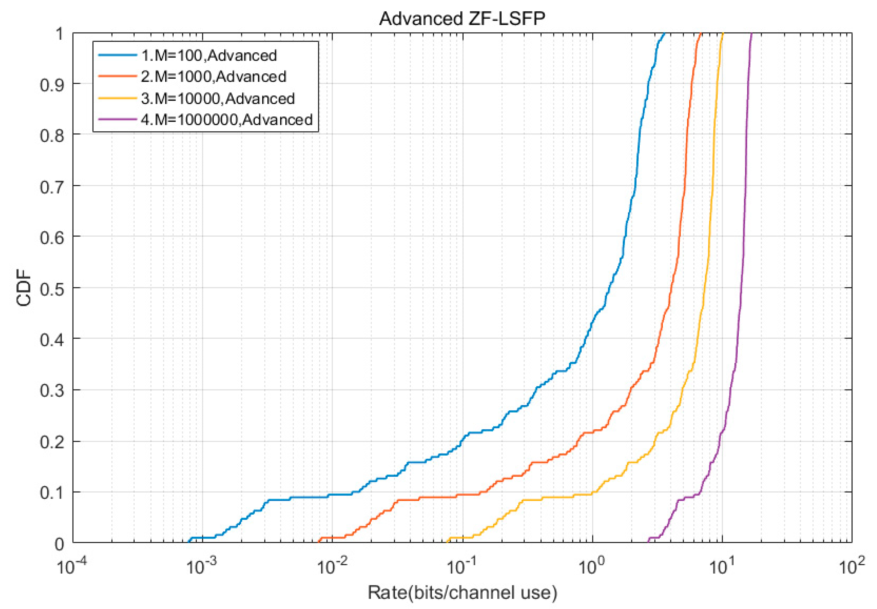
In the simulation, different numbers of base station antennas were used, M was set to 100, 1000, 10,000, and 1,000,000. Channel transmission rate can be calculated by (36). The simulation results show the lowest achievable rate in a cellular network group.
In
Figure 5, the simulation results are compared with those of the ZF-LSFP that are provided in [
4]. The comparison results show that when M reached the value of
, the achievable channel transmission rate of the A-ZF-LSFP reached the value of
, and the performance of channel transmission rate increased by 60%. When M was between
and
, the channel transmission rate of the A-ZF-LSFP increased by 90%.
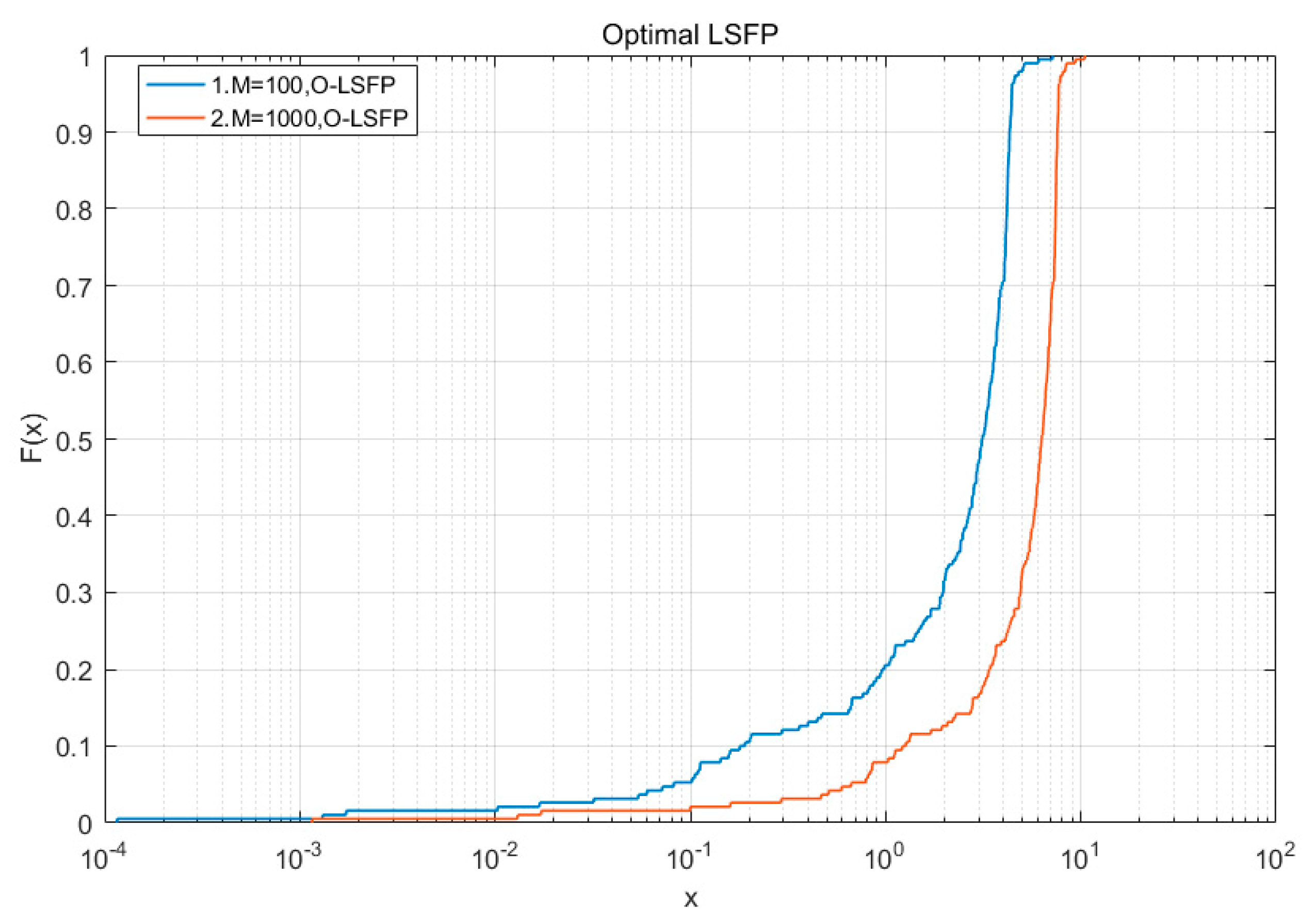
As
Figure 6 shows, when the number of antennas was 100, the probability that the unimproved optimized precoding could achieve a channel transmission rate greater than
was about 0.8, and the probability of reaching the value of
was zero; when the number of antennas was 1000, the probability that the O-LSFP could achieve a channel transmission rate greater than
was about 0.9, and the probability of reaching the value of
was close to zero.
As
Figure 7 shows, when the number of antennas was 100, the probability that the optimized precoding with channel inversion processing could achieve a channel transmission rate greater than
was about 0.9, and the probability of reaching the value of
was 0.05; when the number of antennas was 1000, the probability that the A-O-LSFP could achieve a channel transmission rate greater than
was about 0.96, and the probability of reaching the value of
was about 0.5. In the simulations, when the number of antennas was a few hundreds, the transmission rate of the A-O-LSFP was increased by at least 10%.
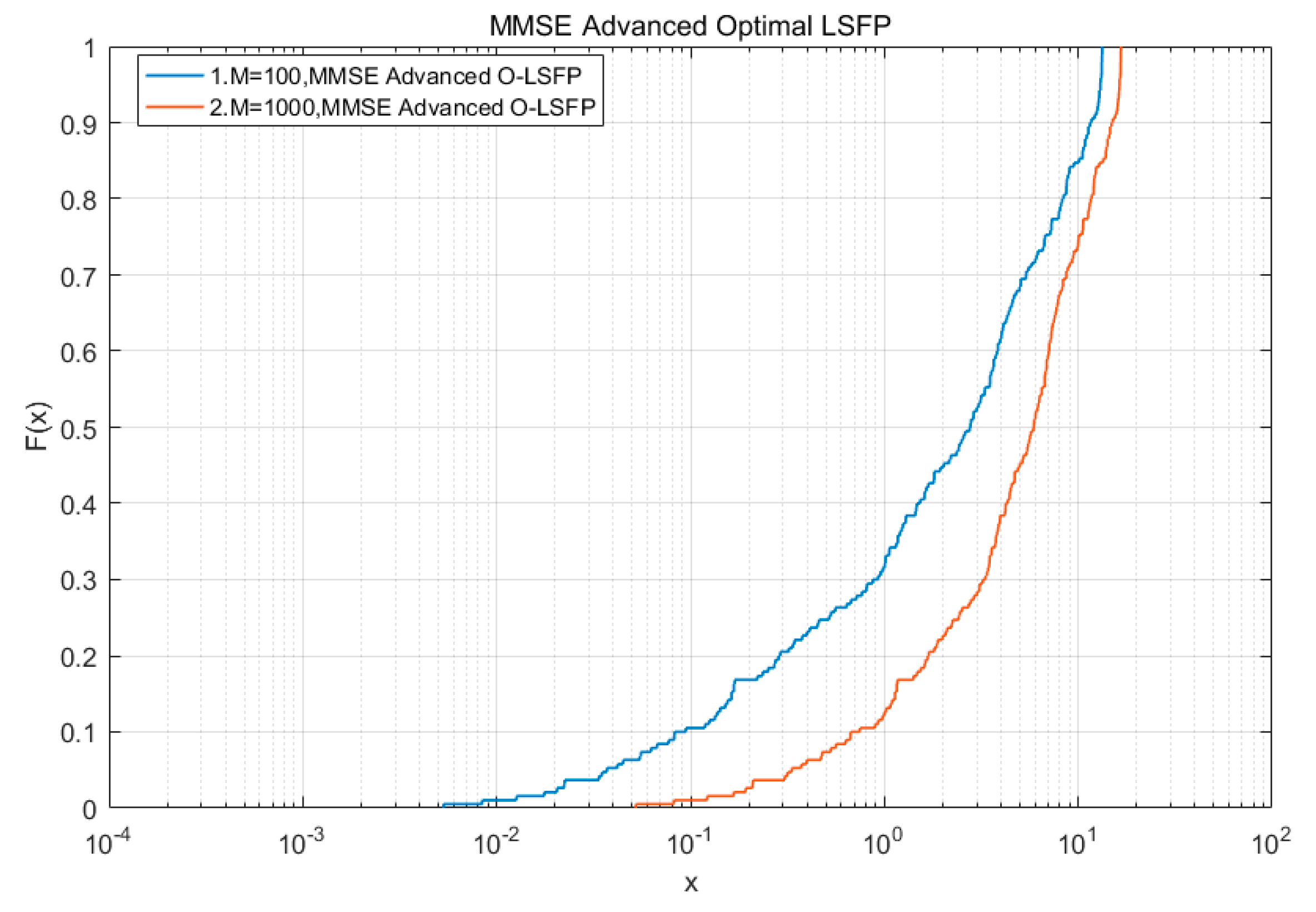
Figure 8 shows that when the number of antennas was 100, the probability that the optimized precoding with regular channel inversion processing could achieve a channel transmission rate greater than
was about 0.7, and the probability that it could reach the value of
was 0.15; when the number of antennas was 1000, the probability that the MMSE-A-O-LSFP could achieve a channel transmission rate greater than
was about 0.9, and the probability of reaching the value of
was about 0.25. The simulation results showed that when the number of antennas was about 100, the MMSE-A-O-LSFP had a probability of 15% to reach 10 times the transmission rate gain, but there was still a 10% attenuation probability. The MMSE-A-O-LSFP had a probability of reaching 10 times the transmission rate gain of 25%, and there was no attenuation of the transmission rate gain, and the improved performance is completely improved.
