Article

Influence of Phase Change Phenomena on the Performance of a Desiccant Dehumidification System

1
Department of Energy and Environmental Engineering, Interdisciplinary Graduate School of Engineering Sciences, Kyushu University, 6-1 Kasuga-koen, Kasuga-shi, Fukuoka 816-8580, Japan
2
Thermal Science and Engineering Division, International Institute of Carbon-Neutral Energy Research (I2CNER), Kyushu University, 744 Motooka, Nishi-ku, Fukuoka 819-0395, Japan
3
Department of Mechanical Engineering, Faculty of Engineering, Sebelas Maret University, Jl. Ir. Sutami 36 A, Surakarta 57126, Indonesia
*
Author to whom correspondence should be addressed.
Appl. Sci. 2020, 10(3), 868; https://doi.org/10.3390/app10030868
Submission received: 30 December 2019 / Revised: 20 January 2020 / Accepted: 23 January 2020 / Published: 27 January 2020
(This article belongs to the Special Issue Sciences and Innovations in Heat Pump/Refrigeration)

Abstract

:
Demands of standalone dehumidification systems have been increasing in order to realize energy savings in air-conditioning processes. In a desiccant dehumidification system, the water vapor from the moist air undergoes a phase change phenomenon, this being from vapor to adsorbed phase, a process analogous to latent heat exchange. The energy exchange involved in such a process is often significant—up to 80% of the total energy exchange. In this study, the influence of the phase change phenomena involved in a desiccant dehumidification system was evaluated experimentally, along with the performance investigation under low desorption air temperatures of 308, 318, 328, 338, and 345 K. The system was driven by a constant adsorption temperature of 293 K. The dehumidification ability, latent heat ratio, and latent effectiveness were employed as key performance indexes. The results showed that with the increased desorption temperature, the latent heat ratio decreased, whereas the dehumidification ability and latent effectiveness increased. The highest latent heat ratio was found to be 0.61 at the desorption temperature of 308 K, whereas the highest latent effectiveness was obtained at the desorption temperature of 345 K. A suitable temperature for the effective and efficient dehumidification was observed to be 318 K for the current system.

1. Introduction

Consideration of reducing energy consumption to drive an air conditioning system for heating [1,2], cooling [3,4], humidification [5,6], and dehumidification [7,8,9] has gained the attraction of developing an effective system that consumes less energy. For most cases, in hot and humid areas, around 20%–40% of total energy is dominated by air conditioning systems [10]. High energy is required for achieving the cooling and dehumidification load. However, a significant amount of this energy can be reduced by coupling the air conditioning system with alternative energy resources involving solar energy [11,12], wind energy [13,14], and waste heat from industrial processes [15,16]. Additionally, other than using the hybrid or coupling system, the separation of the sensible and latent load can also reduce the power inputs within the system [17]. Therefore, the current study offers an attempt in desiccant dehumidification system utilization, which could be able to handle the latent heat load individually to minimize the energy consumption by the air conditioning system. This system is expected to be used in hot and humid regions when the demand for dehumidification load is dominant.
The main issue when using the desiccant system is poor performance due to improper parameter design. Three main factors can determine the performance of the desiccant system: (1) adsorbent/ adsorbate pairs [18,19,20], (2) properties of the working fluid [21,22], and (3) design and operating conditions of the system [23,24]. The proper combination of these three parameters is expected to improve the performance of the system. It was also found that several efforts have been made by researchers to achieve this goal. The development of the desiccant dehumidification system that is driven by solar energy was implemented by Lu et al. [25]. Employing solar energy ensures not only the feasibility but also the achievement of the efficiency of the system. A novel desiccant air-conditioning system, which was coupled with the needle-impeller rotors, was modeled by Oliveira et al. [26]. Unlike the existing desiccant system, the additional needle-impeller rotor was supposed to improve the heat and mass transfer between the absorber and evaporator.
Kanoğlu et al. [27] presented an evaluation of the performance of the desiccant cooling system under different ambient temperatures and relative humidity. Adjusting ambient temperature and relative humidity affected the coefficient of performance (COP) and cooling load of the system. The performance decreases when the temperature and relative humidity is increased. Somehow it will approach a zero value when the temperature and moisture become higher. Jeong et al. [28] numerically investigated the performance of the desiccant dehumidification systems driven by a low-grade heat source. The study was aimed to determine the minimum heat source temperature to drive the system. They found that the lowest regeneration temperature of 306 K was able to drive the system. Panaras et al. [29] proposed design parameters and their effect on the performance of a solid desiccant air conditioning system. The ambient and load conditions were investigated and modeled under steady-state conditions, whereas the result validation was based on the experimental data. The critical parameter for designing the desiccant air conditioning system was the air flow rate and regeneration temperature. The proper mass flow rate and regeneration air temperature not only were downsized the desiccant sysmtem, but efficient thermal energy use was also given. Ge et al. [30] analyzed the performance of the silica gel rotary desiccant-wheel by considering the influence of the regeneration temperature. As they developed the system for a dehumidifier, the performance was evaluated regarding the removal efficiency and dehumidification capacity. They found that increasing the regeneration temperature offers the increment of removal efficiency. Additionally, they also stated that the humidity ratio significantly influences the dehumidification capacity. Lee et al. [31] found an energy reduction of 26.3% when using the solid desiccant for the mobile air conditioning system. The system was the hybrid system, which was a combination of the solid desiccant and vapor compression cycle. The presence of a desiccant system was able to split up the latent heat load from the sensible heat. Hence, the compressor power consumption reduced because of the increase of the evaporating temperature.
The above review shows that the desiccant system is promising for air conditioners; therefore, evaluating their performance would be equally important as understanding the parameter design. Because the current study focused on the desiccant dehumidification system, the latent heat became the primary consideration in performing the performance evaluation. In the adsorption/desorption process, latent heat can be defined as the heat transfer, which occurs during the phase change [32]. Only a few studies provide the effect of the latent heat on the performance of the desiccant system. This reason, therefore, gained our motivation to propose a study on the latent heat effect. Additionally, the consideration of the desorption temperature adjustment was also provided in this study. It is widely known that the increase of desorption temperature would give more dehumidification capacity [30,33,34]. However, low desorption temperature [28,35] is preferable to reduce the power consumption. It is worth considering the low desorption temperature; even so, it is still unclear whether this temperature will contribute to a significant effect on the performance of the system given the energy-saving and moisture removal ability we have discussed. From these issues, our objective is to determine the impact of the desorption air temperature and latent heat on the performance and dehumidification ability of the desiccant dehumidification system. The experiment was conducted by employing low-temperature desorption (lower than 343 K), which also reflected the low-grade energy. A recommendation for such a system was also proposed to obtain an effective and efficient operation.

2. Materials and Methods

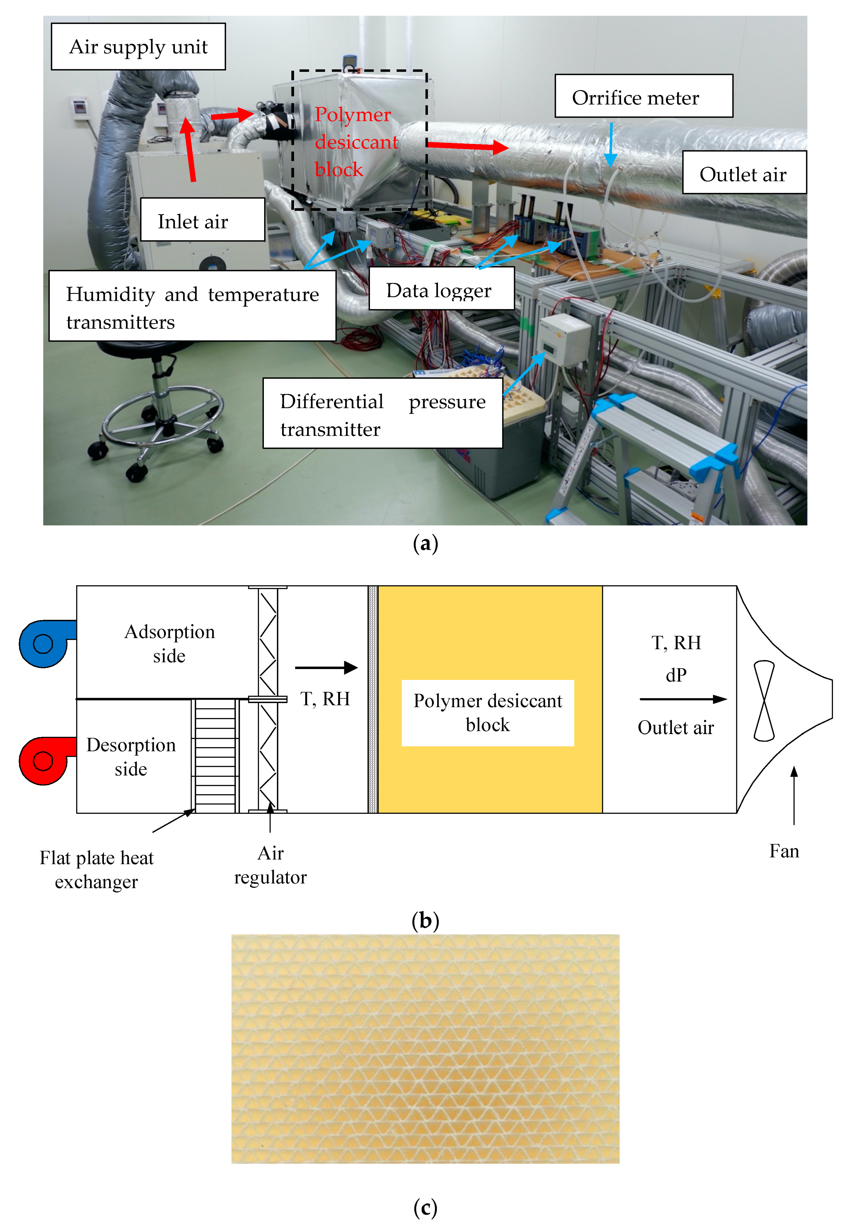
2.1. Experimental Section

Figure 1a,b show the photograph and schematic diagram of the desiccant dehumidification system, respectively. It consisted of three main parts: desiccant block, air supply unit, and measurement system. Additionally, Figure 1c portrays the structure of the polymer desiccant block.
Detailed information about the properties of the desiccant block material is provided in Table 1.
The structure of the polymer desiccant block, as shown in Figure 1c, was a sinusoidal face area. It was intended to improve the surface contact between the adsorbent and adsorbate; hence, it could enhance the heat and mass transfer inside the system. Eight desiccant blocks were packed into the cubical shape, two columns and rows for each run of the experiment. The dimension that is provided in Table 1 revealed that the cross-sectional area of the desiccant blocks was found to be 0.16 m2.
As shown in Figure 1a, the entering process of air for adsorption and desorption processes was controlled by two different air supply units, which had an accuracy of T = ± 0.05 – 1 °C and T = ± 0.5 °C and RH = ± 2% for adsorption and desorption, respectively. Each unit worked alternately by adjusting the allocation time for each process. The desorption and adsorption times were maintained at 60 min and 120 min, respectively. The mass flow rate of the system was determined by the pressure difference obtained by 0.08 m orifice diameter. Pressure transmitter, with P = 0.35 Pa + 0.6% of full-scale precision, displayed the pressure difference measured by the orifice meter. The air supply units could provide a maximum temperature of 328 K and relative humidity of 85%. Therefore, when the system required high desorption temperature, the flat plate heat exchanger can be used to increase the temperature. The humidity and temperature transmitters, HMT 333, which had an accuracy of T = ± 0.2–0.3 °C and RH = ± 1%–1.7%, were equipped within the system for humidity and temperature control at the inlet and outlet of process air. Red arrows in Figure 1a indicate the process of air flow. For better understanding, the schematic diagram of the system was added in Figure 1b. The separation between the adsorption and desorption sides was divided by using the air regulator. The installment of the temperature and humidity sensors were placed just before and after the desiccant block.
To determine the performance of the system, five different desorption temperatures; 308, 318, 328, 338, and 345 K were selected as the operating parameters. During the running of the system, the adsorption temperature and mass flow rate did not change from the value of 293 K and 0.1 m/s, respectively. Additionally, the experimental setup was installed inside the humidity chamber. It permitted the setting of the temperature and humidity ratio for process air inside the system. The environmental conditions were adjusted under 298 K and 65% for temperature and relative humidity, respectively. The adsorption and desorption processes worked continuously during the experiment. Once the process of adsorption and desorption finished, this was considered as one cycle. For all cases, it allocated 60 min for desorption and 120 min for adsorption. Table 2 summarizes the operating parameters of the experimental conditions.
The Reynolds number (Re) was calculated by
R e = ρ a U a D h μ
where ρa, Ua, Dh, and μ represent the density (kg/m3), velocity (m/s), hydraulic diameter (m), and dynamic viscosity of the air (kg/m.s), respectively.
Figure 2 draws the psychrometric chart of the current experimental point. Points 1 and 2 denote the inlet and outlet conditions of the adsorption process, respectively. Desorption inlet and outlet states are represented by spots 3 and 4, respectively.
Overall, the working principle of the desiccant dehumidification system was as follows:
(1)
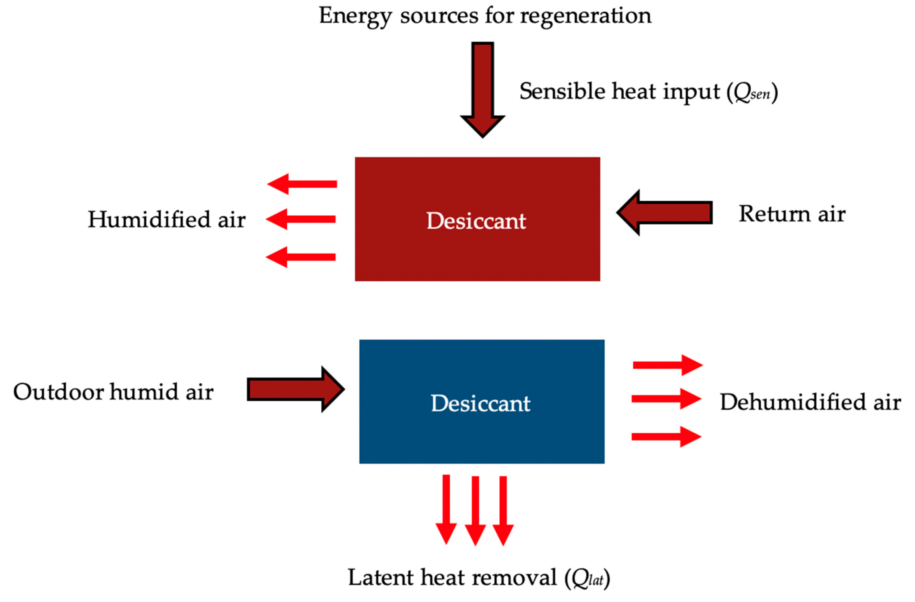
Firstly, the desiccant material was heated by the hot air, which was provided by the air supply unit for the desorption phase. This process allowed the water vapor molecules, which were trapped in the desiccant material, to evaporate. Therefore, the desiccant material was regenerated and recovered the ability of moisture adsorption.
(2)
When the desiccant material reached the equilibrium, the process was switched into the adsorption process by using the air regulator. The desiccant material adsorbed the water vapor molecules. At the same time, in the interface of the desiccant material, the heat of adsorption was released.
(3)
Lastly, the process was repeated for three up to four cycles to obtain adequate data.

2.2. Data Reduction Equations

Data on the temperature inlet-outlet, relative humidity inlet-outlet, and the pressure difference between the inlet and outlet of the air stream were essential to determine the performance indices of the desiccant dehumidification system. Collecting of the data during the experiment was performed by data logger DAQMASTER: MX 100 (accuracy = ±0.01%), which recorded the data for every 10 s. Because we had four cycles of data, the last cycle data was applied to evaluate and analyze the results. The following terms assessed the performance indices of the system:

2.2.1. Dehumidification Index

The characterization of the dehumidification system was examined by calculating the dehumidification index for adsorption and desorption process. To characterize the dehumidification index, firstly the calculation of adsorption and desorption amount of the desiccant was examined. The amount was defined as the water content removal that can be considered as the difference between the humidity ratio inlet and humidity ratio outlet. The following expressions can calculate the water content removal for each process:
d a d s =   X a d s , i n   X a d s , o u t ,   for   adsorption
d d e s =   X d e s , i n   X d e s , o u t ,   for   desorption
where d is the moisture removal capacity (kg/kg), Xin is the humidity ratio of the inlet air (kg/kg), and Xout is the humidity ratio of the outlet air (kg/kg), whereas ads and des indicate the adsorption and desorption processes. In the case of the desorption process, because the hot air brought about water vapor during the running of the system, the outlet humidity was thus higher than in the inlet, and the moisture removal became negative.
During the adsorption process, the average dehumidification index (Di) was defined as:
D i = 1 t 0 t d a d s d t
where t is the dehumidification time (s).

2.2.2. The Effect of Latent Heat on the Performance

The primary importance of the desiccant dehumidification system is its capability to reduce the moisture content of the humid air. Taking into account the handling of the moisture content, the performances were evaluated regarding the latent heat ratio and latent effectiveness. The latent effectiveness (ε) was obtained as:
ε = X a d s , i n   X a d s , o u t X a d s , i n   X i d e a l
where Xideal is the ideal humidity ratio that is calculated by considering the isenthalpic line of the humidity ratio inlet of the adsorption process under the constant’s relative humidity of the regeneration inlet conditions (kg/kg). If the water content was dehumidified completely, the ideal humidity ratio would reach the zero value. This value can be considered for the optimization of the desiccant dehumidification system [36]. The differences between the humidity ratio inlet of the adsorption process and ideal humidity ratio were referred to as the maximum dehumidification capacity of the system.
The performance of the desiccant dehumidification system, which showed the energy amount, was evaluated by using the latent heat ratio (LHR). LHR can be described as the ratio of the latent heat to the total energy (latent and sensible heat) required by the system [37]. It was given by the following equation:
L H R = Q l a t Q l a t +   Q s e n
Latent heat (Qlat) was given by
Q l a t = Q ads   =   d ads   m ˙ a   γ   =   m ˙ a   ( h in     h out )
and Sensible heat (Qsen) was given by
Q sen = Q des = m ˙ a   c p   ( T des , in     T des , out )
where Qlat is the latent heat (W), Qsen is the sensible heat (W), Qads is the average of enthalpy exchange in the adsorption process (W), Qdes is the average of heat exchange in the desorption process (W), a is the air mass flow rate (kg/s), γ is latent heat of vaporization (kJ/s), cp is specific heat of the air at bulk temperature (kJ/kg·K), Tdes,in is air inlet temperature of the desorption process (K), and Tdes,out is the air outlet temperature of the desorption process (K).

2.2.3. Uncertainty Analysis

The calculation of the uncertainty analysis was based on the statistical methods (standard deviation) introduced by Kirkup and Frenkel, 2006 [38]. The representative values of uncertainty analysis included the individual uncertainties of the measured values.
Uncertainty of Humidity Ratio (X)
The humidity ratio was given by
X = 0.62198 R H . P s P R H . P s
The uncertainty analysis was expressed as
u 2 ( X ) = ( X R H ) 2 u 2 ( R H ) + ( X P ) 2 u 2 ( P ) + ( X P s ) 2 u 2 ( P s )
where RH is the relative humidity of the air, P is the atmospheric pressure, and Ps is the saturation water vapor pressure.
Uncertainty of Dehumidification Index (Di)
The dehumidification index was calculated by Equations (2) and (3). Therefore, the uncertainty analysis for the dehumidification index was
u 2 ( D i ) = ( D i X in ) 2 u 2 ( X in ) + ( D i X out ) 2 u 2 ( X out )
Uncertainty of Latent Effectiveness (ε)
The latent effectiveness uncertainty evaluation, based on the parameters in Equation (5), was calculated as
u 2 ( ε ) = ( ε X ads ,   in ) 2 u 2 ( X ads ,   in ) + ( ε X ads ,   out ) 2 u 2 ( X ads ,   out ) + ( ε X ideal ) 2 u 2 ( X ideal )
Uncertainty of Latent Heat Ratio (LHR)
For latent heat ratio, rearranging Equations (6)–(8) formed
LHR   = Q lat Q lat + Q sen
= m ˙ a ( h in h out ) m ˙ a ( h in h out ) + m ˙ a c p ( T des , in T des , out )
= ( h in h out ) ( h in h out ) + c p ( T des , in T des , out )
The uncertainty of LHR was
u 2 ( LHR )   = ( LHR h in ) 2 u 2 ( h in ) + ( LHR h out ) 2 u 2 ( h out ) + ( LHR c p ) 2 u 2 ( c p ) + ( LHR t des , in ) 2 u 2 ( T des , in ) + ( LHR T des , out ) 2 u 2 ( T des , out )
Uncertainty of Reynolds number (Re)
Reynolds number uncertainty was given as
u 2 ( Re ) = ( Re ρ ) 2 u 2 ( ρ ) + ( Re U a ) 2 u 2 ( U a ) + ( Re D h ) 2 u 2 ( D h ) + ( Re μ ) 2 u 2 ( μ )
Table 3 collects the uncertainty values for the humidity ratio, Reynolds number (Re), dehumidification index, latent effectiveness, and latent heat ratio.

3. Results and Discussion

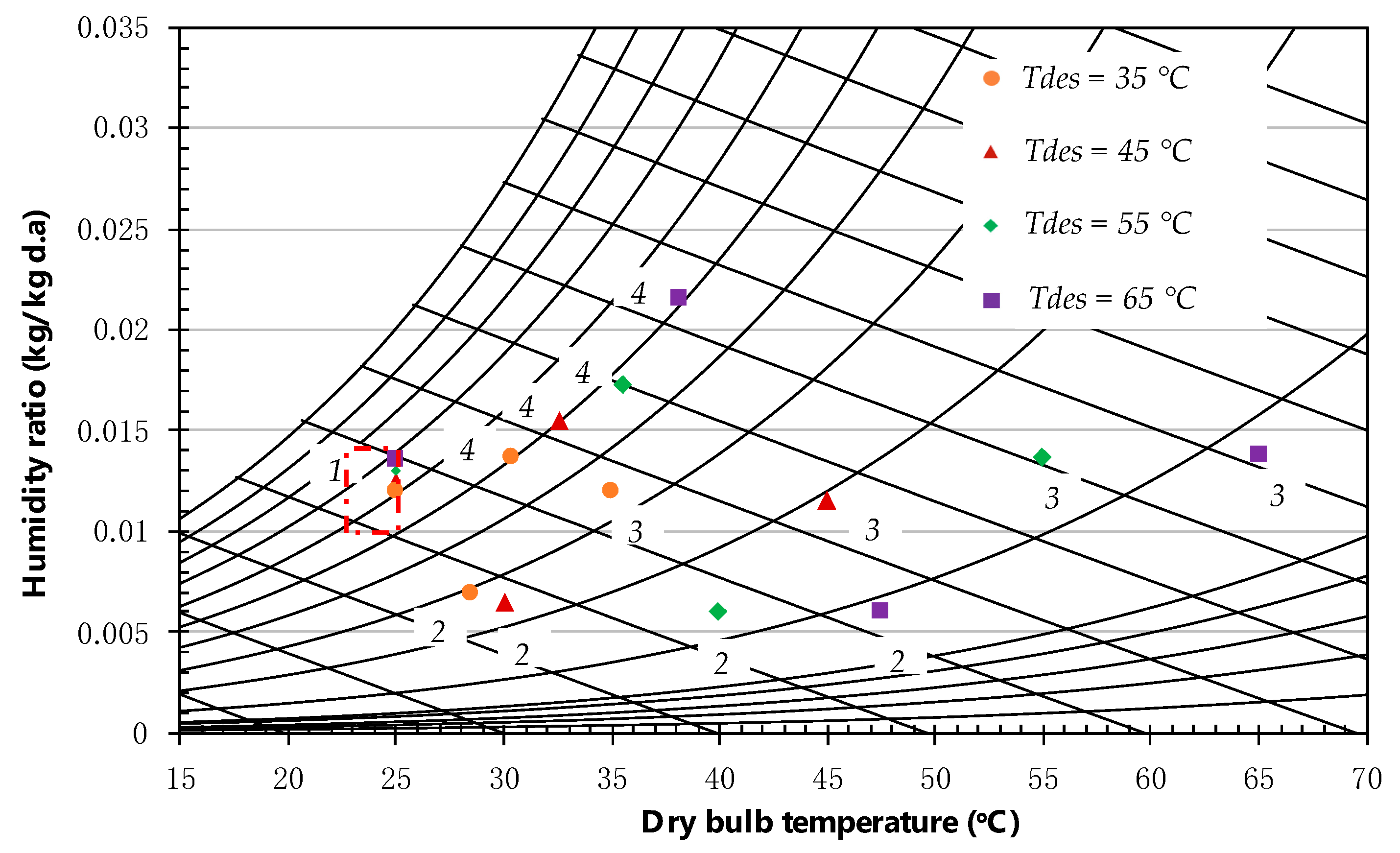
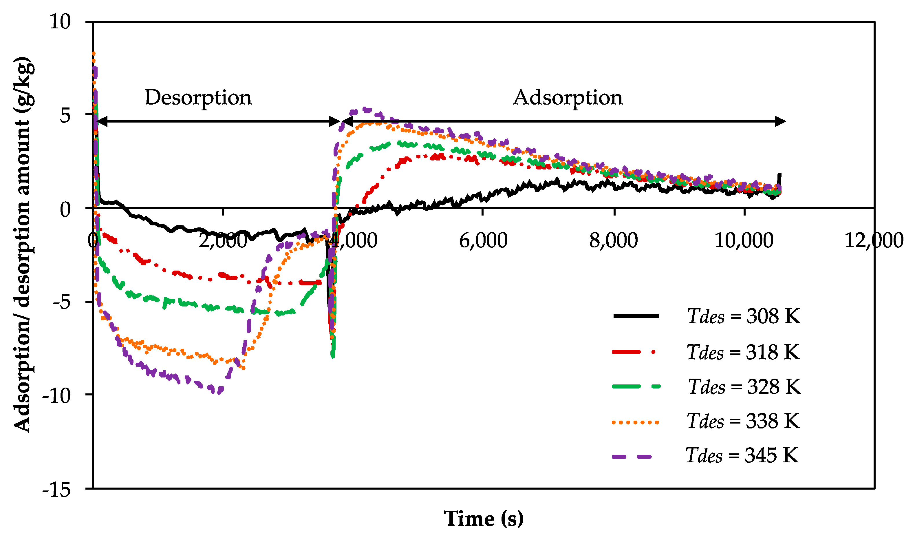
3.1. Influence of Desorption Temperature on the Water Content Removal

The effect of the adjusted adsorption temperature of 308, 318, 328, 338, and 345 K on the water content removal is shown in Figure 3. The recent experiment revealed that the water content removal (adsorption/desorption amount) increased with increasing of desorption air temperature. The ability of air to hold the water vapor improves as its temperature increases [39]. Consequently, as proven by Equations (2) and (3), the humidity ratio of the outlet air rose, resulting in higher differences between the humidity ratio between the inlet and outlet. Further, the water content removal during the adsorption/desorption processes tended to increase. Figure 3 also implies that the rate of adsorption and desorption decreased with the increase of time. In the desorption process, the water content removal increased rapidly, then decreased when the saturation pressure of the process air and the surface of the material became equilibrium. The reason behind this behavior was that at the beginning of the desorption process, the desiccant material was cooled, and the humidity content was high. Introducing hot and dry airstream into the cool desiccant material revealed high moisture adsorption in the beginning up to a particular time. After that, the gradient of moisture adsorption changed its direction, which indicated the conditions nearly reached saturaturation. For the case of adsorption, the behavior was slightly different from that of the desorption phase. At the beginning of the process, the water content removal was quite high, then gradually decreased and became steady. For all cases, the adsorption process finished in a similar point because the adsorption temperature and switching time remained unchanged during the process.
There was a different behavior observed on the desorption side when the temperature increased to the values of 338 and 345 K, as indicates in Figure 3. At a high desorption temperature of more than 338 K, the desorption phase was completed earlier than the other variation. This behavior was caused by the water-vapor sorption kinetics properties of the polymer adsorbent. At high desorption temperature, the water vapor sorption kinetics is high [40], leading to a decrease in the time required for the desorption phase. It implies that the desorption rate at a high temperature is faster, as compared to the low temperature. Additionally, the behavior of the rate of adsorption material, when exposed to high temperatures, can be explained by the mechanism of water vapor adsorbed into the polymer. It followed the Arrhenius equation, where the adsorption rate is dependent on temperature and activation energy. In high desorption temperatures, the molecular motions are easier; therefore, they show rapid uptake as compared to the low desorption temperature [41]. The high temperature leads to the quicker release of water vapor. The results show that the values of adsorption/desorption amount increased from 5, 5.4, 5.8, 7.4, and 7.9 g/kg, respectively, for desorption temperatures (Tdes) of 308, 318, 328, 338, and 345 K.

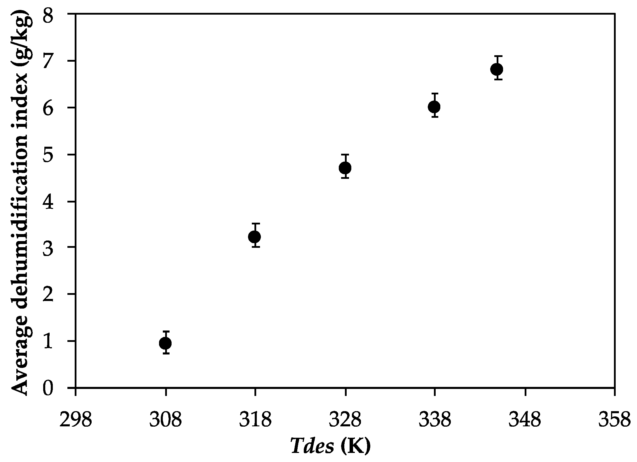
3.2. Influence of Desorption Temperature on Dehumidification Index

Figure 4 shows the variation of the dehumidification index under different desorption temperatures. It suggests that in enhancing the desorption temperature, the average dehumidification index has a tendency to increase, mainly due to the effect of the humidity ratio [30]. The important key of the dehumidification process is the rate of the water vapor adsorbed, which is a function of the mass transfer. This mass transfer is driven by the partial pressure of water vapor and its saturation pressure. High vapor pressure at the elevated temperature guiding to more mass transfer occurs. Accordingly, the high moisture content in the air provides a high driving force for moisture transport; hence, it increases the dehumidification index. When increasing desorption temperatures from 308, 318, 238, 338, and 345 K, the average dehumidification indexes increased from 1, 3, 5, 6, and 6.8 g/kg, respectively.

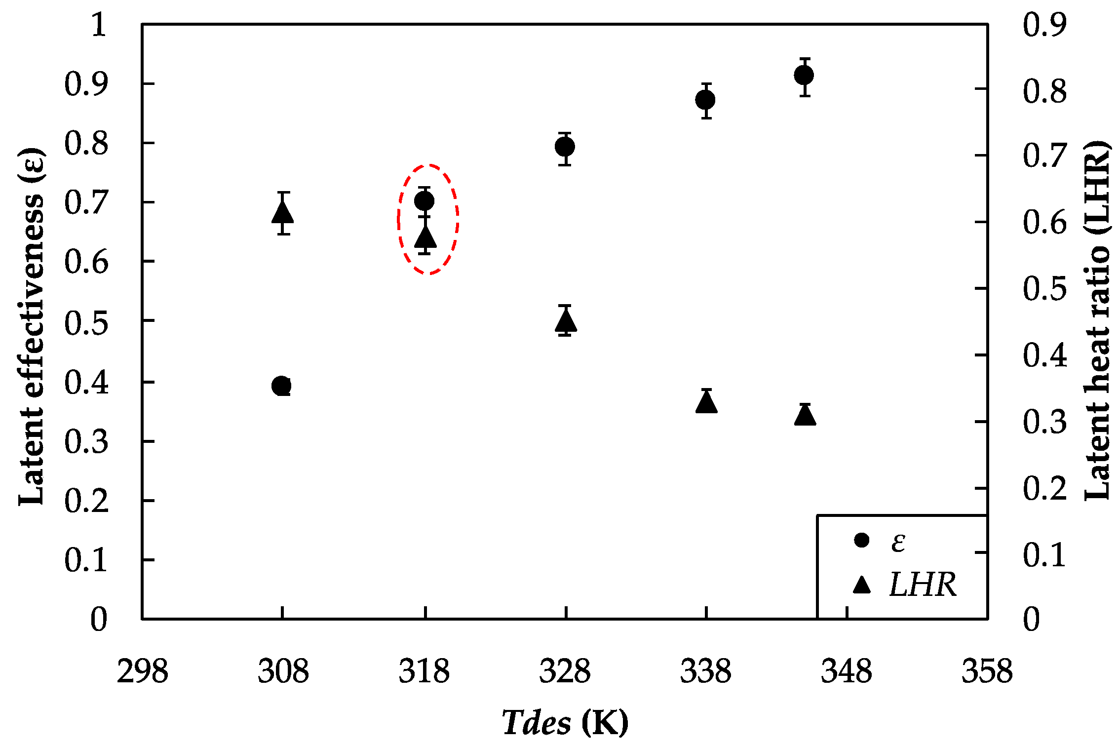
3.3. The Effect of Latent Heat on the Performance of the System

The latent heat effect into the performance of the system was assessed on the basis of the latent heat effectiveness and latent heat ratio (LHR). Figure 5 shows the impact of the latent heat on the performance of the system under different desorption temperatures.
The latent heat ratio and effectiveness showed different characteristics towards the variation of desorption temperatures. It was shown that the increase of desorption temperature reduced the latent heat ratio; contrarily, it increased the latent heat effectiveness. The increment of latent heat effectiveness due to the increase of the desorption temperature is also consistent with the results found in the existing literature [42]. In association with the average dehumidification index in Figure 4, particularly on high temperature, the desiccant dehumidification systems could provide a large difference of water vapor adsorption between the adsorption and desorption processes. However, to achieve a high temperature, a high amount of energy input was required. Energy input was employed to reach a high desorption temperature to heat the polymer. Thus, the polymer became dry and could adsorb more moisture for the dehumidification process. Energy consumption to achieve a high temperature directly influenced the total heat required for the desiccant dehumidification system. Increasing the desorption temperature guided the increase of sensible heat, therefore reducing the latent heat ratio. For the case of latent effectiveness, at high desorption temperature, the sorption capacity was higher because the humidity of the hot air is lower. Thus, enhancing the moisture uptake was followed by increasing the latent effectiveness. On the basis of the results, we found that if we considered energy saving, the desorption temperature should be low in order to achieve high performance of the system. In contrast, if attention was given to the moisture removal ability, the high desorption temperature was necessary.
However, Figure 5 indicates, in the form of a circle, a recommendation parameter for optimizing the system performance. We found that a suitable desorption temperature was 318 K for the desiccant dehumidification system. It showed that the latent effectiveness and latent heat ratio almost reached a similar value. In this case, the heat requirement for dehumidification was almost equal to the ability of moisture removal. Moreover, the results of the present study established that when the desorption temperatures increased from 308, 318, 328, 338, and 345 K, the latent heat ratios decreased from 0.61, 0.58, 0.45, 0.33, and 0.31 respectively, whereas the latent effectiveness increased from 0.39, 0.7, 0.79, 0.87 and 0.91, when the desorption temperature increased from 308, 318, 328, 338, and 345 K, respectively.

3.4. Energy Analysis

The total electricity cost of a dehumidification system can be calculated by considering the dehumidification load and the required energy to drive the process air (i.e., for the fan). A simple process of a dehumidification system including the dehumidification and regeneration processes is represented by Figure 6.
As shown in Figure 6, the energy resources for the regeneration process opens a contribution to renewable energy and industrial waste heat. The required total electricity can be reduced somehow by coupling the dehumidification system with the solar thermal energy to elevate the temperature of regeneration. The process inside the dehumidification system is altered continuously from adsorption and desorption. Within the study, as also mentioned in Section 4, the proper desorption temperature for the current system was 318 K. Therefore, the analysis of energy cost was based on the properties of the current system under 318 K.
The total energy demand can be calculated as the total of electricity for dehumidifying the air (Qlat), regenerating the material (Qsen), and circulating the air by using a fan (Wfan). The total energy demand (Et) is given as
E t = Q l a t + Q s e n + W f a n
and
W f a n = V ˙ a P a i r ε f a n
where V ˙ a , P a i r , and ε f a n denote the volume flow rate (m3/s), pressure drop (Pa), and efficiency of the fan (%), respectively. The assumption of the efficiency of the fan was considered at the value of 70% [43]. Then, the electricity of the fan was found to be 0.15 kW. On the basis of the experimental results, the total energy demand was found in the value of 0.624 kWh. The calculation of the cost mainly depends on the supply price of electricity in each country. In the case of the standalone dehumidification system, the current system consumed less energy when compared to conventional air conditioning. However, the initial cost for the desiccant dehumidification system might be higher than the conventional one. The benefit can cover this drawback in that the energy-saving from the standalone dehumidification system is able to lower the operational cost of the system [44].

4. Conclusions

The effect of the latent heat on the performance of the desiccant dehumidification system in terms of latent heat effectiveness and latent heat ratio through five different desorption temperatures of 308, 318, 328, 338, and 345 K were experimentally examined. It was revealed that the highest latent effectiveness and dehumidification ability were found at the highest desorption temperature of 345 K, at 0.91 and 6.8 g/kg, respectively. The maximum latent heat ratio was obtained when the system was driven by the low desorption temperature of 308 K. We clarified that even though the system was driven by a low desorption temperature, it could nonetheless give a good mositure removal performance with a high latent heat ratio. An effective dehumidification system is intended for giving a high latent amount of heat, which shows that the system has high dehumidification capacity. Moreover, it also implies that the higher the ratio between the latent heat and sensible heat, the greater the effectiveness of the desiccant dehumidification system.

Author Contributions

Conceptualization, I.Y. and T.M.; Formal analysis, I.Y.; Investigation, I.Y.; Supervision, K.T. and T.M.; Validation, T.M.; Writing-original draft, I.Y.; Writing-review & editing, A.T.W., K.T. and T.M. All authors have read and agreed to the published version of the manuscript.

Funding

This study was supported by Japan Society for the Promotion of Science (JSPS) Bilateral Programs Joint Research Project with Directorate General of Resources for Science, Technology and Higher Education, the Ministry of Research, Technology, and Higher Education of the Republic of Indonesia (DG-RSTHE) 2018-2020.

Acknowledgments

The first author wishes to thank the Ministry of Research, Technology, and Higher Education (RISTEKDIKTI) and the Ministry of Finance, Indonesia, Endowment Fund for Education (LPDP) of the Republic of Indonesia for their support of this study within the framework of Beasiswa Unggulan Dosen Indonesia–Luar Negeri (BUDI-LN).

Conflicts of Interest

The authors declare no conflict of interest.

Nomenclature

Aadsorption potential (kJ/kg)
cpspecific heat capacity (J/kg·K)
cp,bspecific heat capacity of the bed (kJ/kg·K)
dmoisture removal capacity (kg/kg)
Dhhydraulic diameter of the air channel (m)
Didehumidification index (kg/kg)
Eadsorption characteristics parameter (kJ/kg)
Ettotal energy demand (W)
hchannel height (air layer)
Hdesiccant block height (m)
kdthermal conductivity of sorbent (W/m·K)
Ldesiccant block length (m)
LHRlatent heat ratio
nfitting constant
pfin spacing (m)
Ppartial pressure (kPa)
Posaturation pressure (kPa)
Qadsaverage of enthalpy exchange in adsorption process (W)
Qdesaverage of heat exchange in the desorption process (W)
Qlatlatent heat transfer (W)
Qsensensible heat transfer (W)
rradius of the adsorption particle (m)
Rspecific gas constant for water (kJ/kg·K)
tdehumidification time (s)
Ttemperature (K)
ReReynolds number
RHrelative humidity (%)
Uaair velocity (m/s)
wdesiccant block width (m)
V ˙ a ,volume flow rate (m3/s)
Wequilibrium adsorption uptake (kg/kg)
Wfanelectricity for fan (W)
Womaximum adsorption capacity (kg/kg)
Xhumidity ratio (kg/kg)
Xidealideal humidity ratio of air stream at the outlet of dehumidification system (kg/kg)
Hheat of adsorption (kJ/kg)
Greek symbol
εlatent heat effectiveness
εfanefficiency of the fan (%)
δsorbent thickness (m)
γlatent heat of vaporization (kJ/s)
μdynamic viscosity of the air (kg/m.s)
ρaair density (kg/m3)
ρbbed density (kg/m3)
ϕporosity
Subscript
adsadsorption
desdesorption
ininlet
outoutlet

References

  1. Al-Homoud, M.S. Optimum Thermal Design of Air-Conditioned Residential Buildings. Build Environ. 1997, 32, 203–210. [Google Scholar] [CrossRef]
  2. Zhang, J.Y.; Ge, T.S.; Dai, Y.J.; Zhao, Y.; Wang, R.Z. Experimental Investigation on Solar Powered Desiccant Coated Heat Exchanger Humidification Air Conditioning System in Winter. Energy J. 2017, 137, 468–478. [Google Scholar] [CrossRef]
  3. Zhou, Y.P.; Wu, J.Y.; Wang, R.Z.; Shiochi, S. Energy Simulation in the Variable Refrigerant Flow Air-conditioning System under Cooling Conditions. Energ. Build. 2007, 39, 212–220. [Google Scholar] [CrossRef]
  4. Mohhamadi, S.M.H.; Ameri, M. Energy and Exergy Comparison of a Cascade Air Conditioning System using Different Cooling Strategies. Int. J. Refrig. 2014, 41, 14–26. [Google Scholar] [CrossRef]
  5. Fermanel, F.; Miriel, J. Air Heating System: Influence of a Humidifier on Thermal Comfort. Appl. Therm. Eng. 1999, 19, 1107–1127. [Google Scholar] [CrossRef]
  6. Antonellis, S.D.; Intini, M.; Joppolo, C.M.; Molinaroli, L.; Romano, F. Desiccant wheels for air humidification: An Experimental and Numerical Analysis. Energy Convers. Manag. 2015, 106, 355–364. [Google Scholar] [CrossRef]
  7. Kaseminejad, H. Analysis of One-dimensional Fin Assembly Heat Transfer with Dehumidification. Int. J. Heat Mass Transf. 1995, 38, 445–462. [Google Scholar] [CrossRef]
  8. Su, W.; Zhang, X. Thermodynamics Analysis of a Compression-absorption Refrigeration Air-conditioning System Coupled with Liquid Desiccant Dehumidification. Appl. Therm. Eng. 2017, 115, 575–585. [Google Scholar] [CrossRef]
  9. Yaningsih, I.; Wijayanta, A.T.; Miyazaki, T.; Koyama, S. Analysis of heat and mass transfer characteristics of desiccant dehumidifier system with honeycomb configuration. Appl. Therm. Eng. 2018, 144, 658–669. [Google Scholar] [CrossRef]
  10. Zhang, L.Z. Progress on Heat and Moisture Recovery with Membranes: From Fundamentals to Engineering Applications. Energy Convers. Manag. 2012, 63, 173–195. [Google Scholar]
  11. Miyazaki, T.; Akisawa, A.; Nikai, I. The Cooling Performance of a Building Integrated Evaporative Cooling System Driven by Solar Energy. Energ. Build. 2011, 43, 2211–2218. [Google Scholar] [CrossRef]
  12. Wrobel, J.; Walter, P.S.; Schmitz, G. Performance of a Solar Assisted Air Conditioning System at Different Locations. Sol. Energy 2013, 92, 69–83. [Google Scholar] [CrossRef]
  13. Benhammou, M.; Draoui, B.; Zerrouki, M.; Marif, Y. Performance Analysis of an Earth-to-air exchanger Assisted by a Wind Tower for Passive Cooling of Buildings in Arid and Hot Climate. Energy Convers. Manag. 2015, 91, 1–11. [Google Scholar] [CrossRef]
  14. Daher, N.A.; Raoofat, M.; Saad, M.; Mougharbel, I.; Asber, D.; Beltran-Galindo, J. Improve the HVAC Contribution in Wind Power Smoothing. Electr. Pow. Syst. Res. 2017, 171, 219–229. [Google Scholar] [CrossRef]
  15. Garimella, S.; Brown, A.M.; Nagavapura, A.K. Waste Heat Driven Absorption/vapor-compression Cascade Refrigeration System for Megawatt Scale, High-flux, Low-temperature Cooling. Int. J. Refrig. 2011, 34, 1776–1785. [Google Scholar] [CrossRef]
  16. Ali, S.M.; Chakraborty, A. Thermodynamic Modelling and Performance Study of an Engine Waste Heat Driven Adsorption Cooling for Automotive Air-conditioning. Appl. Therm. Eng. 2015, 90, 54–63. [Google Scholar] [CrossRef]
  17. Ling, J.; Kuwabara, O.; Hwang, Y.; Radermacher, R. Enhancement Options for Separate Sensible and Latent Cooling Air-conditioning Systems. Int. J. Refrig. 2013, 36, 45–57. [Google Scholar] [CrossRef]
  18. Tso, C.Y.; Chao, C.Y.H. Activated Carbon, Silica-gel, Calcium Chloride Composite Adsorbents for Energy Efficient Solar Adsorption Cooling and Dehumidification Systems. Int. J. Refrig. 2012, 35, 1626–1638. [Google Scholar] [CrossRef]
  19. Sultan, M.; Miyazaki, T.; Koyama, S. Optimization of Adsorption Isotherm Types for Desiccant Air-Conditioning Applications. Renew. Energ. 2018, 121, 441–450. [Google Scholar] [CrossRef]
  20. Aristov, Y.I. Challenging offers of Material Science for Adsorption Heat Transformation: A Review. Appl. Therm. Eng. 2013, 50, 1610–1618. [Google Scholar] [CrossRef]
  21. Enteria, N.; Yoshino, H.; Takaki, H.; Mochida, A.; Satake, A.; Yoshie, R. Effect of the Regeneration Temperature in the Exergetic Performances of the Develop Desiccant-Evaporative Air-Conditioning System. Int. J. Refrig. 2013, 36, 2323–2342. [Google Scholar] [CrossRef]
  22. Chen, Y.; Yin, Y.; Zhang, X. Performance Analysis of a Hybrid Air-Conditioning System Dehumidified by Liquid Desiccant with Low Temperature and Low Concentration. Energ. Build. 2014, 77, 91–102. [Google Scholar] [CrossRef]
  23. Jia, C.X.; Dai, Y.J.; Wu, J.Y.; Wang, R.Z. Experimental Comparison of Two Honeycombed Desiccant Wheels Fabricated with Silica Gel and Composite Desiccant Material. Energy Convers. Manag. 2006, 47, 2523–2534. [Google Scholar] [CrossRef]
  24. Angrisani, G.; Roselli, C.; Sasso, M. Experimental Assessment of The Energy Performance of a Hybrid Desiccant Cooling System and Comparison with other Air-conditioning Technologies. Appl. Energy 2015, 138, 533–545. [Google Scholar] [CrossRef]
  25. Lu, S.M.; Shyu, R.J.; Yan, W.J.; Chung, T.W. Development and Experimental Validation of Two Novel Solar Desiccant—Dehumidification-Regeneration Systems. Energy J. 1995, 20, 751–757. [Google Scholar] [CrossRef]
  26. Oliveira, A.C.; Afonso, C.F.; Riffat, S.B.; Doherty, P.S. Thermal Performance of a Novel Air Conditioning System using a Liquid Desiccant. Appl. Therm. Eng. 2000, 20, 1213–1223. [Google Scholar] [CrossRef]
  27. Kanoğlu, M.; Bolattürk, A.; Altuntop, N. Effect of Ambient Conditions on the First and Second Law Performance of an Open Desiccant Cooling Process. Renew. Energy 2007, 32, 931–946. [Google Scholar] [CrossRef]
  28. Jeong, J.; Yamaguchi, S.; Saito, K.; Kawai, S. Performance Analysis of Desiccant Dehumidification Systems Driven by Low-grade Heat Source. Int. J. Refrig. 2011, 34, 928–945. [Google Scholar] [CrossRef]
  29. Panaras, G.; Mathioulakis, E.; Belessiotis, V. Solid Desiccant Air-conditioning Systems-Design Parameters. Energy J. 2011, 36, 2399–2406. [Google Scholar] [CrossRef]
  30. Ge, T.S.; Dai, Y.J.; Wang, R.Z.; Li, Y. Performance of Two-stage Rotary Desiccant Cooling System with Different Regeneration Temperatures. Energy J. 2015, 80, 556–566. [Google Scholar] [CrossRef]
  31. Lee, H.; Lin, X.; Hwang, Y.; Radermacher, R. Performance Investigation on Solid Desiccant Assisted Mobile Air Conditioning System. Appl. Therm. Eng. 2016, 103, 1370–1380. [Google Scholar] [CrossRef]
  32. Lock, G.S.H. Latent Heat Transfer: An Introduction to Fundamentals; Oxford University Press: New York, NY, USA, 1994. [Google Scholar]
  33. Chung, J.D.; Lee, D.; Yoon, S.M. Optimization of Desiccant Wheel Speed and Area Ratio of Regeneration to Dehumidification as a Function of Regeneration Temperature. Sol. Energy 2009, 83, 625–635. [Google Scholar] [CrossRef]
  34. Datta, N.; Chakraborty, A.; Ali, S.M.; Choo, F.H. Experimental Investigation od Multi-effect Regenerator for Desiccant Dehumidifier: Effects of Various Regeneration Temperatures and Solution Flow Rates on System Performances. Int. J. Refrig. 2017, 76, 7–18. [Google Scholar] [CrossRef]
  35. Ruivo, C.R.; Goldsworthy, M.; Intini, M. Interpolation Methods to Predict the Influence of Inlet Airflow States on Desiccant Wheel Performance at Low Regeneration Temperature. Energy J. 2014, 68, 765–772. [Google Scholar] [CrossRef]
  36. Mandegari, M.A.; Pahlavanzadeh, H. Introduction of a New Definition for Effectiveness of Desiccant Wheels. Energy J. 2009, 34, 797–803. [Google Scholar] [CrossRef]
  37. Islam, M.R.; Alan, S.W.L.; Chua, K.J. Studying the Heat and Mass Transfer Process of Liquid Desiccant for Dehumidification and Cooling. Appl. Energy 2018, 221, 334–347. [Google Scholar]
  38. Kirkup, L.; Frenkel, B. An Introduction to Uncertainty in Measurement; Cambridge University Press: New York, NY, USA, 2006. [Google Scholar]
  39. Amer, E.H.; Kotb, H.; Mostafa, G.H.; El-Ghalban, A.R. Theoretical and Experimental Investigation of Humidification-dehumidification Desalination Unit. Desalination 2009, 249, 949–959. [Google Scholar] [CrossRef]
  40. Sultan, M.; El-Sharkawy, I.I.; Miyazaki, T.; Saha, B.B.; Koyama, S.; Maruyama, T.; Maeda, S.; Nakamura, T. Water Vapor Sorption Kinetics of Polymer-Based Sorbent: Theory and Experiments. Appl. Therm. Eng. 2016, 106, 192–202. [Google Scholar] [CrossRef]
  41. Simavilla, D.N.; Huang, W.; Vanderstrick, P.; Ryckaert, J.P.; Sferrazza, M.; Napolitano, S. Mechanism of Polymer Adsorption onto Solid Substrate. ACS Macro Lett. 2017, 6, 975–979. [Google Scholar] [CrossRef]
  42. Chung, J.D.; Lee, D. Effect of desiccant isotherm on the performance of the desiccant wheel. Int. J. Refrig. 2009, 32, 720–726. [Google Scholar] [CrossRef]
  43. Schild, P.G.; Mysen, M. Recommendation on Spesific Fan Power and Fan System Efficiency; AIVC Technical Note 65; Air Infiltration and Ventilation Centre: Sint-Stevens-Woluwe, Belgium, 2009. [Google Scholar]
  44. Subiantoro, A. Feasibility Analysis of the Hybrid Dehumidifier-air conditioner technology for small-scale household applications in the tropis. Sci. Technol. Built Environ. 2019, 25, 177–188. [Google Scholar] [CrossRef]
Figure 1. (a) The photograph [9]; (b) schematic diagram of the desiccant dehumidification system; (c) structure of the polymer desiccant block.
Applsci 10 00868 g001
Figure 2. Psychrometric chart of the current experimental point. Tdes: desorption temperatures.
Applsci 10 00868 g002
Figure 3. Water content removal during adsorption/desorption processes for different desorption temperatures.
Applsci 10 00868 g003
Figure 4. The influence of the desorption temperature on the dehumidification index.
Applsci 10 00868 g004
Figure 5. Latent heat effect on the performance of the system under various desorption temperatures.
Applsci 10 00868 g005
Figure 6. The simple process inside the desiccant dehumidification system.
Applsci 10 00868 g006
Table 1. Parameters of polymer honeycomb desiccant structure [9].
ParameterSymbolValueUnit
Widthw0.2m
LengthL0.2m
HeightH0.2m
Thickness of sorbentδ3 × 10⁻⁴m
Channel height (air layer)h1.7 × 10−3 m
Fin spacingp3.6 × 10−3m
Heat of adsorptionΔH2500kJ/kg
Densityρb1500kg/m3
Specific heat capacity of the bedcp,b805kJ/kg·K
Thermal conductivity of sorbentkd0.33W/m·K
Porosity ϕ0.9-
Radius of the adsorbent particler1.29 × 10−6m
Table 2. Experimental conditions of the desiccant dehumidification system. Tin: Temperature inlet, Xin: Humidity ratio inlet, RHin: Relative humidity inlet, Ua: air velocity, Re: Reynolds number.
ProcessParameters
Tin (K)Xin (g/kg)RHin (%)Ua (m/s)Re
Desorption30812.235.230.16447.6
31811.520.190.16526.6
32813.715.50.16593.7
33813.89.100.15701.9
34513.56.630.15712.7
Adsorption2939.260.250.16304.4
Table 3. Uncertainty analysis.
ParameterSymbolValue
Humidity ratioX2.37%
Dehumidification index Di4.61%
Latent effectivenessε4.8%
Latent heat ratioLHR5.31%
Reynolds numberRe3.72%

