Article

Compression Shear Properties of Bonded–Bolted Hybrid Single-Lap Joints of C/C Composites at High Temperature

1
National Key Laboratory of Science and Technology on Advanced Composites in Special Environments, Harbin Institute of Technology, Harbin 150000, China
2
Beijing Institute of Near-space Vehicle’s System Engineering, Beijing 100076, China
*
Author to whom correspondence should be addressed.
Appl. Sci. 2020, 10(3), 1054; https://doi.org/10.3390/app10031054
Submission received: 13 December 2019 / Revised: 18 January 2020 / Accepted: 27 January 2020 / Published: 5 February 2020
(This article belongs to the Special Issue Progress of Fiber-Reinforced Composites: Design and Applications)

Abstract

:
Based on previous research, in this paper, the compressive shear failure behavior and mechanical properties of bonded–bolted hybrid single-lap joints of C/C composites at high temperature were studied. The compression shear test was performed on the joints at 800 °C to obtain the load–displacement curve and failure morphology. The failure modes of joints were observed by digital microscopy and scanning electron microscopy. A numerical analysis model was implemented in finite element code Abaqus/Explicit embedded with the user material subroutine (VUMAT). The numerical results were compared with the test results to verify the correctness of the model. The interrelationship of the compression shear loading mechanism and the variations in stress distribution between bonded joints and bonded–bolted hybrid joints at high temperature were explored. The progressive damage of hybrid joints and the variations in the ratio of the bolt load to the total load with displacement were obtained.

1. Introduction

The design of a composite connection structure is one of the difficulties in the research of composite application, and the bearing capacity of the joint directly affects the reliability of composite components. A great deal of research has been conducted on the mechanical properties of the conventional bonded [1,2,3,4,5,6] and bolted [7,8,9,10] joints of composite materials. Many adhesives undergo instantaneous brittle fracture when they fail, resulting in sudden damage to the structure. The bonded–bolted hybrid [11] connection has better security and integrity than a bonded and bolted connection. Although the hybrid connection has been used in aviation, shipbuilding, and many other industrial sectors [12,13], studies on composite hybrid joint structure design are lacking due to its complex force transmission mechanism. Most research [14,15,16,17,18] on hybrid joints has been limited to the tensile failure process of joints with a resin-based fiber-reinforced composite plate as an adherend and metal as a fastener at normal temperature, and the failure modes are usually adhesive fracture and hole extrusion failure. Failure analysis of joints in which both the adherend and fasteners [19,20] are high-temperature-resistant composites (C/C composites, high-temperature ceramics) under compression shear is rare. In addition to the complexity and high price of the preparation process [21] of highly temperature-resistant composites, these studies are rare due to the high brittleness, which makes the cutting and fine processing of specific shapes difficult, and damage to composites, which reduces their strength. Carbon-fiber-reinforced carbon (CFRC), or carbon-carbon [22,23], is a unique composite material consisting of carbon fibers embedded in a carbonaceous matrix. Originally developed for aerospace applications, its low density, high thermal conductivity, and excellent mechanical properties at elevated temperatures make it an ideal material for the automobile, ship, and aerospace industries [24,25,26,27,28]. Moreover, to improve the mechanical properties of the structure, it is essential to reduce the bending effect of single-lap joints due to eccentric loading and improve the shear bearing capacity of the adhesive, and there are few reports [29] on this aspect. Based on the research of [30], in this study, the failure modes and force transfer mechanism of C/C composites single-lap joints at 800 °C were obtained by means of tests and numerical simulation. The experimental results were compared with the calculated results to verify the correctness of the numerical model. The relationship of compression shear mechanical properties between the bonded joint and bonded–bolted hybrid joint at high temperature was determined.

2. Materials and Methods
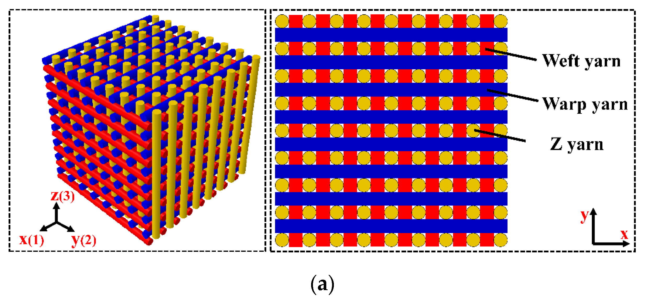
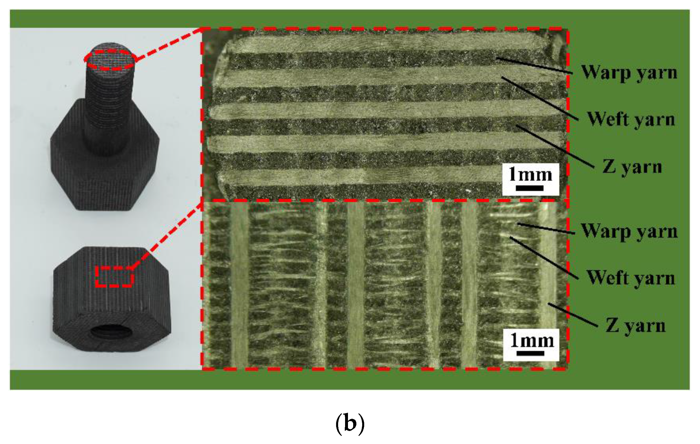
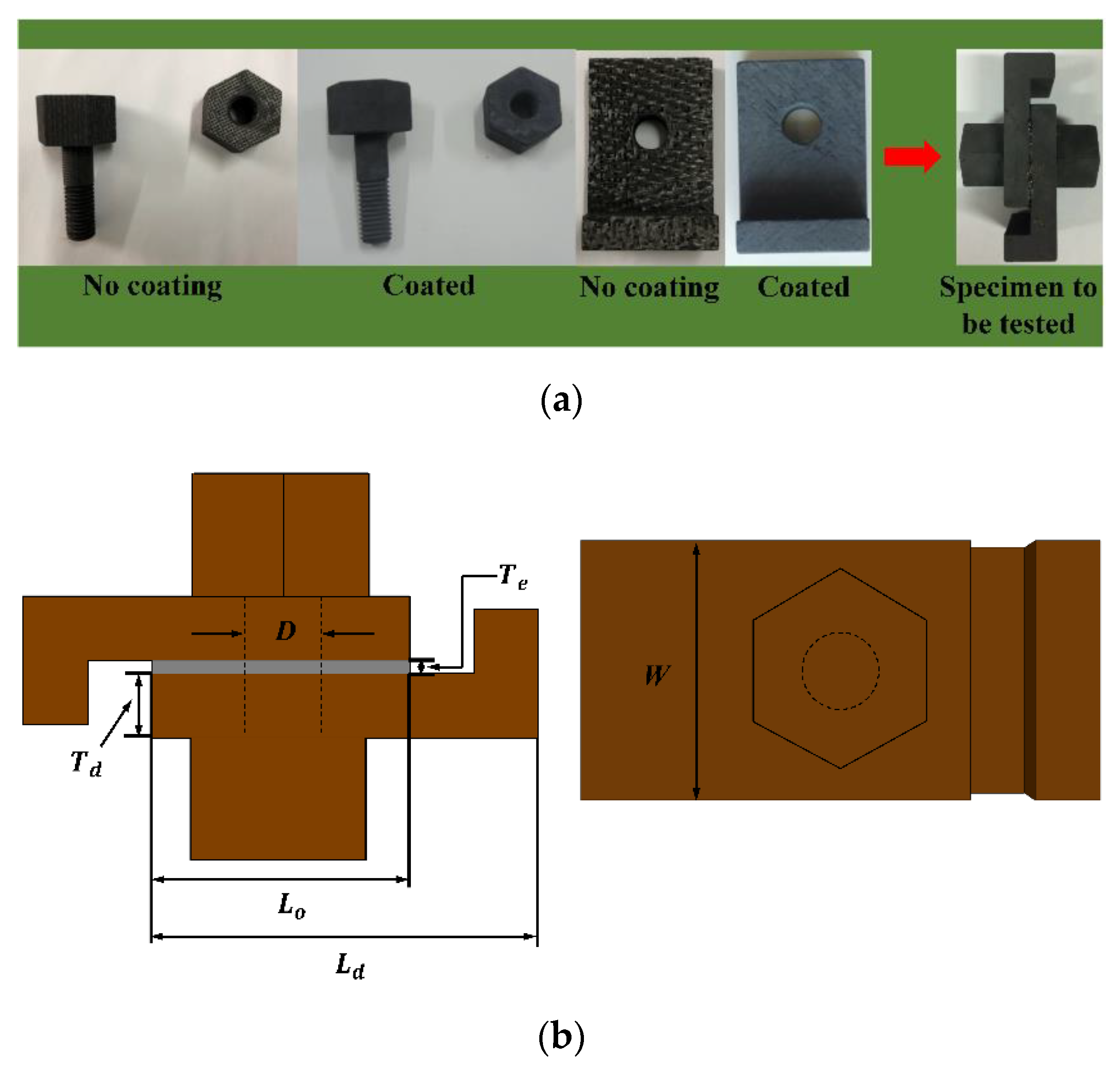
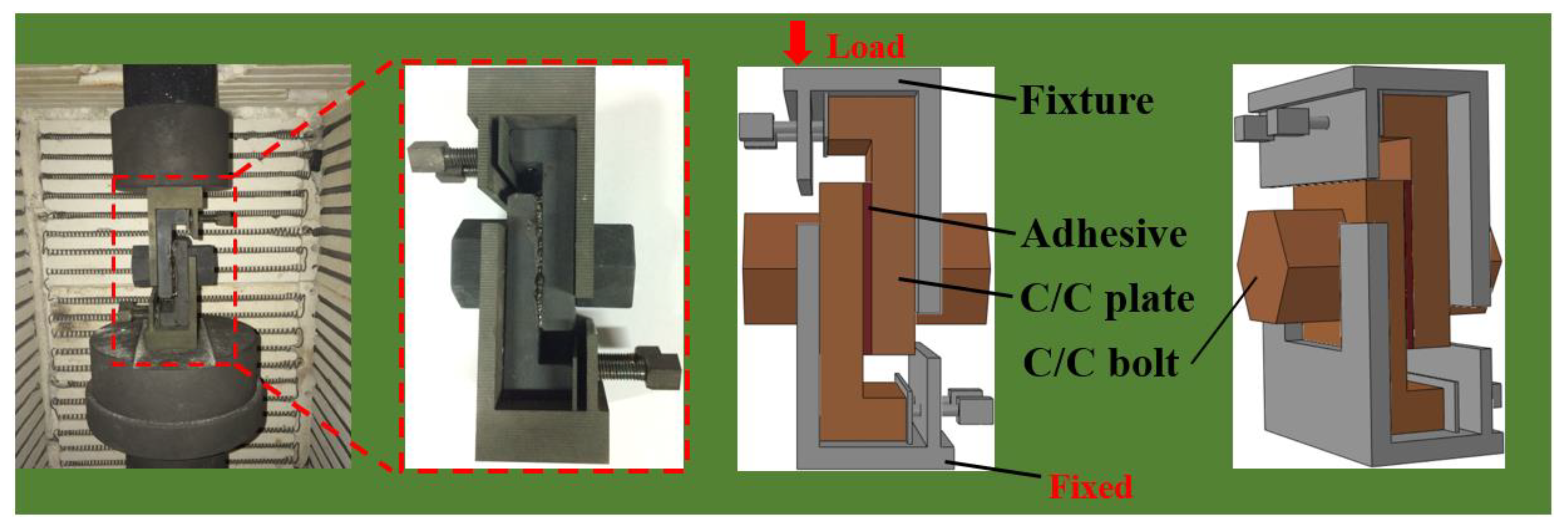
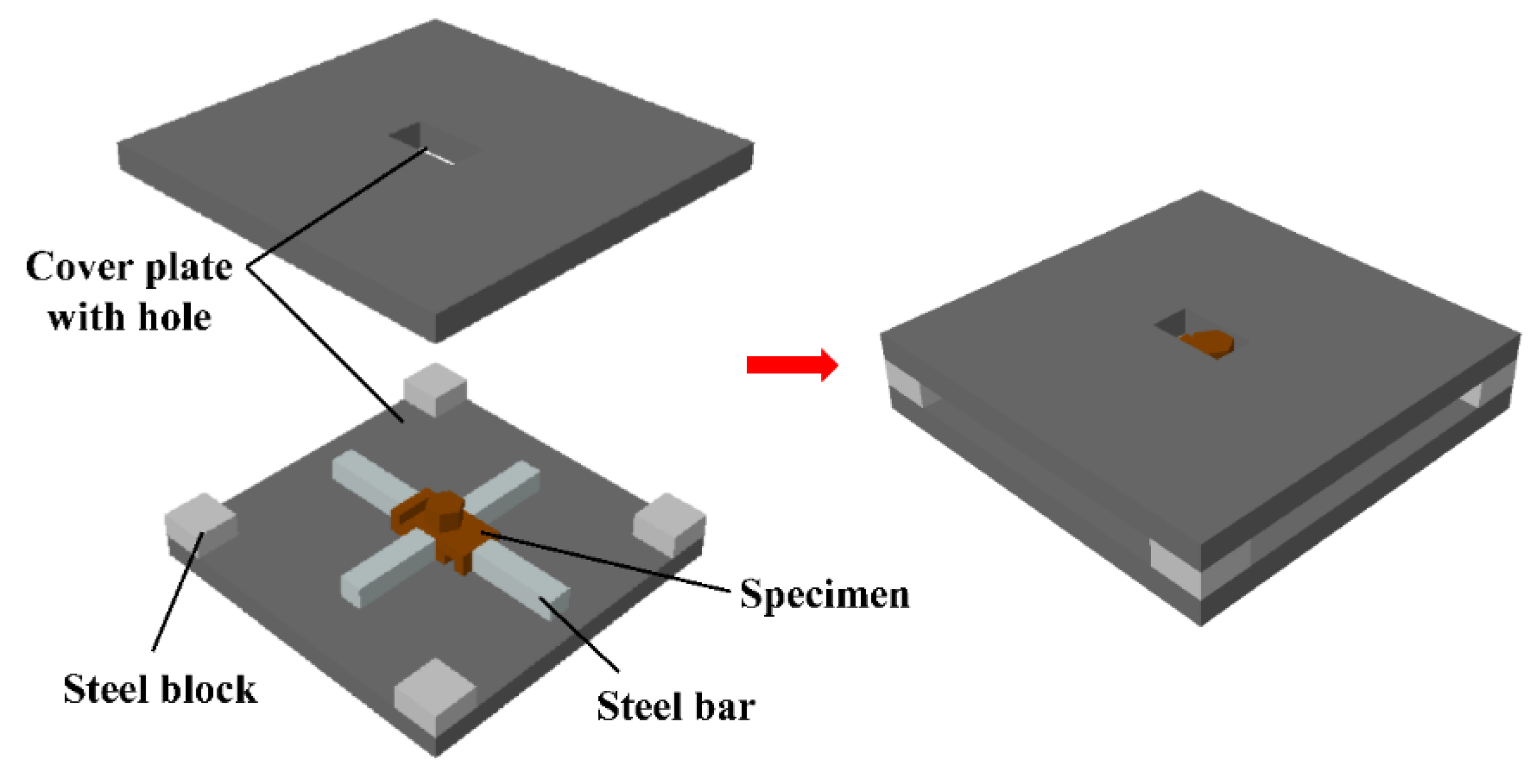
2.1. Experiment

The material of the adherend was C/C piercing woven composites used in [30]. The material of the bolt is C/C orthogonal three-directional woven composites. The x, y, and z correspond to three principal directions of the material, and the three directions are perpendicular T300-1k (Toray, Tokyo) carbon fibers. The preform weaving mode and fiber direction are shown in Figure 1a, and the microstructure of the fastener material observed by the digital microscopic system (VHX-7000, KEYENCE, Japan, Osaka) is shown in Figure 1b. The two kinds of preform were densified using the chemical vapor infiltration (CVI) and then graphitized to form C/C woven composites. To prevent the test piece from being damaged, chemical vapor deposition (CVD) was used to coat the surface of the adherend and fastener with a silicon carbide coating to obtain the antioxidant C/C composites required for the high-temperature test. The material performance of the adherend and fastener is shown in Table 1. The process parameters of CVI and CVD are listed in Table 2. The overlapped plate with a hole was shaped into the letter L. Two C/C plates and a bolt were assembled into one single-lap test piece. The prepared test piece and geometry dimensions are shown in Figure 2. The total length of the adherend (Ld) was 60 mm, the overlapping length (Lo) was 40 mm, the thickness of the adherend (Td) was 10 mm, the thickness of the adhesive (Te) was 0.2 mm, the width of the adherend (W) was 40 mm, and the bolt diameter D was 12 mm. Due to the high cost of C/C composites, three sets of test pieces were provided. In order to compare the bonded–bolted hybrid joint test results with the bonded joint test results at 800 °C in [30], in this study, the adhesive type, the adhesive curing method, the surface treatment method of test pieces, the testing equipment, and the fixture and loading method (Figure 3) were all completely consistent with that study. This study differed in that holes needed to be made in the center of the upper and lower cover plates to connect the adherend with the fasteners to control the adhesive thickness of the hybrid joint. In order to make the cured adhesive fill the bolt hole clearance, and to make the adhesive layer and bolt bear the load simultaneously during the test, holes in the adherend were drilled in advance, and the bolt was mounted before curing. The operation method is shown in Figure 4.

2.2. Finite Element Analysis

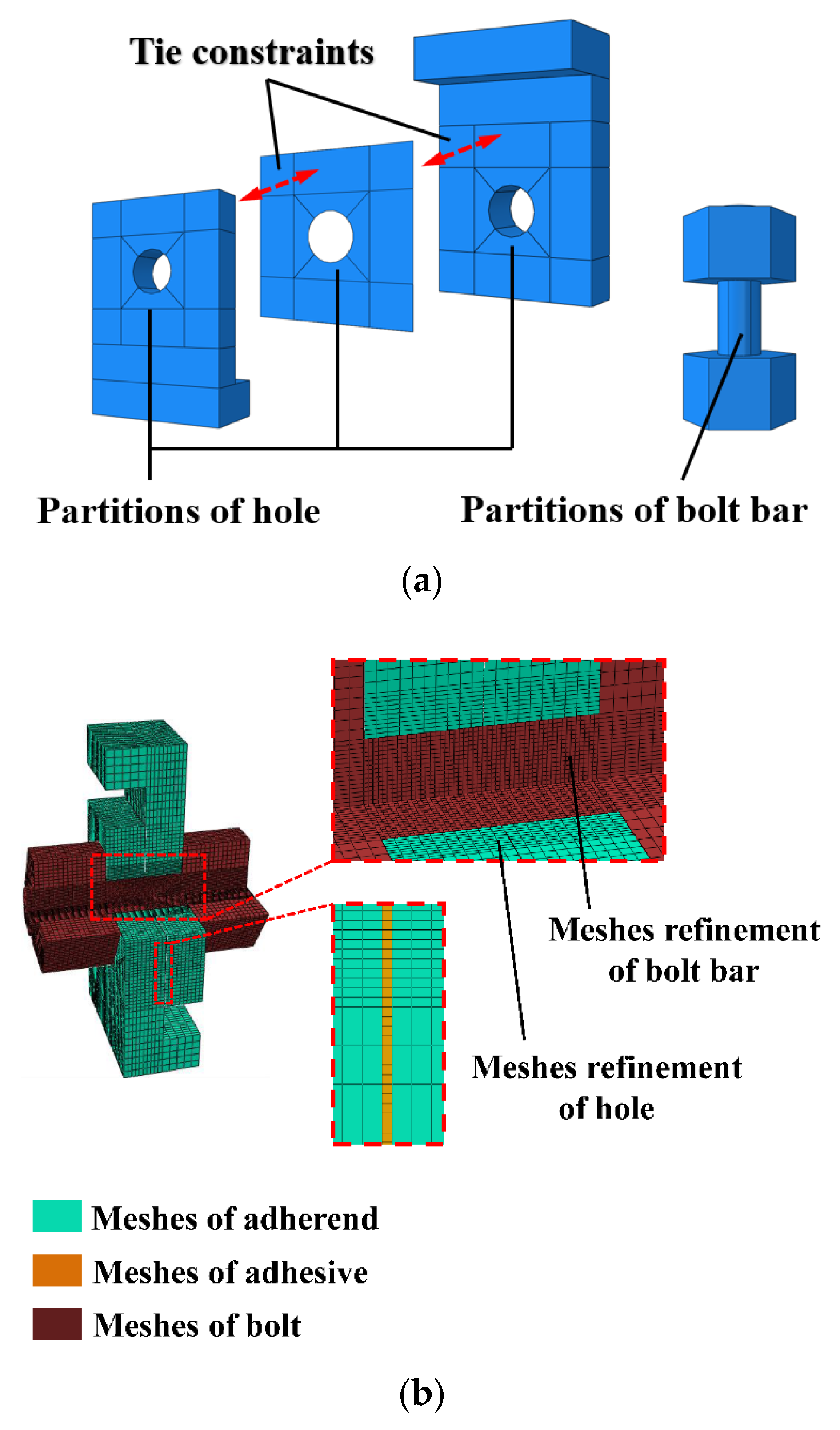
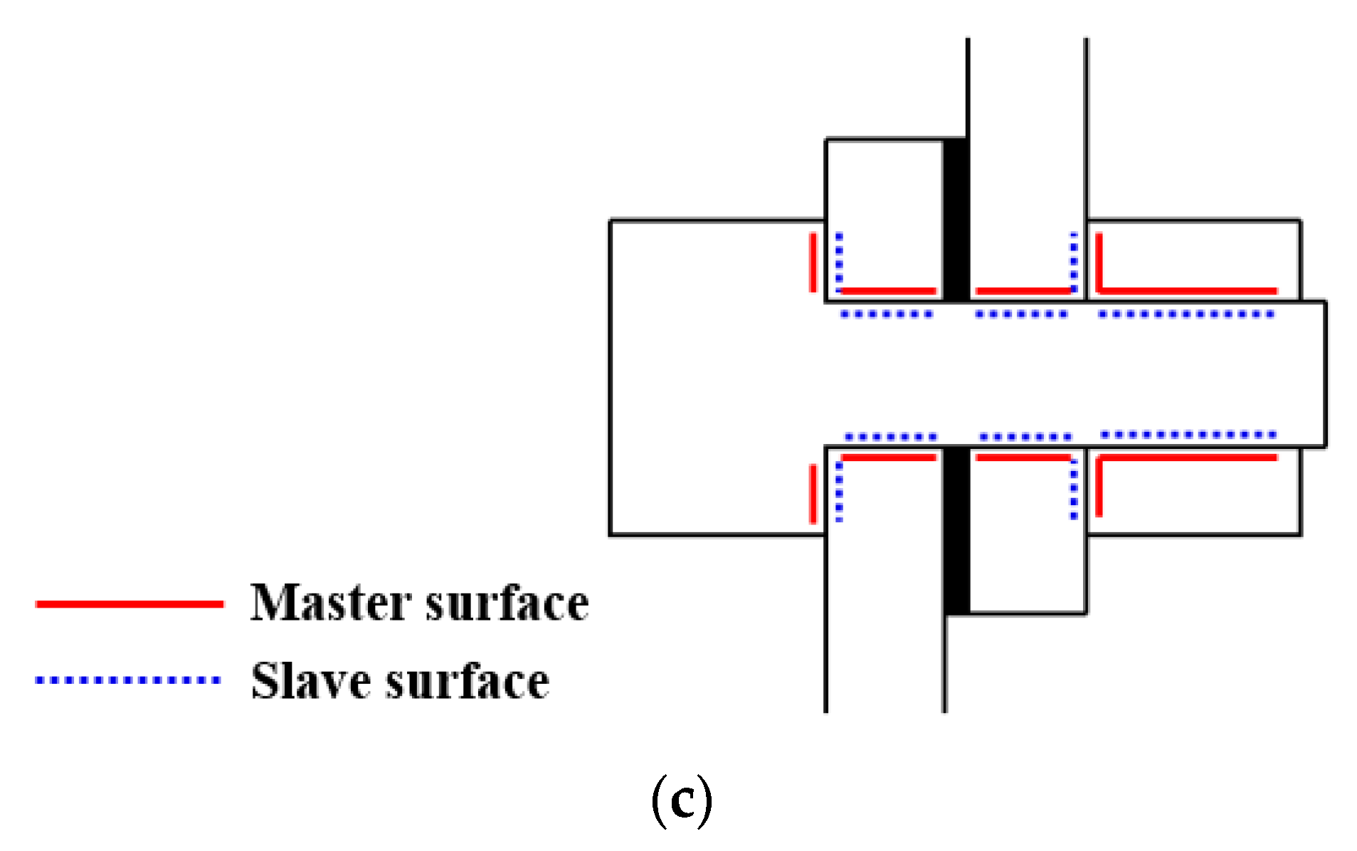
2.2.1. Model Establishment

For the above test process, the modeling was performed using ABAQUS 6.14 (Dassault, Paris, France,) finite element software. The bonded–bolted hybrid joint model consisted of four parts, including two lapped plates, an adhesive layer, and a bolt. A tie constraint existed between the lapped plates and the adhesive layer as shown in Figure 5a. Since the thread has little effect on the failure, the nut and screw were set as one part to speed up the calculation. To model the composites, an eight-node linear brick reduced integration element (C3D8R) was used. This element is suitable for simulating the three-dimensional loading process, and the calculation time is less than that of the quadratic element. In addition, it can reduce the hourglass problem and is not sensitive to element distortion [31]. For the adhesive layer, the same cohesive element as in [30] was adopted for modeling, and the element type was COH3D8R. As shown in Figure 5b, meshes of the adhesive layer, hole, and bolt rod were refined, respectively. The fixture slightly deformed during the loading and was set as a rigid body. The contacts in the model were achieved by defining contacting surfaces. The setting of the master and slave surfaces of the bolt and lapped plates is shown in Figure 5c. A finite slide was set between surfaces with a friction coefficient of 0.2 [32]. The hybrid joint contains two kinds of C/C composites and an adhesive layer, and the divergences of mechanical properties make the structure present rather complex mechanical behavior under load, coupled with the nonlinear contact between the bolt and the perforated plate and the adhesive layer. If an implicit analysis was adopted, the degradation and failure of the materials would easily lead to the non-convergence of the analysis, such that the calculation would stop before the maximum bearing capacity of the structure is reached. In this study, the ABAQUS/explicit module was used, the embedded user material subroutine VUMAT, combined with the Hashin [33] failure criterion and the stiffness degradation law of materials in [34]. Two analysis steps were set up throughout the loading process. Firstly, a temperature load was applied to the model using a predefined field. The initial temperature was room temperature, which was raised to 800 °C, and the model was then loaded.

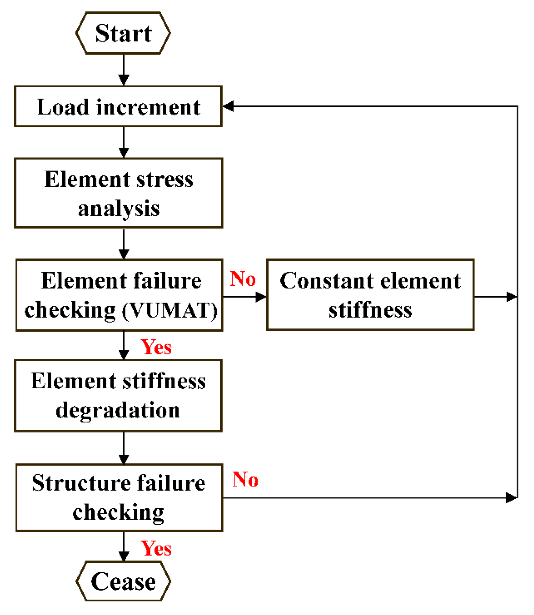
2.2.2. Failure Criteria

In order to facilitate the comparison of the calculation results of the hybrid joint and the adhesive joint, the same bilinear constitutive relation as in [30] is used to simulate the failure process of the adhesive layer. For damage to the bolt, the three-dimensional Hashin failure criterion is used, and it can be expressed as follows:
(1)
Fiber tensile failure ( σ 11 > 0 )
(2)
( σ 11 X T ) 2 + ( τ 11 X T ) 2 + ( τ 13 S 13 ) 2 1
(3)
Fiber compressive failure ( σ 11 < 0 )
(4)
( σ 11 X C ) 2 1
(5)
Matrix tensile failure ( σ 22 > 0 )
(6)
( σ 22 Y C ) 2 + ( τ 12 S 12 ) 2 + ( τ 23 S 23 ) 2 1
(7)
Matrix compressive failure ( σ 22 < 0 )
( σ 22 Y C ) 2 + ( τ 12 S 12 ) 2 + ( τ 23 S 23 ) 2 1
(8)
Matrix/fiber shear failure ( σ 11 < 0 )
( σ 11 X C ) 2 + ( τ 12 S 12 ) 2 + ( τ 13 S 13 ) 2 1
(9)
Tensile delamination failure ( σ 33 > 0 )
( σ 33 Z T ) 2 + ( τ 13 S 13 ) 2 + ( τ 23 S 23 ) 2 1
(10)
Compressive delamination failure ( σ 33 < 0 )
( σ 33 Z C ) 2 + ( τ 13 S 13 ) 2 + ( τ 23 S 23 ) 2 1
where σ 11 , σ 22 , σ 33 , τ 12 , τ 13 , and τ 23 are the respective normal stress and shear stress in the three directions of the element. X T , X C , Y T , Y C , Z T , and Z C are the strength parameters of the element, as shown in Table 1. The element stiffness degradation model of Camanho [34] was adopted for the damage to the bolt element, as shown in Table 3.
The calculation process of progressive damage of composites is demonstrated in Figure 6.

3. Results and Discussion

Due to the interrelation of the load-carrying capacity between the hybrid joint and the bonded joint, the failure mechanism and mechanical properties of the hybrid joint are revealed by comparing the experimental and numerical results of the two kinds of joint.

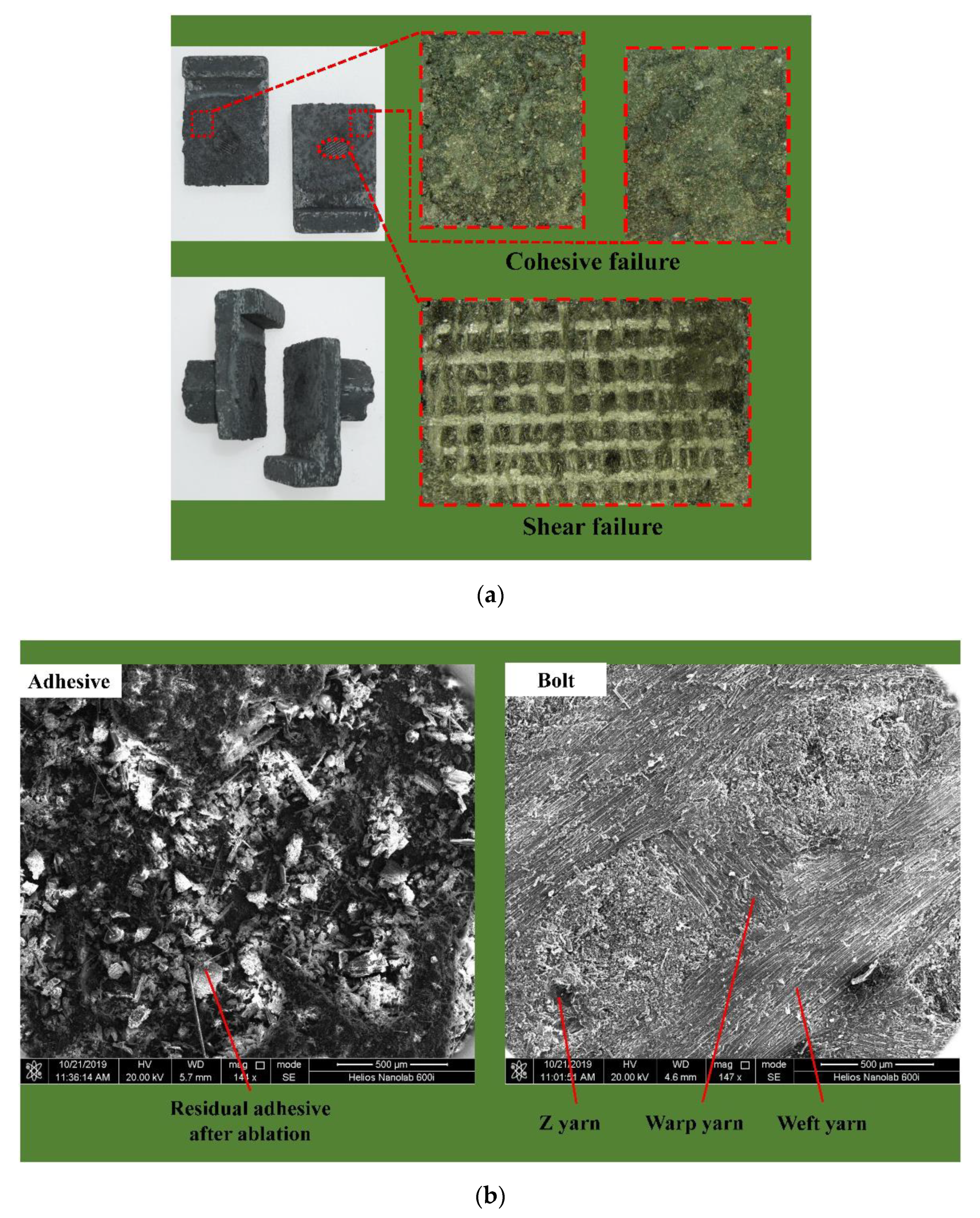
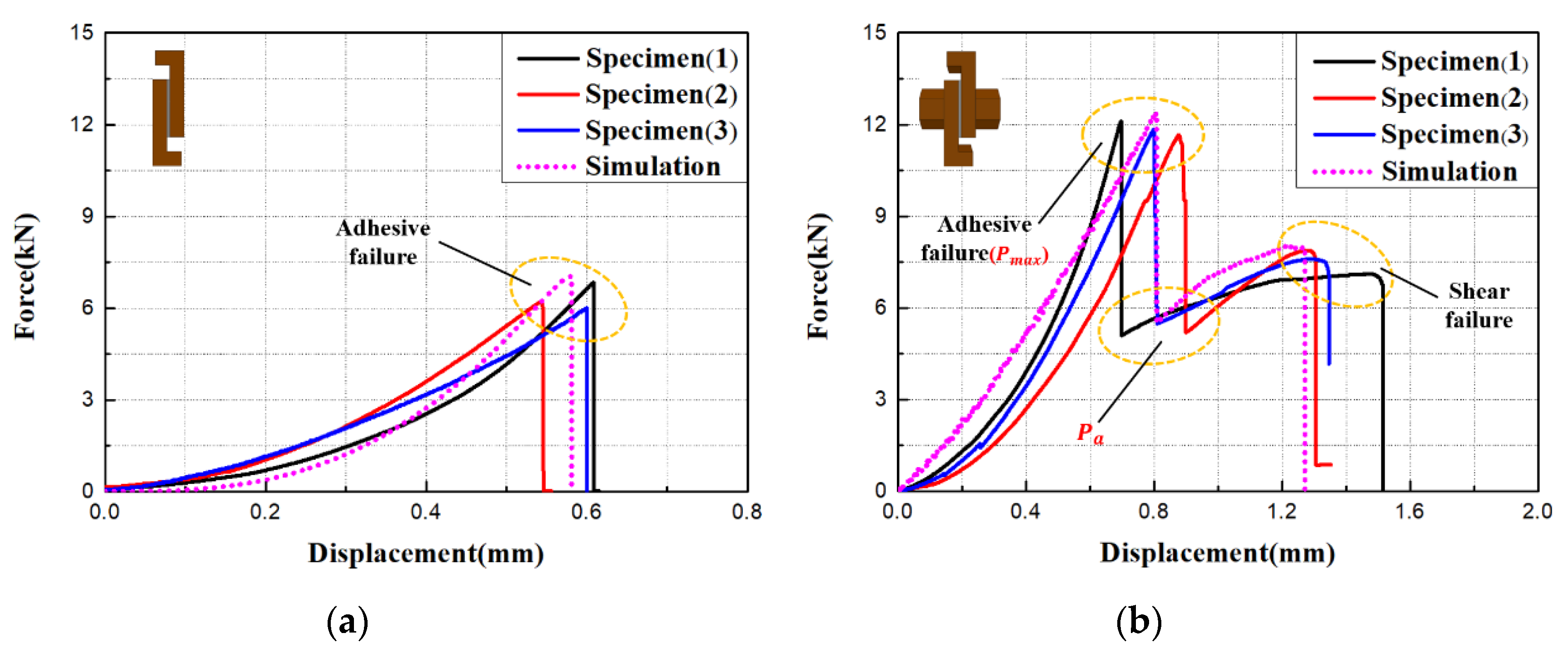
3.1. Failure Mode and Mechanical Response

The compression shear test at 800 °C was conducted on the C/C composite bonded–bolted hybrid single-lap joints. The failure morphology of the test piece after cooling was observed using a digital microscopic system and a scanning electron microscope (Helios Nanolab 600i, FEI, Hillsboro, Oregon, USA), as shown in Figure 7. It can be observed that shear failure occurred in both the adhesive layer and the bolt, and the shear plane of the bolt is flat and coincides with the middle plane of the adhesive layer. The bolt rod had no obvious deformation, and the bolt hole had no obvious extrusion failure, indicating that the bolt rod had a brittle fracture. In contrast to [30], for hybrid joints, the whole adhesive layer exhibited cohesive failure (adhesives were observed on both overlapped plates after the failure), and no interface failure occurs (adhesives were only found on one overlapped plate after the failure). This is due to the secondary bending caused by the eccentricity of the load, which causes the bolt to compress the adhesive layer perpendicular to the lap surface, reducing the peeling behavior of the adhesive layer as shown in Figure 8.
The test and simulation load–displacement curves of C/C composite bonded joints [30] and bonded–bolted hybrid joints at 800 °C are shown in Figure 9, respectively. It can be seen that the load on the hybrid joints had two peaks with the increase of displacement. The load shared by the adhesive layer and the bolt resulted from the hole clearance filled with the cured adhesive. After reaching the first peak, a brittle fracture occurred in the adhesive layer, the load-bearing capacity dropped rapidly, the curve presented as a falling straight line, and the load was then entirely taken by the bolt. Subsequently, the load rose again, the hole wall was compressed, and the bolt was sheared. The eccentricity of the load caused the bolt to bend slightly, resulting in stress concentration on the middle plane of the bolt. Finally, the bolt failed in the shear, and the shear plane was the middle plane of the bolt rod. Similar to bonded joints, the load on the hybrid joints increased nonlinearly until the first peak. In contrast to the bonded joint, the hybrid joint can be seen as replacing the original adhesive layer with a higher modulus adhesive at the center of the adhesive layer. The stiffness of the bonded joints was less than that of the hybrid joints before reaching the first peak, which is because the existence of the bolt increased the overall stiffness of the hybrid joint. The displacement corresponding to the failure point of the adhesive layer in the hybrid joint is greater than the bonded joint, because the existence of the bolt slowed down the crack propagation in the adhesive layer and improved the bearing performance of the joint. For hybrid joints, the failure load of the adhesive layer is defined as Pmax, the load at the point where the curve descended after the failure of the adhesive layer as Pa, and the difference between Pmax and Pa as ∆P. Therefore, ∆P was the load shared by the adhesive layer in the hybrid joints. The experimental limit load and the simulated limit load of the bonded joints and the hybrid joints, as well as ∆P, are given in Figure 10, respectively. The bearing capacity of the adhesive layer in the hybrid joints was slightly higher than the bonded joints. This was also due to the presence of the bolt improving the bearing capacity of the adhesive layer. It can be simultaneously seen that the calculated ultimate load was slightly larger than the data measured in the test due to bubbles, the uneven distribution of the adhesive thickness, and the initial defects of C/C composites, and these factors had not been fully considered in the simulation. Despite these factors, the simulation results maintained good consistency with the test results, reflecting the bearing capacity of the test pieces.

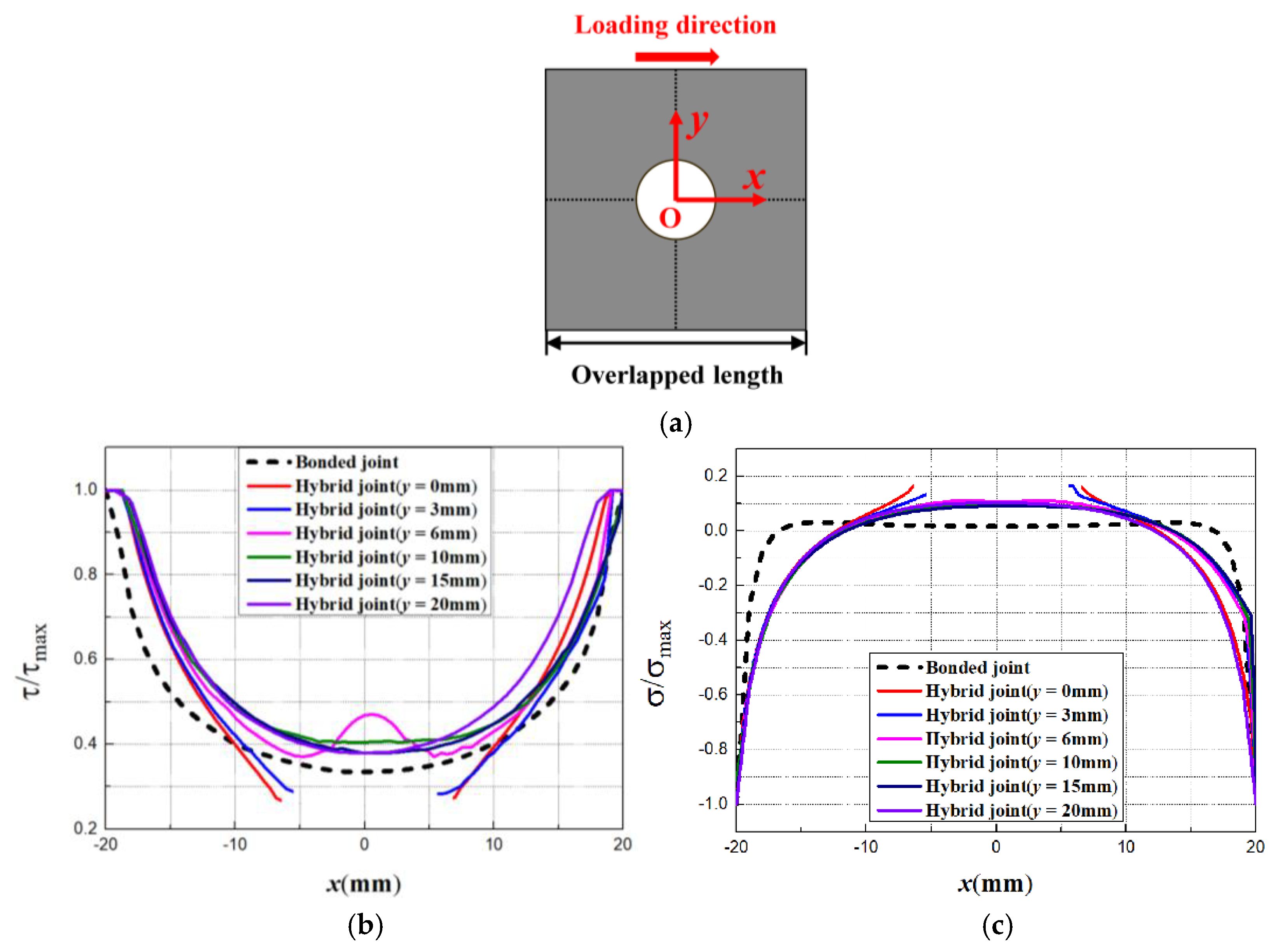
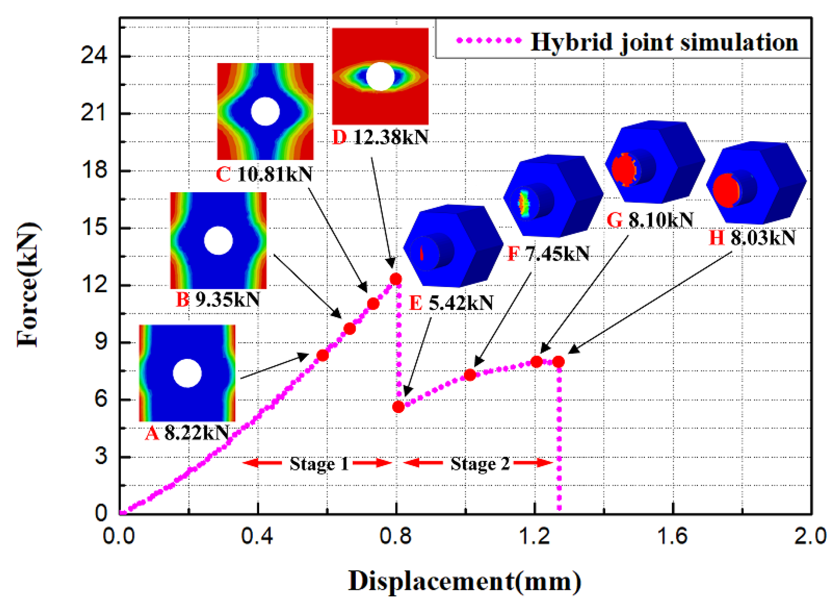
3.2. Stress Distribution and Progressive Damage

Taking the center point of the adhesive layer as the coordinate origin, the loading direction as the x-axis, and the width direction of the lap plate as the y-axis, the coordinate system was established, as shown in Figure 11. The normalized shear stress peeling stress of the adhesive layer in the bonded joint and the variations in normalized shear stress and in peel stress of the adhesive layer in the hybrid with y are also given in Figure 11. When y = 0 mm and y = 3 mm, the existence of the bolt reduced the area of the adhesive layer, which increased the shear stress gradient. The adhesive layer on the edge of the hole (y = 6 mm) indicated an obvious shear stress concentration. The shear stress distribution of the adhesive layer far from the center was similar to that of the bonded joint. The peel stress gradient is lower than that of the bonded joint.
The simulation load–displacement curve of the hybrid joint is shown in Figure 12. Four points A, B, C, and D were taken on the curve at Stage 1 in order to present progressive damage to the adhesive layer. The shear stress of the adhesive layer reached shear strength at Point A, which is the initial point of the damage, and Point D is the adhesive layer failure load point. Similar to [30], the damage evolution process of the adhesive layer was also distributed symmetrically, and the failure region expanded from the edge to the center of the adhesive layer. However, the failure of the adhesive layer near the centerline was slowed down by the bolt. Points E, F, G, and H were taken on the curve at Stage 2. It can be observed that the bolt was slightly damaged when the adhesive layer failed completely, and the bolt damage was aggravated with the further increase of the load. Damage to the element occurred in the middle plane of the bolt and extended from the middle to both sides in the circular section. Due to the eccentric load resulting in the slight deflection of the bolt, the damage is not completely symmetrical. At Point H, shear failure of the bolt rod occurred.

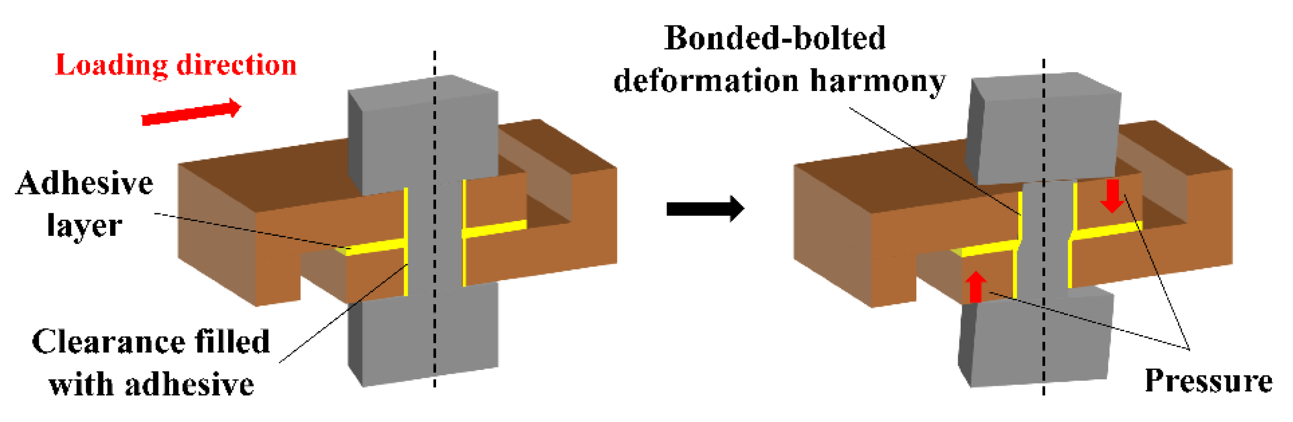
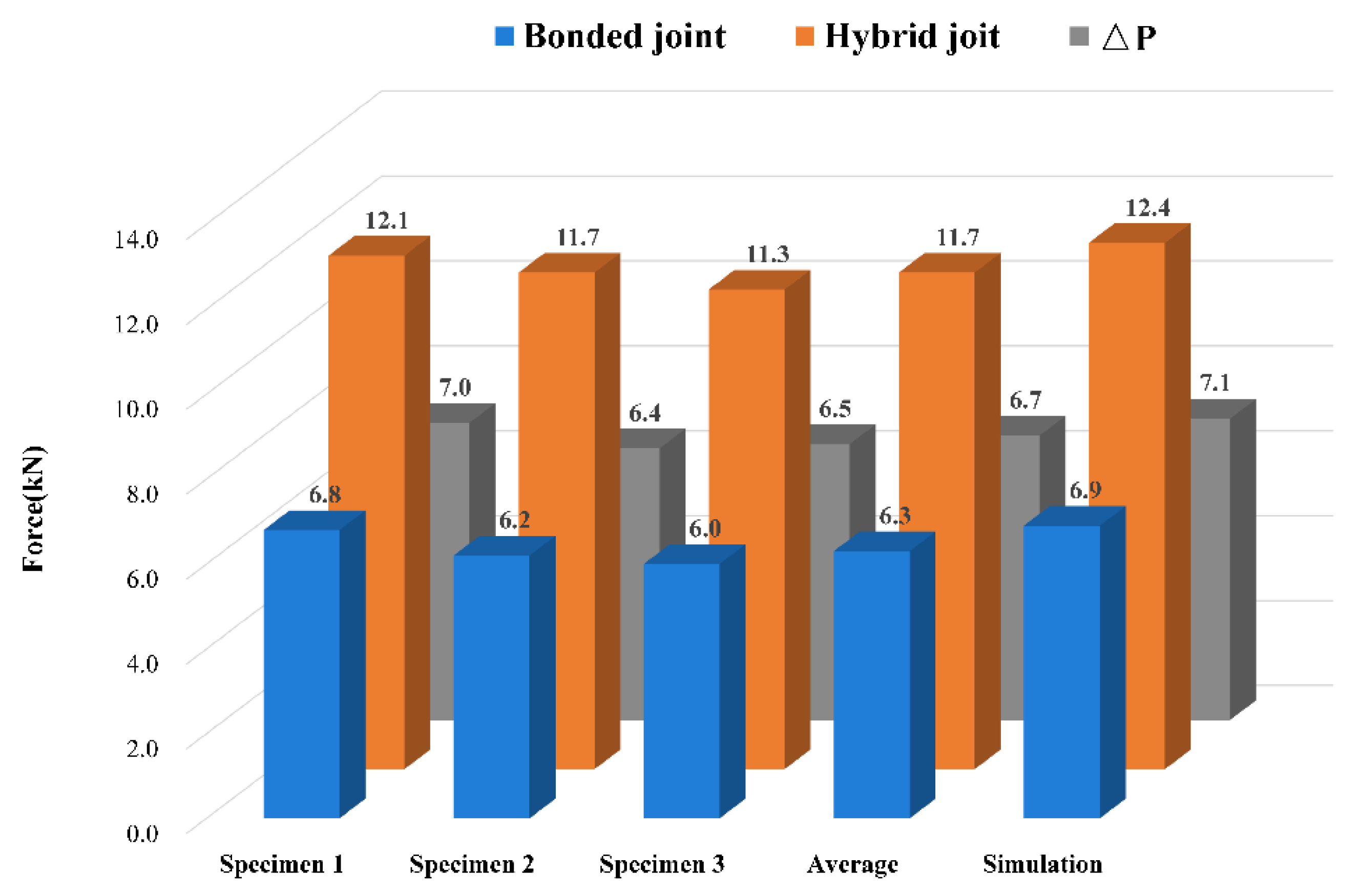
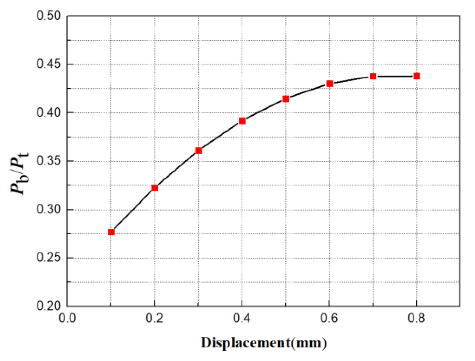
3.3. Bolt Load Transfer

The load-bearing parts of the bonded–bolted hybrid joint include the adhesive layer and the bolt. The load is transferred to the bolt through the adhesive layer when the structure is loaded. Compared with bonded joints, hybrid joints replaced the adhesive layer at the hole in the center of the lap area with a bolt. The adhesive layer in the central region had little effect on the adhesive bearing capacity, such that the load shared by the bolt directly affected the bearing performance of the hybrid joint. The variations in the ratio ( P b / P t ) of the load shared by the bolt to the total load with displacement are shown in Figure 13. The load shared by the bolt is the sum of nodal forces on the middle plane of the bolt [31]. It can be seen that the value of ( P b / P t ) increased nonlinearly with the displacement. This is because the stiffness of the bolt was greater than that of the adhesive, so the bolt shared more load with the same deformation. The rate at which the value increased decreased. The probable cause is the eccentricity of the load resulting in the bolt deflecting slightly, which caused the bolt head to produce the pressure perpendicular to the adhesive layer. The pressure slowed down the crack propagation in the adhesive layer and increased the bearing capacity of the adhesive layer.

4. Conclusions

The compression shear test of C/C composite bonded–bolted hybrid single-lap joints was carried out at 800 °C, the failure process of the joint was obtained through finite element analysis, and the numerical results were compared with the test results to verify the correctness of the model. The failure mode, adhesive layer stress distribution, and progressive damage of the joint were determined. The variations in the ratio of the load shared by the bolt to the total load with displacement were obtained. Some conclusions derived from the experimental and numerical studies can be summarized as follows:
  • The shear plane first appeared on the bonding surface with cohesive failures occurring in the adhesive layer. Shear failure then occurred on the bolt, and the shear plane appeared on the middle plane of the bolt rod.
  • Compared with the bonded joint, the existence of the bolt in the hybrid joint increased the shear stress gradient of the adhesive layer when the y value was smaller, and the distribution of shear stress was close to that of the bonded joint. The peel stress gradient was lower than that of the bonded joint. The failure region expanded from the edge to the center in the adhesive layer, while the failure of the adhesive layer at the centerline was slowed down. The failure region on the middle plane of the bolt rod expanded from the middle to both sides.
  • The ratio of the load shared by the bolt to the total load increased nonlinearly with displacement.

Author Contributions

Conceptualization, Y.Z., Z.Z., and Z.T.; data curation, Y.Z. and Z.Z.; formal analysis, Y.Z.; funding acquisition, Z.Z.; investigation, Y.Z.; methodology, Y.Z. and Z.Z.; project administration, Z.Z. and Z.T.; resources, Z.Z. and Z.T.; software, Y.Z.; validation, Y.Z.; writing—original draft, Y.Z.; writing—review & editing, Y.Z. and Z.Z. All authors have read and agreed to the published version of the manuscript.

Funding

This work was supported by the National Natural Science Foundation of China under Grant No. 11572101.

Acknowledgments

In this study, the supplier of all materials and parameters was the China Academy of Launch Vehicle Technology.

Conflicts of Interest

The authors declare that there is no conflict of interest.

References

  1. Ozel, A.; Yazici, B.; Akpinar, S.; Aydin, M.D. A study on the strength of adhesively bonded joints with different adherends. Compos. Part B Eng. 2014, 62, 167–174. [Google Scholar] [CrossRef]
  2. Kim, K.S.; Yoo, J.S.; Yi, Y.M.; Kim, C.G. Failure mode and strength of uni-directional composite single lap bonded joints with different bonding methods. Compos. Struct. 2006, 72, 477–485. [Google Scholar] [CrossRef]
  3. Turan, K.; Pekbey, Y. Progressive Failure Analysis of Reinforced-Adhesively Single-Lap Joint. J. Adhes. 2015, 91, 962–977. [Google Scholar] [CrossRef]
  4. Da Silva, L.F.M.; Adams, R.D. Adhesive joints at high and low temperatures using similar and dissimilar adherends and dual adhesives. Int. J. Adhes. Adhes. 2007, 27, 216–226. [Google Scholar] [CrossRef]
  5. Guilpin, A.; Franciere, G.; Barton, L.; Blacklock, M.; Birkett, M. A Numerical and Experimental Study of Adhesively-Bonded Polyethylene Pipelines. Polymers 2019, 11, 1531. [Google Scholar] [CrossRef] [Green Version]
  6. Anasiewicz, K.; Kuczmaszewski, J. Adhesive Joint Stiffness in the Aspect of FEM Modelling. Materials 2019, 12, 3911. [Google Scholar] [CrossRef] [Green Version]
  7. Egan, B.; McCarthy, C.T.; McCarthy, C.T.; Gray, P.J.; Frizzell, R.M. Modelling a single-bolt countersunk composite joint using implicit and explicit finite element analysis. Comput. Mater. Sci. 2012, 64, 203–208. [Google Scholar] [CrossRef]
  8. McCarthy, C.T.; McCarthy, M.A.; Lawlor, V.P. Progressive damage analysis of multi-bolt composite joints with variable bolt–hole clearances. Compos. Part B Eng. 2005, 36, 290–305. [Google Scholar] [CrossRef]
  9. Egan, B.; McCarthy, C.T.; McCarthy, M.A.; Frizzell, R.M. Stress analysis of single-bolt, single-lap, countersunk composite joints with variable bolt-hole clearance. Compos. Struct. 2012, 94, 1038–1051. [Google Scholar] [CrossRef] [Green Version]
  10. Nezhad, H.Y.; Egan, B.; Merwick, F.; McCarthy, C.T. Bearing damage characteristics of fibre-reinforced countersunk composite bolted joints subjected to quasi-static shear loading. Compos. Struct. 2017, 166, 184–192. [Google Scholar] [CrossRef] [Green Version]
  11. Hart-Smith, L.J. Bonded-Bolted Composite Joints. J. Aircraft. 1985, 22, 993–1004. [Google Scholar] [CrossRef]
  12. Gomez, S.; Onoro, J.; Pecharroman, J. A simple mechanical model of a structural hybrid adhesive/riveted single lap joint. Int. J. Adhes. Adhes. 2007, 27, 263–267. [Google Scholar] [CrossRef]
  13. Chowdhury, N.; Chiu, W.K.; Wang, J.; Chang, P. Static and fatigue testing thin riveted, bonded and hybrid carbon fiber double lap joints used in aircraft structures. Compos. Struct. 2015, 121, 315–323. [Google Scholar] [CrossRef]
  14. Vallee, T.; Tannert, T.; Meena, R.; Hehl, S. Dimensioning method for bolted, adhesively bonded, and hybrid joints involving Fibre-Reinforced-Polymers. Compos. Part B Eng. 2013, 46, 179–187. [Google Scholar] [CrossRef]
  15. Chowdhury, N.M.; Chiu, W.K.; Wang, J.; Chang, P. Experimental and finite element studies of bolted, bonded and hybrid step lap joints of thick carbon fibre/epoxy panels used in aircraft structures. Compos. Part B Eng. 2016, 100, 68–77. [Google Scholar] [CrossRef]
  16. Ucsnik, S.; Scheerer, M.; Zaremba, S.; Pahr, D.H. Experimental investigation of a novel hybrid metal–composite joining technology. Compos. Part A Appl. Sci. Manuf. 2010, 41, 369–374. [Google Scholar] [CrossRef]
  17. Marannano, G.; Zuccarello, B. Numerical experimental analysis of hybrid double lap aluminum-CFRP joints. Compos. Part B Eng. 2015, 71, 28–39. [Google Scholar] [CrossRef] [Green Version]
  18. Kelly, G. Quasi-static strength and fatigue life of hybrid (bonded/bolted) composite single-lap joints. Compos. Struct. 2006, 72, 119–129. [Google Scholar] [CrossRef]
  19. Mei, H.; Cheng, L.; Ke, Q.; Zhang, L. High-temperature tensile properties and oxidation behavior of carbon fiber reinforced silicon carbide bolts in a simulated re-entry environment. Carbon 2010, 48, 3007–3013. [Google Scholar] [CrossRef]
  20. Li, S.; Chen, X.; Chen, Z. The effect of high temperature heat-treatment on the strength of C/C to C/C–SiC joints. Carbon 2010, 48, 3042–3049. [Google Scholar] [CrossRef]
  21. Bruneton, E.; Narcy, B.; Oberlin, A. Carbon-carbon composites prepared by a rapid densification process I: Synthesis and physico-chemical data. Carbon 1997, 35, 1593–1598. [Google Scholar] [CrossRef]
  22. Virgil’ev, Y.S.; Kalyagina, I.P. Carbon–Carbon Composite Materials. Inorg. Mater. 2004, 40, S33–S49. [Google Scholar] [CrossRef]
  23. Buckley, J.D.; Edie, D.D. Carbon–Carbon Materials and Composites; Noyes Publications: New Jersey, NJ, USA, 1993. [Google Scholar]
  24. Lim, D.W.; Kim, T.H.; Choi, J.H.; Kweon, J.H.; Park, H.S. A study of the strength of carbon–carbon brake disks for automotive applications. Compos. Struct. 2008, 86, 101–106. [Google Scholar] [CrossRef]
  25. Li, K.Z.; Shen, X.T.; Li, H.J.; Zhang, S.Y.; Feng, T.; Zhang, L.L. Ablation of the carbon/carbon composite nozzle-throats in a small solid rocket motor. Carbon 2011, 49, 1208–1215. [Google Scholar] [CrossRef]
  26. Christin, F. Design, fabrication, and application of thermostructural composites (TSC) like C/C, C/SiC, and SiC/SiC composites. Adv. Eng. Mater. 2002, 4, 903–912. [Google Scholar] [CrossRef]
  27. Windhorst, T.; Blount, G. Carbon-carbon composites: A summary of recent developments and applications. Mater. Des. 1997, 18, 11–15. [Google Scholar] [CrossRef]
  28. Kumar, S.; Kushwaha, J.; Mondal, S.; Kumar, A.; Jain, R.K.; Devi, J.G. Fabrication and ablation testing of 4D C/C composite at 10MW/m2 heat flux under aplasma arc heater. Mater. Sci. Eng. A 2013, 566, 102–111. [Google Scholar] [CrossRef]
  29. Sun, C.T.; Kumar, B. Development of Improved Hybrid Joints for Composite Structures. Compos. Struct. 2005, 35, 1–20. [Google Scholar]
  30. Zhang, Y.; Zhou, Z.; Tan, Z. Compression Shear Properties of Adhesively Bonded Single-Lap Joints of C/C Composite Materials at High Temperatures. Symmetry 2019, 11, 1437. [Google Scholar] [CrossRef] [Green Version]
  31. Dassault Systemes Simulia Corp. Abaqus Analysis User’s Manual 6.14; Dassault Systemes Simulia Corp: Providence, RI, USA, 2014. [Google Scholar]
  32. Kelly, G. Load transfer in hybrid (bonded/bolted) composite single-lap joints. Compos. Struct. 2005, 69, 35–43. [Google Scholar] [CrossRef]
  33. Hashin, Z. Failure Criteria for Unidirectional Fiber Composites. J. Appl. Mech. 1980, 47, 329–334. [Google Scholar] [CrossRef]
  34. Camanho, P.P.; Matthews, F.L. A progressive damage model for mechanically fastened joints in composite laminates. J. Compos. Mater. 1999, 33, 2248–2280. [Google Scholar] [CrossRef]
Figure 1. (a) The preform weaving mode and fiber direction; (b) microstructure of C/C fasteners.
Applsci 10 01054 g001aApplsci 10 01054 g001b
Figure 2. (a) C/C plate and fastener before and after anti-oxidation treatment; (b) geometric dimensions of the specimen.
Applsci 10 01054 g002
Figure 3. Fixture and loading method.
Applsci 10 01054 g003
Figure 4. Adhesive thickness control method.
Applsci 10 01054 g004
Figure 5. (a) Parts and constraints; (b) mesh generation and boundary conditions; (c) master and slave surfaces in each contact pair.
Applsci 10 01054 g005aApplsci 10 01054 g005b
Figure 6. Calculation process of the bolt progressive damage.
Applsci 10 01054 g006
Figure 7. (a) Failure morphology observed by the digital microscopic system; (b) failure morphology observed by scanning electron microscopy.
Applsci 10 01054 g007
Figure 8. Bolt loading mechanism.
Applsci 10 01054 g008
Figure 9. Test and simulation load–displacement curve: (a) bonded joints; (b) hybrid joints.
Applsci 10 01054 g009
Figure 10. The comparison of the bearing capacity of the two kinds of joints.
Applsci 10 01054 g010
Figure 11. The schematic of overlapped length (a); the normalized shear stress (b) and peeling stress (c) of the adhesive layer in the two kinds of joints.
Applsci 10 01054 g011
Figure 12. Progressive damage of the hybrid joint.
Applsci 10 01054 g012
Figure 13. The variations in the ratio of the load shared by the bolt to the total load with displacement.
Applsci 10 01054 g013
Table 1. Material performance of the adherend and fastener at 800 °C.
VariableAdherendFastenerVariableAdherendFastener
Density (g/cm3)1.651.78Tensile strength
X T (MPa)
271.3254.6
Coefficient of thermal expansion (10−6 °C)0.190.17Compression strength
X C (MPa)
224256
Elastic modulus
E 11 (GPa)
9598.2Tensile strength
Y T (MPa)
271.3254.6
Elastic modulus
E 22 (GPa)
9598.2Compression strength
Y C (MPa)
224256
Elastic modulus
E 33 (GPa)
10.361.8Tensile strength
Z T (MPa)
84.980.7
Shear modulus
G 12 (GPa)
27.613.2Compression strength
Z C (MPa)
358308
Shear modulus
G 13 = G 23 (GPa)
6.87.1Shear strength
S 12 (MPa)
54.548.7
Poisson ratio
ν 12
0.0350.036Shear strength
S 13 = S 23 (MPa)
18.265.9
Poisson ratio
ν 12 = ν 23
0.0320.035
Table 2. Process parameters of chemical vapor infiltration (CVI) and chemical vapor deposition (CVD).
EquipmentTemperature(°C)Source GasDiluting Gas
AdherendCVIZRHC-1500 CVD system (SANTE VACUUM TECHNOLOGY)1000~1300C2H2Ar
CVD673~1173CH3SiCl3Ar
FastenerCVI900~1100CH4Ar
CVD673~1173CH3SiCl3Ar
Table 3. Element stiffness degradation mode.
Failure ModeStiffness Degradation
Fiber tension E 11 = 0.07 E 11
Fiber compression E 11 = 0.07 E 11
Fiber tension E 22 = 0.2 E 22 , G 22 = 0.2 G 22 , G 23 = 0.2 G 23 ,
Fiber compression E 22 = 0.4 E 22 , G 12 = 0.4 G 12 , G 23 = 0.4 G 23 ,
Matrix/fiber shear G 12 = 0 , ν 12 = 0
Delamination E 22 = 0 , G 13 = 0 , G 23 = 0 , ν 13 = 0

