Article

Applicability of Formwork Automation Design Software for Aluminum Formwork

1
Intelligent Construction Automation Center, Kyungpook National University, Daegu 41566, Korea
2
School of Architecture, Civil, Environment, and Energy, Kyungpook National University, Daegu 41566, Korea
3
Mn-nH Inc., Seoul 04793, Korea
*
Authors to whom correspondence should be addressed.
These authors contributed equally to this work as corresponding authors.
Appl. Sci. 2020, 10(24), 9029; https://doi.org/10.3390/app10249029
Submission received: 10 November 2020 / Revised: 14 December 2020 / Accepted: 14 December 2020 / Published: 17 December 2020

Abstract

:
In this study, by applying the developed formwork automation design software to three target structures, we reviewed the applicability of the formwork automation design software for the aluminum formwork. To apply the formwork automation design software, we built an aluminum formwork library based on the conversion of two-dimensional (2D) computer-aided design (CAD) data to three-dimensional building information modeling data for all the components of the aluminum formwork. The results of the automated formwork layout on the target structures using the formwork automation design software confirmed that the wall and deck members were laid out by the set algorithm according to the formwork size and direction. However, because of the limited functionality of the software, the level of completion of the formwork layout was found to be lower than that of the manual formwork layout based on 2D CAD data. The currently developed software is based on a simple algorithm, but has a drawback in that the automated layout is limited to only some of its members. Therefore, additional research should be conducted on the development of advanced software through the diversification of the algorithm, automation of preprocessing of the mesh, and analysis of the relationships of all the members comprising the formwork.

1. Introduction

Temporary work that includes temporary structures used to support building construction, such as formwork, is one of the crucial cost factors in construction work [1]. In temporary work, the way in which temporary structures are planned has a significant influence on the entire project [2,3,4], given that the planning of temporary structures is affected by dynamically changing conditions and characteristics of construction sites. However, temporary structures such as formwork are installed on construction sites without sufficient planning and analysis that may lead to safety-related accidents [5,6,7,8].
The quantity of formwork has mainly been calculated by manually laying out formwork based on two-dimensional (2D) computer-aided design (CAD) data. However, given that this method relies heavily on the knowledge and experience of formwork designers, the outcomes can vary depending on their skill levels. This makes it difficult to verify the objectivity and efficiency of the formwork design. In addition, if inaccurate 2D CAD data are prepared owing to designer mistakes, defects in the manufacturing of formwork may occur.
To address these issues, studies have applied various algorithms and advanced systems to formwork design [9,10,11,12,13,14,15,16,17]. A study was conducted on the automation of the formwork system based on the development of building information modeling (BIM) software using Revit and AutoCAD [11]. However, this formwork system is a proprietary system of Revit software, and the available research results are thus limited. A study was also conducted that set up a plan for the use of the formwork. and calculated the amount of formwork required for a project based on the use of the data extracted from the BIM model [12]. A study was conducted to propose a search algorithm to optimize formwork panels [14]. Research has also been conducted on an automated form layout system that arranged standard and nonstandard slab forms to increase work efficiency and reduce manufacturing costs [15]. As observed in these studies, there are recent approaches to formwork design that use advanced methods, moving away from the traditional method of formwork design based on 2D CAD data.
Meanwhile, formwork manufacturing companies have been developing various programs to support formwork design. For instance, typical programs include Tekla Structures, PERI CAD, ELPOS, Tipos, and DokaCad [14]. However, using these programs is inconvenient given that formwork designers need to directly set contact points. Furthermore, the formwork layout plan may be used in different ways depending on the designers, thus resulting in many errors around obstacles. Accordingly, formwork manufacturing companies have been conducting studies on the development of three-dimensional (3D)-based formwork automation design software, but this is still at the research stage. An accurate design is essential for formwork. Given that it takes a significant amount of time to calculate the quantity of materials and to prepare drawings, the development of formwork automation design software is essential.
We developed formwork automation design software based on the conversion of the randomly arranged vertices among the BIM data of the target structures to a specific form based on certain rules, followed by the setting of specific rules for the face. In this study, by applying the developed formwork automation design software to three target structures, we reviewed the applicability of the formwork automation design software for the aluminum formwork.

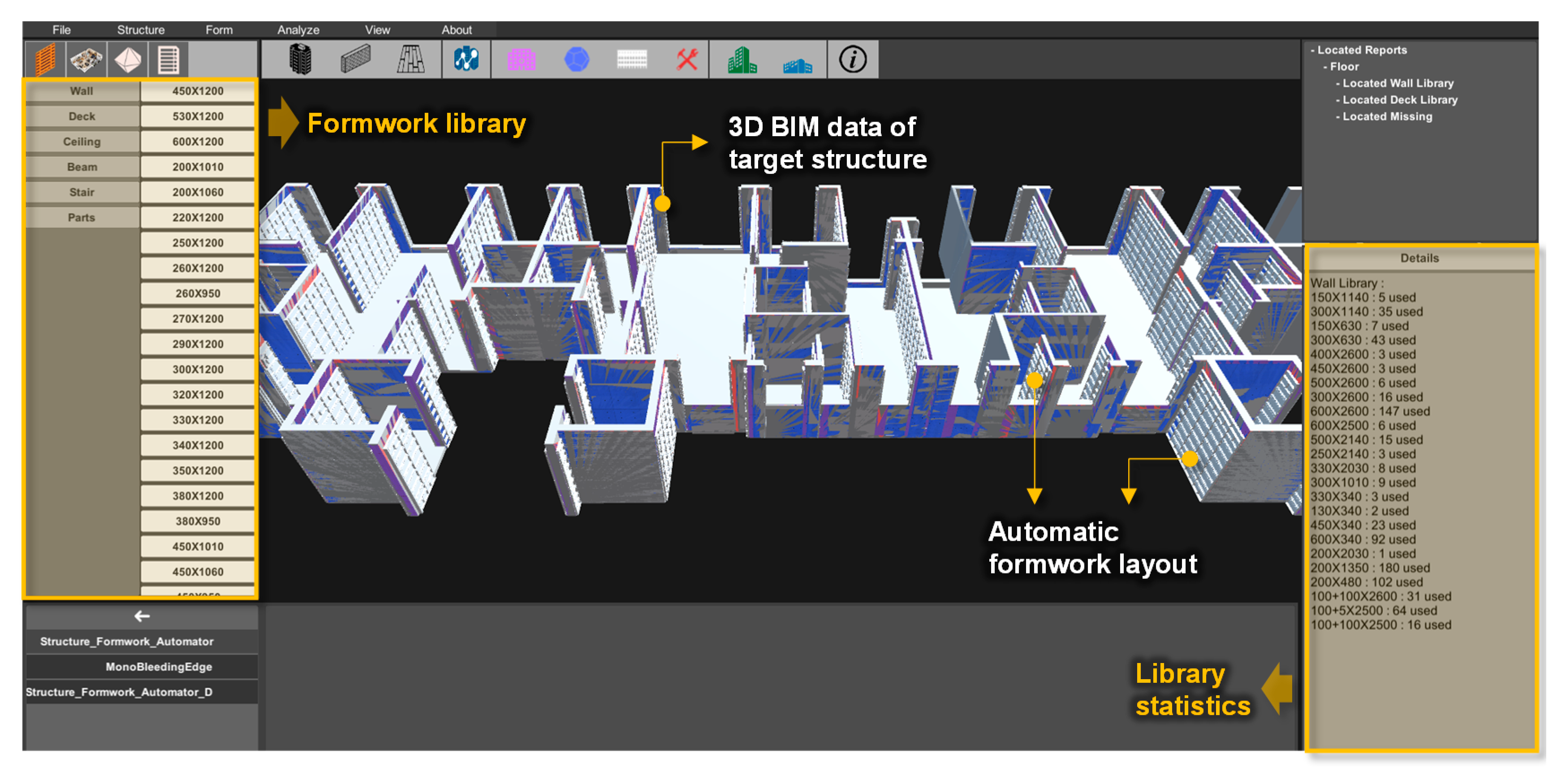
2. Formwork Automation Design Software

The formwork automation design software was developed in the Unity3D environment that is extensively used for industrial applications. In addition, we developed software in the Blender3D development environment for the preprocessing of the mesh of BIM 3D rendering data, and we used a Python script to automate the formwork layout.
To develop the software, we used an aluminum formwork as the formwork type. After the selection of the target structures, we converted the 2D CAD data into 3D BIM data. For the automated formwork layout, we converted the randomly arranged vertices among the BIM data of the target structures to a form based on specific rules, and converted the mesh all at once using an algorithm that fills the 3D model with a regular square mesh. Based on this, we constructed a vertex set 3D model with certain rules. In addition, we set specific rules for the face and built an algorithm by prioritizing them. Figure 1 shows an operational image of the developed software. The results of running the software confirmed that it was possible to automatically lay out the wall and deck members that were components of the aluminum formwork. Statistics were calculated after an automated formwork layout was completed. We were able to identify the type and quantity of formwork. Moreover, we were able to verify the position of the parts where the formwork was not laid out.

3. Applicability of Formwork Automation Design Software

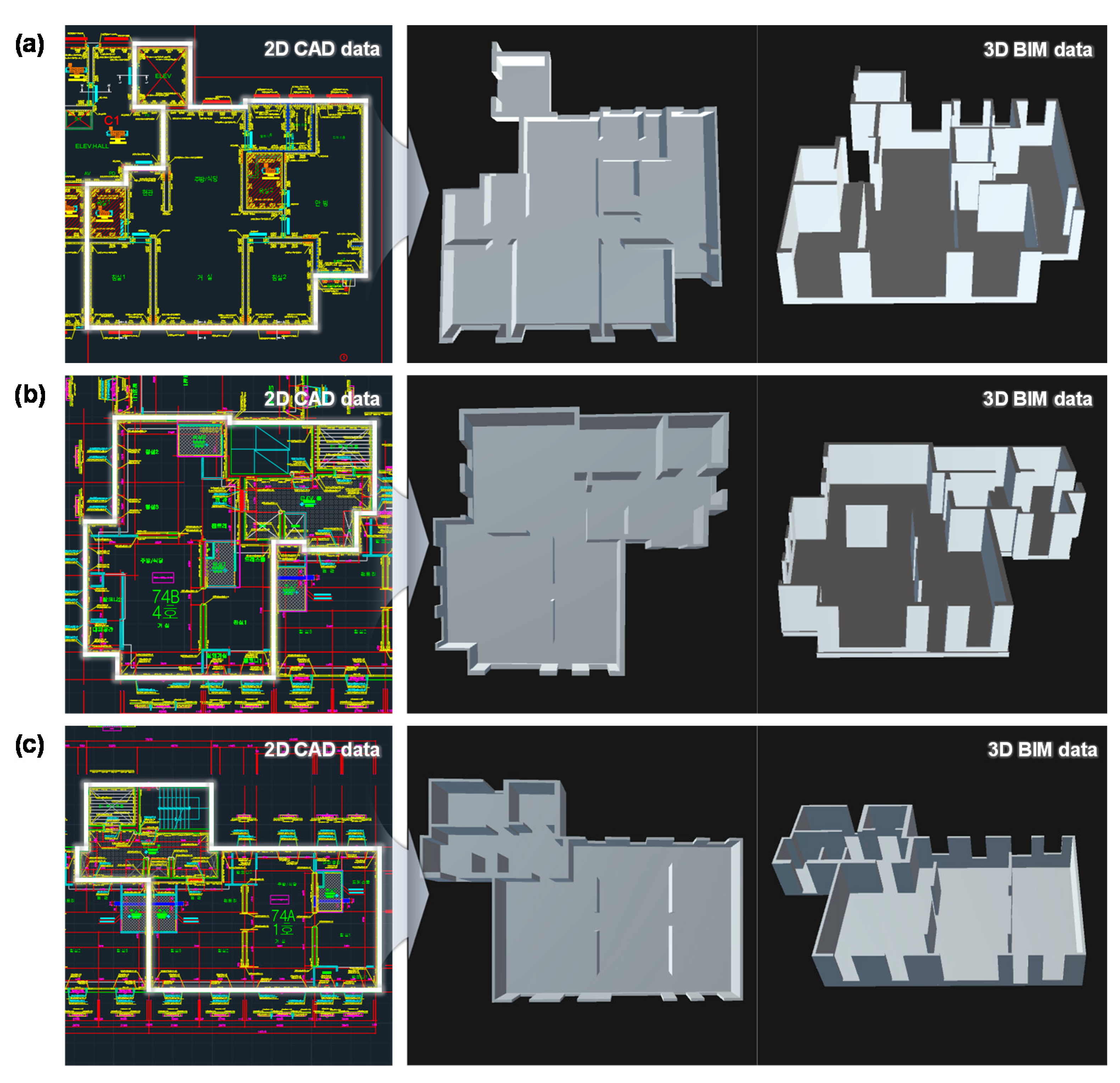
3.1. Overview of Target Structure

To investigate the applicability of the formwork automation design software, we compared the results of the manual formwork layout with the results of the automated formwork layout with the software by selecting target structures. We classified the target structures as A, B, or C types, based on the selection of one household from different types of apartments.
As shown in Figure 2, the 2D CAD data of the target structures of the A, B, and C types were converted into 3D BIM data so that they could be run in the developed formwork automation design software.

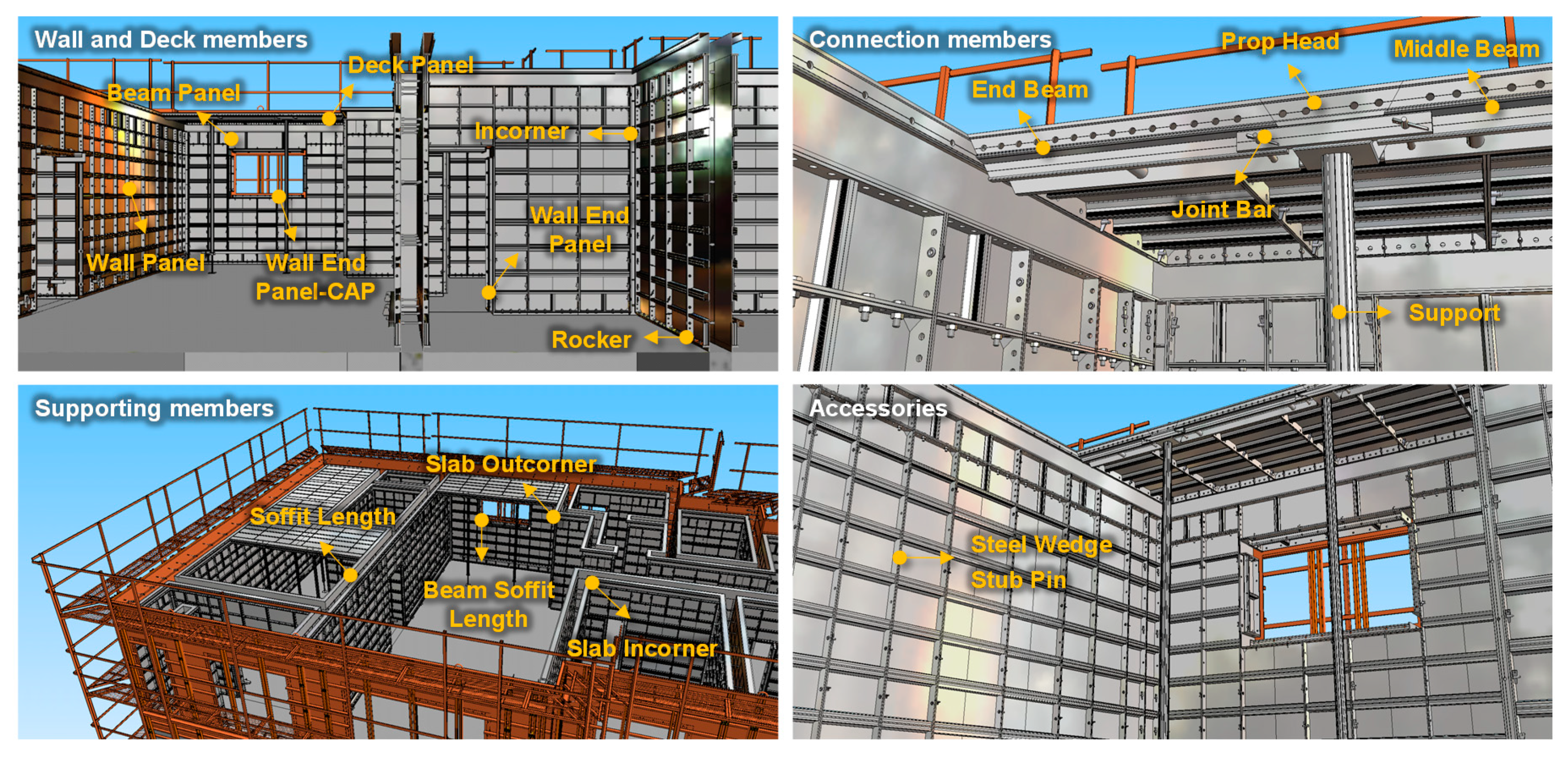
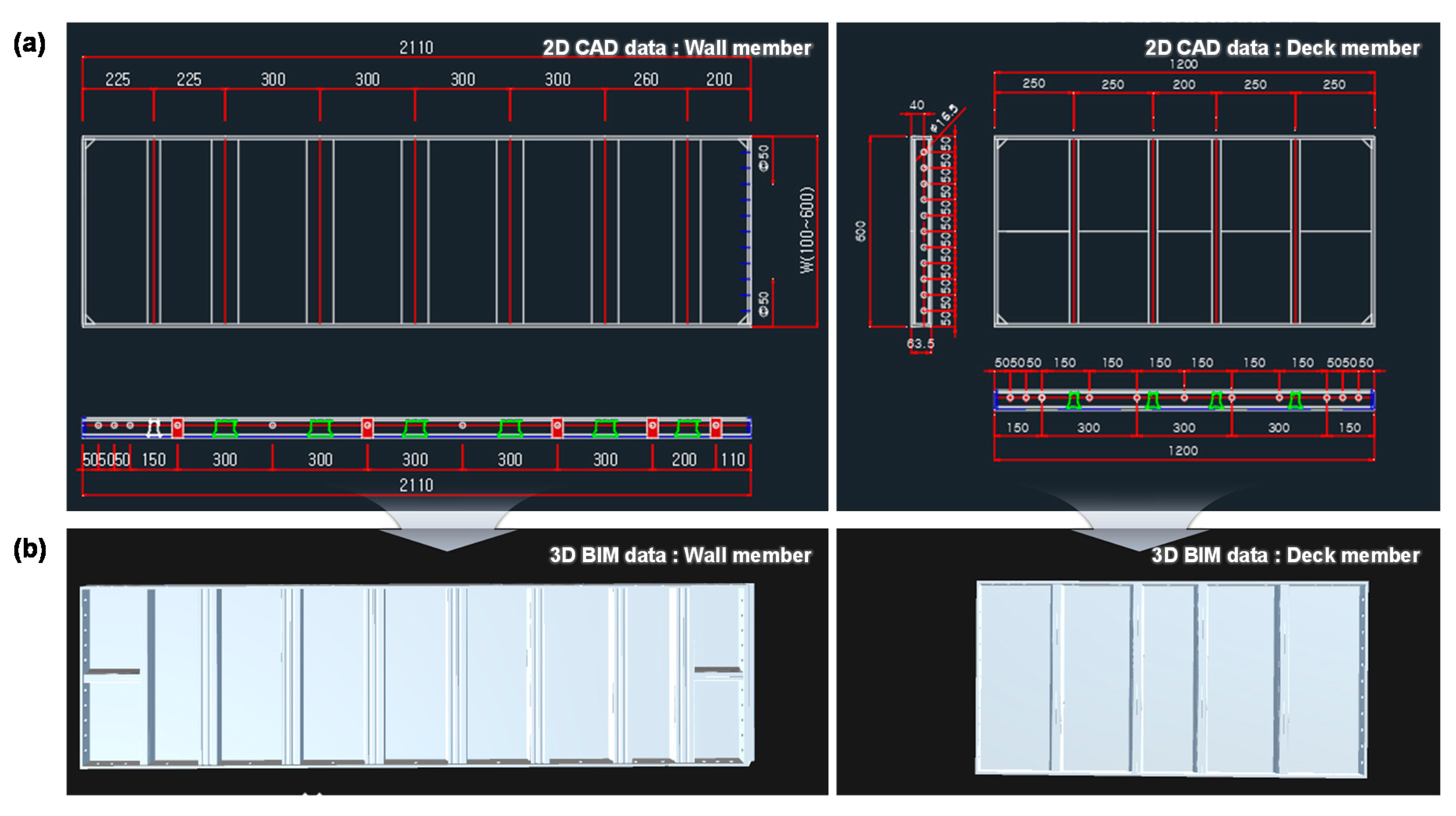
3.2. Aluminum Formwork Library

The aluminum formwork is composed of the wall and deck members, connection members, supporting members, and accessories, as shown in Figure 3 [18]. Aluminum formwork is mainly used in apartment houses with the same plane and has the advantage of being reused multiple times. For the reuse of formwork, installation and disassembly should be straightforward, and it should be structurally safe. Aluminum formwork with these features is composed of various members, and it is crucial to design it without missing any member.
As shown in Figure 4a, the aluminum formwork is designed and manufactured using 2D CAD data. However, to automatically lay out the aluminum formwork, it is necessary to convert it into a form applicable to the software. Therefore, we built a library by converting the 2D CAD data of the aluminum formwork to 3D BIM data, as shown in Figure 4b, and applied this to the formwork automation design software.

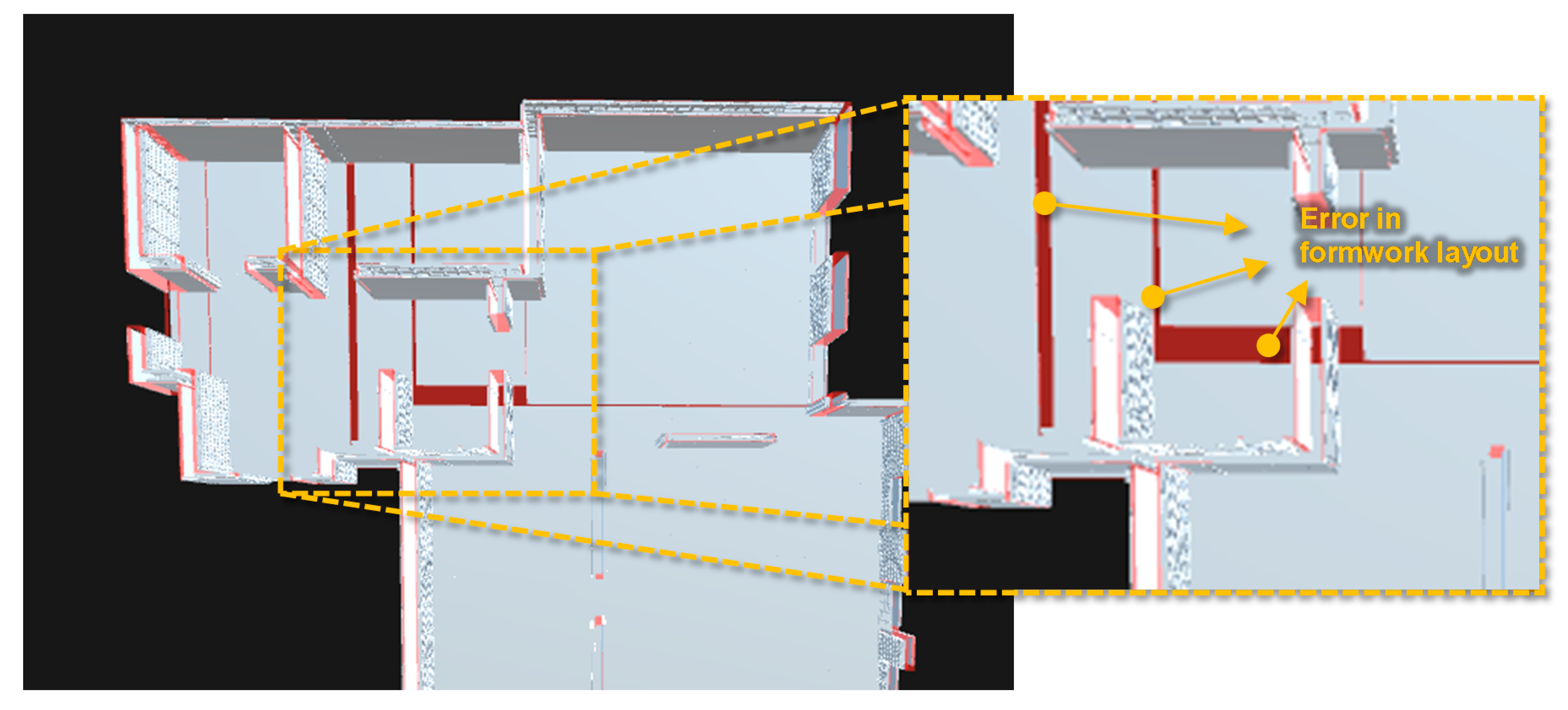
3.3. Formwork Layout Results

Table 1 lists the formwork layout results for the target structures with types A, B, and C, and Table 2 shows formwork layout images. If the formwork is manually laid out based on 2D CAD data, all components required for the formwork layout are included in the design. However, given that this software was developed to assist designers to automatically lay out formwork only for the wall and deck members, we performed an analysis by focusing only on these elements.
The results of the automated formwork layout on the target structure types A, B, and C confirmed that the formwork was laid out according to the formwork size and direction by the set algorithm. For the target structure with type A, we confirmed that the largest formwork in the library was extensively used. The target structures with types B and C exhibited similar tendencies. This result was derived in the automated formwork layout because the algorithm was configured to first lay out the largest formwork.
The manual formwork layout method uses various sizes and types of formwork, and approximately 100 different wall and deck members were found to be actually used for one target structure. However, the automated formwork layout method uses a software method that allows the user to construct the layout based on a prioritized algorithm. It can be observed that the types of formwork used in the formwork layout of the target structures can be reduced by the algorithm that first lays out the large formwork.
Conversely, the results of the automated formwork layout obtained with the use of the software showed that formwork was not laid out in the cases of the parts of 322, 292, and 321 for the target structures with types A, B, and C, respectively. As previously described, the aluminum formwork was composed of various members, and various components were designed in units.
However, because the current software was developed in advance to review its applicability for the automated formwork layout of the wall and deck members only, the components of the connection members, supporting members, and accessories were not taken into account for the automated formwork layout. Accordingly, errors have arisen, and there is a need to ameliorate or eliminate these.
If the software is developed at the practical operating level, the labor time required for formwork design and the cost required for temporary work can be reduced. Furthermore, the objectivity of formwork that was designed based on the subjective judgment of formwork designers can be increased by using the software, and errors caused by formwork designer mistakes can also be avoided. It is difficult to address situations where the available formwork is limited, or a specific formwork cannot be used, using the manual formwork layout method. However, the automated formwork layout method with this software has the advantage of addressing unexpected situations based on algorithm changes to apply a limited quantity of formwork or to exclude unusable formwork from library. In addition, if the formwork layout is completed by changing the software algorithm, the optimal formwork design results can be derived easily and quickly by the manual formwork layout method.
By running the software, we can confirm in real time that formwork is laid out on the target structures. This can reduce the time required to interpret the results of the manual formwork layout based on 2D CAD data. Moreover, as shown in Figure 5, we can easily check and analyze information on these parts because we can monitor in real-time the parts where the formwork is not laid out.

3.4. Limitations and Improvement Direction of the Developed Software

The algorithm applied to the software recognizes the face of the target structures, including walls and decks, and then automatically lays out the formwork according to each attribute. The currently developed software can deploy an aluminum formwork library. However, depending on the form of the face, it is required to add an algorithm so that the software runs stably, and performs tasks such as the separation of the inner and outer edges of target structures, or completing the layout of the components of unitized formwork. It is considered that this can achieve structurally stable, automated formwork layouts based on the analysis of target structures with more complex forms.
The currently developed software is composed of an algorithm that lays out formwork by taking into account the vertical direction first. After this, it lays out a formwork by taking into account the transverse direction for the parts where formwork was not laid out. Because this method is simple, it is considered to be useful in construction sites if a library containing information—such as the unit price of formwork and the inventory status—is built, followed by the development of an algorithm to achieve this.
For the structural analysis of target structures, there is a need to comprehensively analyze points, lines, and faces. However, it is impossible to analyze general 3D BIM data because of the randomly arranged vertices. The software developed in this study converted the vertices into regular and essential forms based on the preprocessing of the mesh. In this way, it is expected that the 3D BIM data of various target structures can be applied directly to the software if the processing of the mesh, which is the prework required for automated formwork layout, is automated.
As described above, the developed software automatically lays out only the wall and deck members. However, to use the software in actual construction sites, it is necessary to automatically lay out the wall and deck members, the connection members, supporting members, and accessories. To automatically lay out these members, the structural analysis of the implemented target structures should be executed by the software, but also information on the layout form and connection parts between members should be identified.
For example, supporting members should be laid out by connecting the end beam, prop head, and middle beam. In addition, given that the end/middle beam and prop head must be connected by a joint bar, this information must be recognized by the software. Therefore, it is necessary to analyze the relationships among all members along with the informatization of the formwork library.
In these cases, there is a need for the development of advanced software through the diversification of the algorithm, automation of preprocessing of the mesh, analysis of the connection relationship of all members making up the formwork, and implementation of an automated formwork layout.

4. Conclusions

In this study, we confirmed the results of the automated formwork layout and reviewed the direction of improvement based on the application of the formwork automation design software developed for labor-reduction of temporary work to three target structures. As a result, we derived the following conclusions:
(1) To apply the formwork automation design software, we confirmed that it was possible to construct an aluminum formwork library by converting 2D CAD to 3D BIM data for all the components of the aluminum formwork.
(2) The results of the automated formwork layout with the use of the formwork automation design software confirmed that the wall and deck members were laid out according to the formwork size and direction defined by the set algorithm. By using the software, it can be observed that the types of formwork used in the formwork layout of the target structures can be reduced by the algorithm that first laid out large formworks.
(3) The automated formwork layout method can manage unexpected situations based on changes in the algorithm. Correspondingly, it is expected that the optimal formwork design outcome can be derived easily and quickly compared with the manual formwork layout method. Furthermore, given that we can monitor in real time the parts where the formwork is not laid out, we can easily check and analyze information related to these parts.
(4) The currently developed software is automatically deployed to only some of these members. Therefore, it is considered that additional research on the development of advanced software should be conducted based on the diversification of the algorithm, automation of preprocessing of the mesh, and analysis of the relationships of all the members comprising the formwork.

Author Contributions

Conceptualization, B.L. and H.C.; methodology, B.L. and B.M.; validation, H.C. and B.L.; formal analysis, B.L. and H.C.; investigation, B.L. and B.M.; data curation, B.L.; writing—original draft preparation, B.L.; writing—review and editing, B.L. and B.M.; visualization, H.C.; supervision, H.C. and D.-E.L.; project administration, H.C. and D.-E.L.; funding acquisition, H.C. and D.-E.L. All authors have read and agreed to the published version of the manuscript.

Funding

This research was funded by the Korean government (MIST), grant number 2018R1A5A1025137.

Acknowledgments

This work was supported by the National Research Foundation of Korea (NRF), grant funded by the Korean government (MSIT) (No. 2018R1A5A1025137).

Conflicts of Interest

The authors declare no conflict of interest.

References

  1. Ko, C.H.; Wang, W.C.; Kuo, J.D. Improving formwork engineering using the Toyota Way. J. Eng. Proj. Prod. Manag. 2011, 1, 13–27. [Google Scholar] [CrossRef]
  2. Kim, K.; Teizer, J. Automatic design and planning of scaffolding systems using building information modeling. Adv. Eng. Inform. 2014, 28, 66–80. [Google Scholar] [CrossRef]
  3. Kim, K.; Cho, Y.; Zhang, S. Integrating work sequences and temporary structures into safety planning: Automated scaffolding-related safety hazard identification and prevention in BIM. Autom. Constr. 2016, 70, 128–142. [Google Scholar] [CrossRef]
  4. Tam, C.M.; Tong, T.K.; Lau, T.C.; Chan, K.K. Selection of vertical formwork system by probabilistic neural networks models. Constr. Manag. Econ. 2005, 23, 245–254. [Google Scholar] [CrossRef]
  5. Suraji, A.; Duff, A.R.; Peckitt, S.J. Development of causal model of construction accident causation. J. Constr. Eng. Manag. 2001, 127, 337–344. [Google Scholar] [CrossRef]
  6. Hallowell, M.R.; Gambatese, J.A. Activity-based safety risk quantification for concrete formwork construction. J. Constr. Eng. Manag. 2009, 135, 990–998. [Google Scholar] [CrossRef]
  7. Whitaker, S.M.; Graves, R.J.; James, M.; McCann, P. Safety with access scaffolds: Development of a prototype decision aid based on accident analysis. J. Saf. Res. 2003, 34, 249–261. [Google Scholar] [CrossRef]
  8. Huang, R.Y.; Chen, J.J.; Sun, K.S. Planning gang formwork operations for building construction using simulations. Autom. Constr. 2004, 13, 765–779. [Google Scholar] [CrossRef]
  9. Kim, T.; Lim, H.; Lee, U.K.; Cha, M.; Cho, H.; Kang, K.I. Advanced formwork method integrated with a layout planning model for tall building construction. Can. J. Civ. Eng. 2012, 39, 1173–1183. [Google Scholar] [CrossRef]
  10. Kim, H.; Anderson, K.; Lee, S.; Hildreth, J. Generating construction schedules through automatic data extraction using open BIM (building information modeling) technology. Autom. Constr. 2013, 35, 285–295. [Google Scholar] [CrossRef]
  11. Kannan, M.R.; Santhi, M.H. Constructability assessment of climbing formwork systems using building information modeling. Proced. Eng. 2013, 64, 1129–1138. [Google Scholar] [CrossRef] [Green Version]
  12. Mansuri, D.; Chakraborty, D.; Elzarka, H.; Deshpande, A.; Gronseth, T. Building information modeling enabled cascading formwork management tool. Autom. Constr. 2017, 83, 259–272. [Google Scholar] [CrossRef]
  13. Lee, J.; Park, Y.J.; Choi, C.H.; Han, C.H. BIM-assisted labor productivity measurement method for structural formwork. Autom. Constr. 2017, 84, 121–132. [Google Scholar] [CrossRef]
  14. Lee, D.; Lim, H.; Kim, T.; Cho, H.; Kang, K.I. Advanced planning model of formwork layout for productivity improvement in high-rise building construction. Autom. Constr. 2018, 85, 232–240. [Google Scholar] [CrossRef]
  15. Lee, C.; Ham, S. Automated system for form layout to increase the proportion of standard forms and improve work efficiency. Autom. Constr. 2018, 87, 273–286. [Google Scholar] [CrossRef]
  16. Jiang, L.; Leicht, R.M. Automated rule-based constructability checking: Case study of formwork. J. Manag. Eng. 2015, 31, A4014004. [Google Scholar] [CrossRef]
  17. Towards Automated Constructability Checking: A Case Study of Aligning Design Information with Formwork Decisions. Available online: https://ascelibrary.org/doi/abs/10.1061/9780784479247.066 (accessed on 17 December 2020).
  18. Miretech Inc. Available online: http://miretech21.com (accessed on 15 December 2020).
Figure 1. Operational image of the formwork automation design software.
Applsci 10 09029 g001
Figure 2. Two-dimensional (2D) computer-aided design (CAD) data and 3D building information modeling (BIM) data of target structures: (a) A, (b) B, and (c) C types.
Applsci 10 09029 g002
Figure 3. Aluminum formwork components.
Applsci 10 09029 g003
Figure 4. Aluminum formwork library: (a) 2D CAD data and (b) 3D BIM data.
Applsci 10 09029 g004
Figure 5. Error in formwork layout.
Applsci 10 09029 g005
Table 1. Formwork layout results.
Target StructuresFormwork Layout Method
Manual (Based on 2D CAD Data)Software (Based on 3D BIM Data)
A-typeWall600 × 2600: 43 used
500 × 2600: 33 used
400 × 2600: 44 used
300 × 2600: 27 used
600 × 340: 14 used
450 × 340: 14 used
etc.
600 × 2600: 137 used
300 × 2600: 13 used
200 × 1350: 150 used
600 × 340: 80 used
450 × 340: 20 used
200 × 480: 102 used
etc.
Deck600 × 1200: 59 used
450 × 1200: 9 used
270 × 1200: 5 used
600 × 1060: 3 used
600 × 900: 6 used
450 × 800: 1 used
etc.
600 × 1200: 128 used
450 × 1200: 14 used
400 × 1200: 5 used
270 × 1200: 6 used
600 × 730: 3 used
400 × 500: 10 used
etc.
ErrorNone322 missed
B-typeWall600 × 2600: 66 used
450 × 2600: 24 used
400 × 2600: 34 used
300 × 2600: 16 used
600 × 1350: 22 used
300 × 1350: 44 used
etc.
600 × 2600: 144 used
450 × 2600: 14 used
200 × 1350: 122 used
300 × 1140: 26 used
300 × 630: 162 used
600 × 340: 24 used
etc.
Deck600 × 1200: 88 used
450 × 1200: 10 used
420 × 1200: 4 used
350 × 1200: 5 used
330 × 1200: 4 used
600 × 620: 12 used
etc.
600 × 1200: 215 used
270 × 1200: 6 used
220 × 1200: 4 used
600 × 950: 11 used
600 × 890: 5 used
400 × 600: 3 used
etc.
ErrorNone292 missed
C-typeWall600 × 2600: 46 used
450 × 2600: 20 used
420 × 2600: 4 used
300 × 2600: 34 used
600 × 1350: 24 used
300 × 1350: 48 used
etc.
600 × 2600: 195 used
200 × 1350: 24 used
300 × 1140: 48 used
300 × 630: 40 used
600 × 340: 110 used
200 × 480: 120 used
etc.
Deck600 × 1265: 8 used
600 × 1200: 77 used
560 × 1200: 11 used
500 × 1200: 2 used
450 × 1200: 5 used
600 × 1090: 7 used
etc.
600 × 1200: 252 used
220 × 1200: 3 used
600 × 900: 17 used
280 × 900: 1 used
520 × 630: 26 used
400 × 500: 6 used
etc.
ErrorNone321 missed
Table 2. Formwork layout images.
Target StructuresFormwork Layout Method
Manual
(Based on 2D CAD Data)
Software
(Based on 3D BIM Data)
A-type Applsci 10 09029 i001 Applsci 10 09029 i002
B-type Applsci 10 09029 i003 Applsci 10 09029 i004
C-type Applsci 10 09029 i005 Applsci 10 09029 i006
Publisher’s Note: MDPI stays neutral with regard to jurisdictional claims in published maps and institutional affiliations

