Abstract
We investigated the application of a semiconductor optical amplifier (SOA) and an SOA electro-absorption modulator (SOA-EAM) as attractive, low-cost solutions in passive optical networks (PONs). The main characteristics of an SOA with optimal performance for phase and amplitude modulation were tested. Additionally, a 10 Gb/s bidirectional transmission with an optical network unit (ONU) transmitter integrated with a distributed feedback (DFB) laser, electro-absorption modulator (EAM), and SOA was designed. The upstream (US) and downstream (DS) receiver sensitivities at the forward error correction (FEC) level reached −29.5 dBm and −33.5 dBm for back-to-back (BtB) fiber and −28.9 dBm and −33.1 dBm for 20 km fiber. For multichannel transmission, the US receiver sensitivities reached −28.8 dBm and −28.2 dBm for BtB and 20 km fibers, and the DS receiver sensitivities reached −33 dBm and −32.6 dBm for BtB and 20 km fibers, respectively.
1. Introduction
The explosive growth of network data requires higher transmission capacity and flexibility from optical communication networks, which is accelerating the development of next-generation passive optical networks (PONs) [1,2]. Thus, research on the application of passive devices is gradually advancing, including monolithically integrated reflective semiconductor amplifiers (RSOAs) [3], dual electro-absorption modulated lasers (DEMLs) [4], distributed feedback semiconductor optical amplifiers (DFB-SOAs) [5], dual-output-DEMLs [6], and electro-absorption modulated laser semiconductor optical amplifiers (EML-SOAs) [7], which have been applied to 1.25 Gb/s, 2.5 Gb/s, or beyond for next-generation PON2s (NGPON2s) [8,9]. This means that in facing the needs of future users, it is imperative to deploy a small-footprint, large-capacity, low-budget, and dense network. In the actual design of optical network units’ (ONUs) structure, the performance of the light source, modulator, and power amplifier determine the transmission capacity and signal quality of the system [1]. It is desired that the whole system applies amplifiers and modulators with a limited volume and affordable costs, such as semiconductor optical amplifiers (SOAs) and semiconductor optical amplifier electro-absorption modulators (SOA-EAMs).
Unstable received output is an issue at the ONU. Facing the existing issue, gain-control would be considered [10]. Compared with an erbium-doped fiber amplifier (EDFA) [11], an SOA is an integrated device with little volume, a long service life, low cost, and a mature manufacturing process. Thus, an SOA (as the amplifier of an ONU) can better meet the requirements of ONU design for an NGPON2 [12]. Additionally, an SOA can be used for all-optical wavelength conversions (AOWC) [13] and all-optical switches [14], which means that it is necessary to make an SOA choose the required proper condition to fit different functions. Hence, we show the performance of an SOA under different bias currents and input powers for selecting the operating environment in distinct applications.
Reflective SOAs (RSOAs) [3], electro-absorption modulators (EAMs) [15], RSOA-EAMs [16,17], and SOA-EAMs have been used in actual optical links as the modulators [18]. However, ONUs composed of reflective modulators are affected by inherent interference noise from backward reflected light [19], and the high insertion loss of EAMs will lead to the serious degradation of an optical signal-to-noise ratio (OSNR). Therefore, this paper mainly discusses the modulation performance of SOA-EAMs, which can compensate the loss from EAMs by SOAs. Additionally, the overshoot mode caused by an SOA saturation effect can compensate for the undershoot mode of an EAM to output an undistorted waveform. Additionally, the chirp of an SOA can also be compensated for by the chirp of an EAM [17,18]. The integrated SOA–EAM combination currently employed in NGPON2-ONUs has a wider modulation bandwidth and a lower chirp than common modulators. This can increase system tolerance, improve optical signal quality in an optical access network, and enable a PON’s configuration to reach a longer range.
In this paper, we first characterize principal SOA performance via a small-signal model analysis method, obtaining the appropriate operating point of the input optical power and the bias current-carrying signal in Section 2. We then construct a carrier-distributed dense wavelength division multiplexed PON (DWDM-PON), discussing the modulation characteristics of the SOA-EAM and obtaining the sensitivities in single-ONU and multi-ONU transmissions for 10 Gb/s at a standard forward error correction (FEC) level [20] in Section 3. The paper ends with the conclusion in Section 4.
2. Optimizing the Performance of an SOA
This section shows the effects of input power and bias current on the gain and noise figure (NF) of an SOA in detail, via a small-signal model analysis. By adjusting the variable optical attenuator (VOA) and direct current (DC), the input power and bias current of the SOA are transformed, respectively. The equation for NF measurement is as follows [21]:
where is the Planck constant, is the center frequency of the optical signal, and is the frequency bandwidth of a spectrometer; they remain unchanged under constant external conditions. We can infer that NF is proportional to the ratio of amplified spontaneous emission (ASE) power to gain. The parameters used for the simulation are listed in Table 1.

Table 1.
Parameters chosen for the simulation of the semiconductor optical amplifier (SOA).
Figure 1a depicts the effect of input power on the characteristics of the SOA. The increasing power of gain goes to the nearly flat region between −45 dBm and −20 dBm and the linear descent region from −20 dBm to 0 dBm. The increasing power of NF goes to the almost flat region between −45 dBm and −20 dBm, the linear descent region from −20 dBm to −10 dBm, and the linear ascent region from −10 dBm to 0 dBm.
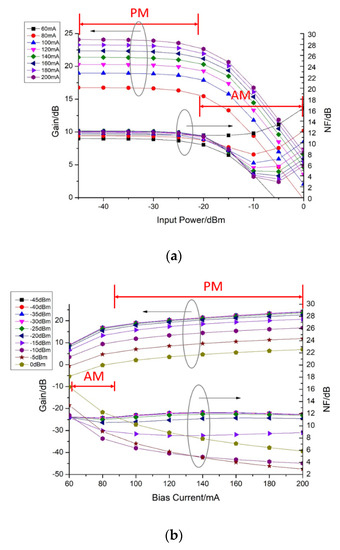
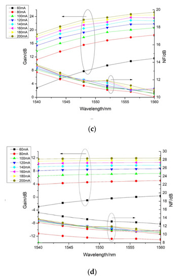
Figure 1.
Characteristic analysis diagram of an SOA: (a) Gain and NF with input power; (b) Gain and NF with bias current; (c,d) Gain and NF with wavelength (the left input power is −25 dBm, the right input power is −5 dBm).
The SOA consumes a spot of carriers at a low level of input power, which can fully amplify the optical signal. Therefore, the gain remains a constant substantially because the output power increases with the input power correspondingly. With the input power increases, the rate of carrier consumption caused by stimulated radiation increases, leading to a new balance of carrier concentration in the active region at a lower level. Accordingly, the gain of the SOA decreases with the reduction of the magnification ability. Under the gain-flat region, the NF remains the same at first since the stimulated and spontaneous radiation increase accordingly. Then, the NF decreases in that the output ASE decreases and the output OSNR increases under the gradual saturation of the SOA. Lastly, the NF rises with the decreases in the OSNR as a result of the intense gain saturation of the SOA.
Figure 1b depicts the influence of bias current on the characteristics of the SOA. The gain function is almost in linear ascent in the region of the bias current from 60 to 80 mA and nearly flat in the region between 80 mA and 200 mA. The NF with the input power from −15 dBm to −45 dBm is nearly flat and from 0 dBm to −15 dBm is almost linear in descent in the region of the bias current from 60 to 100 mA and nearly flat in the region between 100 mA and 200 mA. The bias current has nothing to do with NF approximately at low input power.
There is a little gain due to the low carrier concentration of the SOA, and there is a high NF since the low carrier concentration makes the stimulated radiation weaker at small bias current. As shown in Figure 1b, the gain increases monotonically at first and then maintains the same level as the bias current level—which is because the carrier density of the SOA increases, and the system is restrained by the recovery time of the carrier density. The increase in carrier concentration enhances the stimulated emission, which leads to the decrease in NF. Finally, NF remains stable with bias current since the stimulated radiation tends to be unaltered at the adequate bias current.
Figure 1c,d shows that the gain flatness of the SOA meets the standard between 1540 nm and 1560 nm. The output performance can basically meet the requirements of various applications, and different applications can be selected according to the performance of gain and NF in different operating regions, as summarized in Table 2.
Table 2.
Areas of operation for an SOA and its exploited performance for their application.
To sum up, we get the optimum operating point of the SOA. Under the circumstances where the bias current is 200 mA and the input power is −25 dBm or −5 dBm of the SOA, the output optical power can keep constant on the premise of ensuring low noise relatively. The input power of −25 dBm is suitable for phase modulation, while −5 dBm is suitable for amplitude modulation.
3. 10 Gb/s Bidirectional Transmission for a DFB-EAM-SOA-Based ONU
3.1. Design and Analysis
In order to analyze the quality of the signal transmission using DFB-EAM-SOA, we first tested the unidirectional transmission for both DS and US; then, we tested the bidirectional transmission under the optimal conditions we had gotten; finally, both ONUs were active and tested bidirectionally. In Figure 2, we propose a network schematic with 50 GHz channel spacing as in the International Telecommunication Union Telecommunication Standardization Sector (ITU-T) G.694.1 standard for DWDM [22,23]. The optical line terminal (OLT) is composed of several transceivers, and each transceiver corresponds to one ONU. The main parameters list of the simulation setting is shown in Table 3.
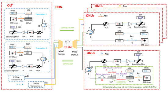
Figure 2.
The semiconductor optical amplifier electro−absorption modulator (SOA−EAM) − based optical network unit (ONU) for 10 Gb/s bidirectional transmission (ODN: optical distribution network; C1, C2: circulator; Mux/Demux: multiplexer/demultiplexer; VOA: variable optical attenuator; PIN: PIN−diode; TIA: trans−impedance amplifier).
Table 3.
Main parameters list of the simulation setting.
For DS transmission, the continuous wave light injected into the Mach–Zehnder modulator (MZM) employed at the OLT was modulated in non-return-to-zero (NRZ) format by a pseudo-random binary sequence (PRBS), which was generated by a distributed feedback (DFB) laser. The optical signals with different wavelengths were multiplexed and carried. After transmission over a 20 km standard single-mode fiber (SSMF), the signal was demultiplexed to different ONUs of corresponding wavelengths. The optical signal was converted into a low-noise electrical signal through a photoelectric detector and an equalizing filter. Finally, the bit error ratio (BER) was detected and analyzed.
For US transmission, an SOA-EAM was selected to improve the transmission distance of data signals because of its wide modulation bandwidth and low chirp, as depicted in the schematic view of Figure 2. There was leading edge distortion (as pre-distortion) to form an undershoot mode when data passed through the EAM, shown in the inset (I) of Figure 2, while the carrier recombination limitation in the SOA saturation led to the formation of an overshoot mode, as the inset (II) of Figure 2 shows; such mutually compensated optical processing can be adjusted by the bias point, and the whole system can emit an undistorted optical waveform (see the inset (III) of Figure 2) [18]. Additionally, the chirp from the absorption processing of an EAM can be compensated for by adjusting the negative frequency chirp from the carrier depletion of the SOA, which can reduce the chirp generated by the SOA-EAM and the dispersion effect in the optical transmission system [17]. The signal was detected at the OLT after a 20 km transmission.
3.2. Results and Discussion
Figure 3 shows the BER against the received power in unidirectional US and DS transmission. Figure 3a shows the BER characteristics with a signaling rate of 10 Gb/s in a unidirectional uplink. The horizontal axis shows the average received power. The amplitude shift keying (ASK) signal was generated with a peak-to-peak RF voltage of 2 V (VPP) for the EAM with a bias current of 80 mA (Ibias) for the SOA.
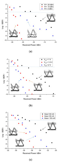
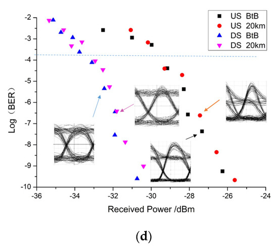
Figure 3.
The BER against the received power in a 10 Gb/s unidirectional transmission: (a) the upstream (US) BER curves for input power (Pi) values; (b) the US BER curves for the peak−to−peak RF voltage (VPP) values; (c) the US BER curves for the bias current (Ibias) values; (d) the US and downstream (DS) BER curves for back−to−back (BtB) and 20 km fibers.
At the FEC level of BER = 2.4 × 10⁻⁴ [20], the sensitivities reached −29.5 dBm, −27.5 dBm, and −21 dBm for input power (Pi) = −10 dBm, −5 dBm, and −20 dBm, respectively. There was a 2 dB power penalty between Pi = −10 dBm and −5 dBm, and an 8.5 dB power penalty between −10 dBm and −20 dBm. The eye diagrams are also shown in the insets of Figure 3a. The eye pattern at Pi = −20 dBm exhibits a thicker 1-level due to the OSNR degradation and at Pi = −10 dBm and −5 dBm shows the typical overshoot on account of the pattern effect [24].
We then modulated the EAM with VPP = 1 V, 1.5 V, and 2 V. The DFB laser provides an input power of −10 dBm, and there is Ibias = 80 mA, as previous. The BER against the received optical power is plotted in Figure 3b. At BER = 2.4 × 10⁻⁴, the received power sensitivities are −29.5 dBm, −28.4 dBm, and −25 dBm for VPP = 2 V, 1.5 V, and 1 V, respectively. Figure 3b also shows that the power penalties are 1.1 dB and 3.4 dB at BER = 2.4 × 10⁻⁴ when VPP decreases from 2 V to 1.5 V and from 1.5 V to 1 V, respectively. Figure 3c shows the measured BER with Ibias = 60 mA, 80 mA, and 100 mA at VPP = 2 V and Pi = −10 dBm, in which the EAM works under reverse bias and the SOA operates at forward bias. The sensitivities of −27 dBm, −29.5 dBm, and −29 dBm were obtained for Ibias = 60 mA, 80 mA, and 100 mA at BER of 2.4 × 10⁻⁴ for a 10 Gb/s signal with PRBS.
We show the BER curves of US and DS unidirectional transmissions in Figure 3d under the appropriate condition of Pi = −10 dBm, VPP = 2 V, and Ibias = 80 mA. At BER = 2.4 × 10⁻⁴ for the unidirectional US transmission, the sensitivities reached −29.8 dBm and −29.5 dBm for back-to-back (BtB) and 20 km fibers, respectively; in the DS direction, received sensitivities were −33.6 dBm and −33.3 dBm for BtB and 20 km fibers, respectively.
For bidirectional single-ONU and multi-ONU transmissions, the BER curves and eye diagrams with the optimal condition of Pi = −10 dBm, VPP = 2 V, and Ibias = 80 mA are shown in Figure 4. Figure 4a presents the US and DS received sensitivities of −29.5 dBm and −33.5 dBm for BtB transmission, and the sensitivities reach −28.9 dBm and −33.1 dBm after the 20 km fiber transmission at BER = 2.4 × 10⁻⁴ for 10 Gb/s. These are 0.3 dB and 0.6 dB larger than the unidirectional US transmission for BtB and 20 km fibers, respectively, and the penalty between BtB and 20 km fibers in bidirectional US transmission is 0.6 dB (0.3 larger than the unidirectional US transmission) due to backscattering and reflection effects in the bidirectional system [25].
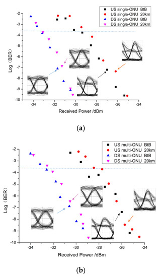
Figure 4.
The BER against the received power in 10 Gb/s bidirectional transmission: (a) single−ONU bidirectional transmission; (b) multi−ONU bidirectional transmission.
After accomplishing the bidirectional transmission of the single ONU, a neighboring ONU2 was added with 50 GHz spacing. The added ONU2 and transceiver2 used amplitude modulators, as shown in Figure 2. Compared with the single-ONU transmission, the multi-ONU transmission needed to consider the negative effect of crosstalk and cross-phase modulation between signals [26]. As Figure 4b shows, at BER = 2.4 × 10⁻⁴ for 10 Gb/s, for US, the sensitivities reach −28.8 dBm and −28.2 dBm for BtB and 20 km fibers, respectively; for DS, the received sensitivities are −33 dBm and −32.6 dBm for BtB and 20 km fibers, respectively. Compared with the bidirectional transmission in Figure 4a, there is a 0.7 dB and a 0.5 dB power penalty between the single-ONU and the multi-ONU in US and DS transmissions, respectively. It can be seen that the sensitivity penalty caused by the interference between multiple channels was less than 1 dB, so the influence of the neighboring ONU2 on ONU1 was not serious.
4. Conclusions
In this paper, we investigated an effective optimization of an SOA and an SOA-EAM in an NGPON2- ONU and analyzed their impacts on the system. The main characteristics of the SOA, namely the gain and NF, were obtained from the relationship between the bias current and the input power. The proper conditions of the SOA for phase and amplitude modulation were a bias current of 200 mA with an input power of −25 dBm and −5 dBm, respectively. We set up and analyzed the 10 Gb/s single-ONU and the multi-ONU bidirectional DWDM-PON based on an SOA-EAM. The results show that the sensitivities in 20 km US and DS transmissions reach −28.9 dBm and −33.1 dBm for the single-ONU and reach −28.2 dBm and −32.6 dBm for the multi-ONU at the BER of 2.4 × 10⁻⁴ with VPP = 2 V (Pi = −10 dBm, Ibias = 80 mA), respectively. As evidenced by their measured performance, such integration devices as SOAs and SOA-EAMs have the potential for low-cost use in metro-area network applications of NGPON2s.
Author Contributions
X.R.C. and G.Y.C. conceived and designed the experiments; X.R.C. performed the experiments; G.Y.C. supervised the project. All authors have read and agreed to the published version of the manuscript.
Funding
This research was funded by [the Natural Science Foundation of Jiangsu Province] grant number [BK20170199, BK20180598], [the Fundamental Research Funds for the Central Universities] grant number [JUSRP11835], [Postgraduate Research & Practice Innovation Program of Jiangsu Province] grant number [SJCX20_0762] And The APC was funded by [the Natural Science Foundation of Jiangsu Province] grant number [BK20170199].
Acknowledgments
This work was supported in part by the Jiangsu Provincial Research Center of Light Industrial Optoelectronic Engineering and Technology.
Conflicts of Interest
The authors declare that they have no known competing financial interests or personal relationships that could have appeared to influence the work reported in this paper.
References
- Luo, M.; Wu, D.; Li, W.; Zeng, T.; Zhou, L.; Meng, L.; Li, X.; Yu, S. 100 Gb/s (4 × 25 Gb/s) real-time coherent UDWDM-PON with a large power budget. IEEE/OSA J. Opt. Commun. Netw. 2019, 12, A204–A213. [Google Scholar] [CrossRef]
- Kim, K.O.; Doo, K.-H.; Lee, H.H.; Kim, S.H.; Park, H.; Oh, J.-Y.; Chung, H.S.; Doo, K.H. High Speed and Low Latency Passive Optical Network for 5G Wireless Systems. J. Light. Technol. 2019, 37, 2873–2882. [Google Scholar] [CrossRef]
- Presi, M.; Ciaramella, E. Mutual Seeding of Directly Modulated R-SOAs for Full-Duplex and Single-Wavelength Short Reaches. IEEE Photon. Technol. Lett. 2018, 30, 2064–2067. [Google Scholar] [CrossRef]
- Velásquez, J.C.; Tabares, J.; Prat, J. Differential 8-APSK monolithically integrated dual-EML transmitter for flexible coherent PONs. Opt. Lett. 2019, 44, 2760–2763. [Google Scholar] [CrossRef]
- Chu, G.Y.; Cano, I.; Brenot, R.; Debrégeas, H.; Prat, J.; Maho, A.; Polo, V. First demonstration and field trial on multi-user UDWDM-PON full duplex PSK-PSK with single monolithic integrated dual-output-DFB-SOA based ONUs. Opt. Lett. 2016, 41, 4696. [Google Scholar] [CrossRef]
- Chu, G.Y.; Cano, I.N.; Polo, V.; Kazmierski, C.; Brenot, R.; Prat, J. Monolithically Integrated Dual-Output DEML for Full Duplex DPSK-ASK and DPSK-SSB ONU in Ultra-Dense Channel Spaced Access Network. J. Light. Technol. 2016, 34, 2042–2048. [Google Scholar] [CrossRef]
- Ngo, M.N.; Poingt, F.; Brenot, R.; Nguyen, H.T.; Gosset, C.; Erasme, D.; Deniel, Q.; Genay, N.; Guillamet, R.; Lagay, N.; et al. ElectroAbsorption Modulated Laser Integrated with a Semiconductor Optical Amplifier for 100-km 10.3 Gb/s Dispersion-Penalty-Free Transmission. J. Light. Technol. 2013, 31, 232–238. [Google Scholar] [CrossRef]
- Reis, J.D.; Shukla, V.; Stauffer, D.R.; Gass, K. Technology Options for 400G Implementation. Optical Networking Forum (OIF) White Paper. Technical Report. July 2015. Available online: http://www.oiforum.com/wp-content/uploads/OIF-Tech-Options-400G-01.0.pdf (accessed on 1 April 2020).
- ITU-T Recommendation. G.989.2: 40-Gigabit-Capable Passive Optical Networks (NG-PON2): Physical Media Dependent (PMD) Layer Specification; ITU: Geneva, Switzerland, 2019. [Google Scholar]
- Niu, P.; Nablo, B.J.; Bhadriraju, K.; Reyes, D.R. Uncovering the Contribution of Microchannel Deformation to Impedance-Based Flow Rate Measurements. Anal. Chem. 2017, 89, 11372–11377. [Google Scholar] [CrossRef]
- Wang, N.; Kim, I.; Vassilieva, O.; Ikeuchi, T.; Wen, H.; Antonio-Lopez, J.E.; Alvarado-Zacarias, J.C.; Liu, H.; Fan, S.; Habib, S.; et al. Low-crosstalk few-mode EDFAs using retro-reflection for single-mode fiber trunk lines and networks. Opt. Express 2019, 27, 35962–35970. [Google Scholar] [CrossRef]
- Goki, P.N.; Imran, M.; Porzi, C.; Toccafondo, V.; Fresi, F.; Cavaliere, F.; Poti, L. Lossless WDM PON Photonic Integrated Receivers Including SOAs. Appl. Sci. 2019, 9, 2457. [Google Scholar] [CrossRef]
- Zhou, H.; Shen, Y.; Chen, M.; Fei, C.; He, J. Cost-efficient, polarization-insensitive and widely-tunable AOWC of OFDM signal based on FWM in SOA. Opt. Express 2019, 27, 38553–38566. [Google Scholar] [CrossRef] [PubMed]
- Kotb, A.; Zoiros, K.E.; Guo, C. Ultrafast performance of all-optical AND and OR logic operations at 160 Gb/s using photonic crystal semiconductor optical amplifier. Opt. Laser Technol. 2019, 119, 105611. [Google Scholar] [CrossRef]
- Melikyan, A.; Kaneda, N.; Kim, K.; Baeyens, Y.; Dong, P. Differential drive I/Q modulator based on silicon photonic electro-absorption modulators. J. Light. Technol. 2020, 38, 1. [Google Scholar] [CrossRef]
- Moreno, V.; Connelly, M.J.; Romero-Vivas, J.; Krzczanowicz, L.; Mora, J.; Muriel, M.A.; Capmany, J.; Galue, V.M. Integrated 16-ps Pulse Generator Based on a Reflective SOA-EAM for UWB Schemes. IEEE Photon. Technol. Lett. 2016, 28, 2180–2182. [Google Scholar] [CrossRef]
- Naughton, A.; Talli, G.; Porto, S.; Antony, C.; Ossieur, P.; Townsend, P.D. Design Optimization of R-EAM-SOA for Long-Reach Carrier-Distributed Passive Optical Networks. J. Light. Technol. 2014, 32, 4386–4392. [Google Scholar] [CrossRef]
- Wu, J.-P.; Ding, W.-Z.; Chiu, Y.-J. Low-Pattern-Dependence Prechirp Optical Modulation by Using Saturation Behaviors of SOA-Integrated EAM. J. Light. Technol. 2013, 31, 3651–3657. [Google Scholar] [CrossRef]
- Jeong, J.S.; Kim, H.-S.; Choi, B.-S.; Kim, D.C.; Kim, K.-S.; Park, M.-R.; Kwon, O.-K. Mitigation of Rayleigh crosstalk using noise suppression technique in 10-Gb/s REAM-SOA. Opt. Express 2012, 20, 26373–26378. [Google Scholar] [CrossRef]
- Shindo, T.; Fujiwara, N.; Kanazawa, S.; Nada, M.; Nakanishi, Y.; Yoshimatsu, T.; Kanda, A.; Chen, M.; Ohiso, Y.; Sano, K.; et al. High Power and High Speed SOA Assisted Extended Reach EADFB Laser (AXEL) for 53-Gbaud PAM4 Fiber-Amplifier-Less 60-km Optical Link. J. Light. Technol. 2020, 38, 2984–2991. [Google Scholar] [CrossRef]
- Sancho, J.; Lloret, J.; Gasulla, I.; Sales, S.; Capmany, J. Figures of merit for microwave photonic phase shifters based on semiconductor optical amplifiers. Opt. Express 2012, 20, 10519–10525. [Google Scholar] [CrossRef]
- Ruzbarsky, J.; Turan, J.; Ovsenik, L. Stimulated Brillouin scattering in DWDM all optical communication systems. In Proceedings of the 2016 26th International Conference Radioelektronika (RADIOELEKTRONIKA), Kosice, Slovakia, 19–20 April 2016; pp. 395–398. [Google Scholar]
- ITU-T Recommendation. G.694.1: Spectral Grids for WDM Applications: DWDM Frequency Grid; ITU: Geneva, Switzerland, 2002. [Google Scholar]
- Lee, D.-H.; Jeong, J.S.; Kim, K.-S.; Kim, H.-S.; Kim, D.C.; Park, M.-R.; Han, Y.-T.; Kwon, O.K.; Kwon, O.-K. Design and performance of 10-Gb/s L-band REAM-SOA for OLT Transmitter in next generation access networks. Opt. Express 2015, 23, 2339–2346. [Google Scholar] [CrossRef]
- Yeh, C.-H.; Jhao-Ren, C.; You, W.-Y.; Chow, C.W. Hybrid WDM FSO Fiber Access Network With Rayleigh Backscattering Noise Mitigation. IEEE Access 2020, 8, 96449–96454. [Google Scholar] [CrossRef]
- Ceballos-Herrera, D.E.; Lopez-Coyote, M.; Gutierrez-Castrejon, R. Crosstalk Characteristics of WDM Channels in Quasi-Homogeneous Multicore Fibers. IEEE Photon. Technol. Lett. 2020, 32, 759–762. [Google Scholar] [CrossRef]
Publisher’s Note: MDPI stays neutral with regard to jurisdictional claims in published maps and institutional affiliations. |
© 2020 by the authors. Licensee MDPI, Basel, Switzerland. This article is an open access article distributed under the terms and conditions of the Creative Commons Attribution (CC BY) license (http://creativecommons.org/licenses/by/4.0/).