An Analytical Model for Small Signal Stability Analysis in Unbalanced Electrical Power Systems
Abstract
1. Introduction
2. Description of the Stability Problem for Three-Phase Unbalanced Systems
- represents the state variables of the machines;
- represents the the algebraic variables of the system;
- represents the input variables, in this case the parameter associated with the control systems of the generators;
- represents the differential equations of the generators;
- represents the algebraic equations associated with the generators and traditional load flow equations;
- represent the number of state variables and algebraic equations.
- represents linearized state variables;
- represents linearized algebraic variables.
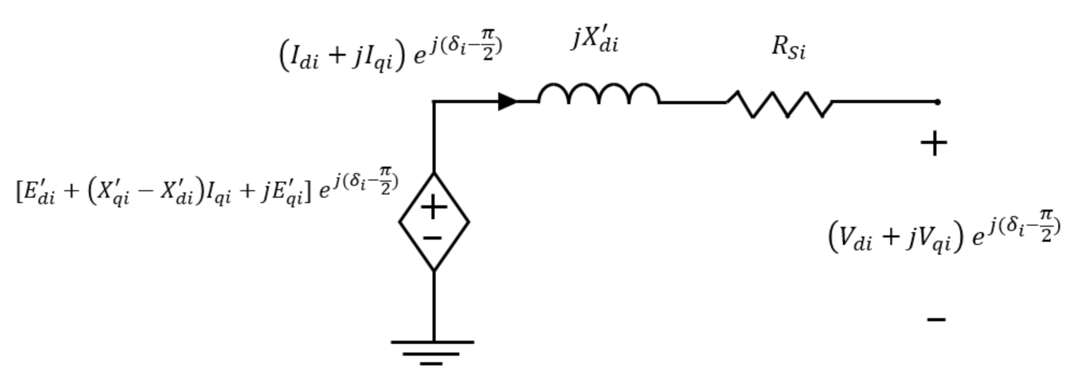
- Positive sequence: this is the real system considering that it operates in balanced conditions.
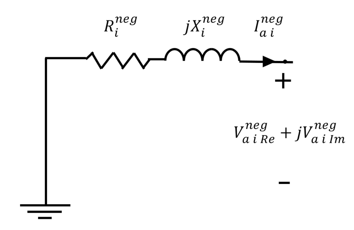
- Negative sequence: this has the same topology as the positive sequence, but the equivalent voltage sources of the generators are not represented.
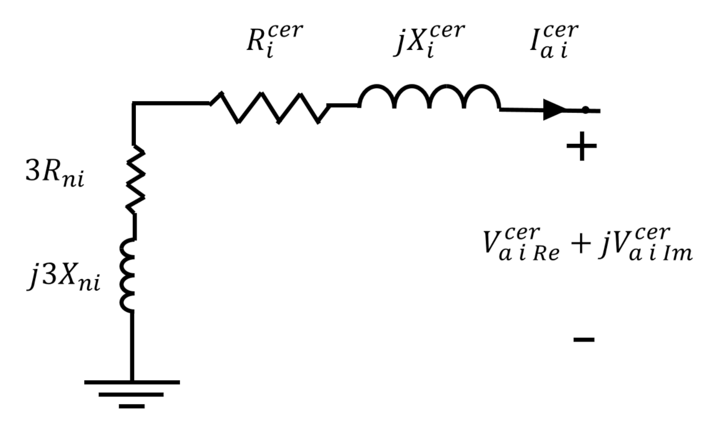
- Zero sequence: this has the same topology as the negative system, but only here, the grounding connection and the existence of neutrals are modeled.
- I is the identity matrix;
- represents the eigenvalue vector of the system (3).
- the damping ratio;
- the real part of the eigenvalue ;
- the real imaginary part of the eigenvalue .
3. Modeling and Linearization of the System
3.1. Modeling the Dynamics of the Machines
- the angular speed of the machine (rad/s);
- the synchronous speed of the machine (rad/s);
- the inertia constant (s);
- the machine damping (pu);
- the mechanical torque applied to the machine;
- the direct current and of quadrature (pu);
- the direct equivalent voltage and of quadrature (pu);
- the direct transitory reactance and of quadrature (pu);
- the current of the negative sequence, real and imaginary parts (pu);
- the resistance of the negative sequence (pu);
- the resistance of the machine stator (pu);
- the resistance of core losses due to unbalance (pu).
3.2. Internal Voltage And control Systems’ Differential Equations
- and the direct transient time constants and of quadrature (s);
- and the direct reactance and of quadrature (pu);
- and the transient direct reactance and of quadrature (pu);
- and the direct axis current and of quadrature (pu);
- the equivalent field voltage (pu).
- the reference voltage of the field control (pu);
- the gain of the voltage regulator;
- the time constant of the voltage regulator (s);
- the gain of the exciter;
- the time constant of the field voltage feedback (s);
- the regulator output;
- the non-linear function of the voltage regulator; for this case, .
- the internal variables of the PSS controller;
- the gain of the PSS controller;
- the time constants of the lead/lag blocks (s);
- the time constants of the washout block (s).
3.3. Stator Algebraic Equations
- the real part of the voltage phase sequence (pu);
- the real part of the current phase sequence (pu);
- the imaginary part of the voltage phase sequence (pu);
- the imaginary part of the current phase sequence (pu);
- the current gap of a phase (rad).
3.3.1. Positive Sequence
3.3.2. Negative Sequence
- the negative sequence resistance (pu);
- the negative sequence reactance (pu);
- the real part of the negative sequence voltage (pu);
- the imaginary part of the negative sequence voltage (pu);
3.3.3. Zero Sequence
- the zero sequence resistance (pu);
- the zero sequence reactance (pu);
- the neutral resistance (pu);
- the neutral reactance (pu);
- the real part of the zero sequence voltage (pu);
- the imaginary part of the zero sequence voltage (pu);
3.4. Network Equations
- the impedance element (pu);
- the admittance element (pu).
- the admittance between bus i and bus j between phase and phase (pu).
- Algebraic equations for a generation bus:
- Algebraic equations for a load bus:
3.5. Linearization
Summary of the Matrices’ Structures
4. Application Cases
4.1. Testing System and Modeling Methodology
- Scenario 1: balanced nominal charges;
- Scenario 2: charge increase by 45%.
4.2. Results
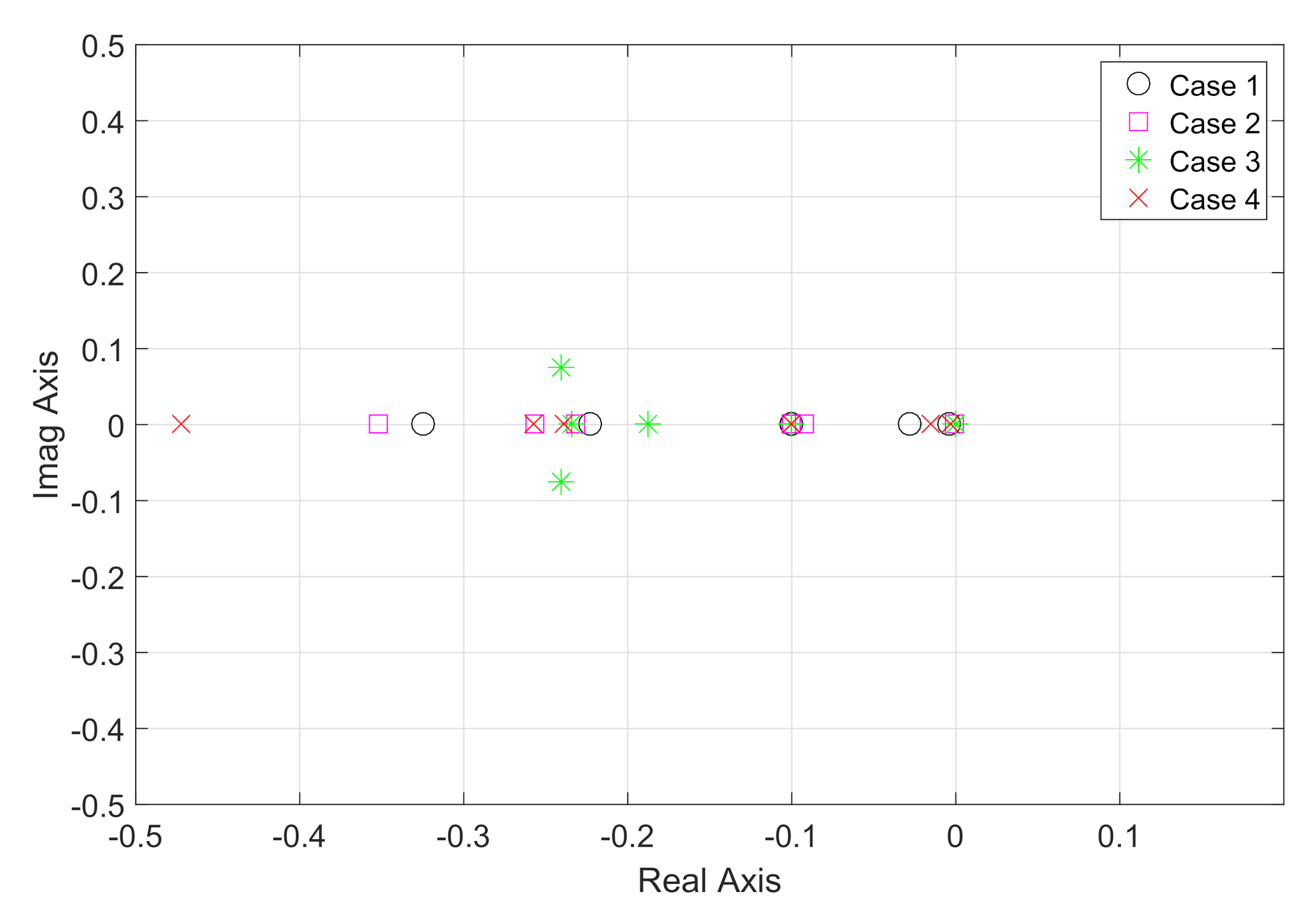
5. Conclusions
Author Contributions
Funding
Conflicts of Interest
Appendix A
Appendix A.1. Differential and Mechanic Equations
Appendix A.2. Stator Algebraic Equations
Appendix A.3. Network Equations
Appendix B
| 1 | 2 | 3 | 4 | 5 | 6 | 7 | 8 | 9 | |
|---|---|---|---|---|---|---|---|---|---|
| 1 | 0 | 0 | 0 | 0 | 0 | 0 | 0 | ||
| 2 | 0 | 0 | 0 | 0 | 0 | 0 | 0 | ||
| 3 | 0 | 0 | 0 | 0 | 0 | 0 | 0 | ||
| 4 | 0 | 0 | 0 | 0 | 0 | ||||
| 5 | 0 | 0 | 0 | 0 | 0 | 0 | |||
| 6 | 0 | 0 | 0 | 0 | 0 | 0 | |||
| 7 | 0 | 0 | 0 | 0 | 0 | ||||
| 8 | 0 | 0 | 0 | 0 | 0 | 0 | |||
| 9 | 0 | 0 | 0 | 0 | 0 | ||||
| Parameters | M/C1 | M/C 2 | M/C 3 |
|---|---|---|---|
| H (s) | 23.64 | 6.4 | 3.01 |
| (pu) | 0.146 | 0.8958 | 1.3125 |
| (pu) | 0.0608 | 0.1198 | 0.1813 |
| (pu) | 0.0969 | 0.8645 | 1.2578 |
| (pu) | 0.0969 | 0.1969 | 0.25 |
| (seg) | 8.96 | 6.0 | 5.89 |
| (seg) | 0.31 | 0.535 | 0.6 |
| D | 0 | 0 | 0 |
| Parameters | Machine 1 | Machine 2 | Machine 3 |
|---|---|---|---|
| 1 | 1 | 1 | |
| (seg) | 0.2 | 0.2 | 0.2 |
| 0.5 | 0.5 | 0.5 | |
| (seg) | 0.314 | 0.314 | 0.314 |
| 0.063 | 0.063 | 0.063 | |
| (seg) | 0.35 | 0.35 | 0.35 |
| Parameters | PSS 1 | PSS 2 | PSS 3 |
|---|---|---|---|
| 50 | 5 | 3 | |
| (seg) | 0.080373 | 0.08735 | 0.15 |
| (seg) | 0.0257 | 0.0236 | 0.01 |
| (seg) | 0.080373 | 0.08735 | 0.15 |
| (seg) | 0.0257 | 0.0236 | 0.01 |
| (seg) | 10 | 10 | 10 |
References
- Kundur, P.; Paserba, J.; Ajjarapu, V.; Andersson, G.; Bose, A.; Canizares, C.; Hatziargyriou, N.; Hill, D.; Stankovic, A.; Taylor, C.; et al. Definition and classification of power system stability. IEEE Trans. Power Syst. 2004, 19, 1387–1401. [Google Scholar] [CrossRef]
- Salim, R.; Ramos, R. A model-based approach for small signal stability assessment of unbalanced power systems. IEEE Trans. Power Syst. 2012, 27, 2006–2014. [Google Scholar] [CrossRef]
- Miao, Z.; Choudhry, M.; Klein, R. Dynamic simulation and stability control of three-phase power distribution system with distributed generators. In Proceedings of the 2002 IEEE Power Engineering Society Winter Meeting. Conference Proceedings (Cat. No. 02CH37309), New York, NY, USA, 27–31 January 2002; Volume 2, pp. 1029–1035. [Google Scholar]
- Xyngi, I.; Ishchenko, A.; Popov, M.; van der Sluis, L. Transient stability analysis of a distribution network with distributed generators. IEEE Trans. Power Syst. 2009, 24, 1102–1104. [Google Scholar] [CrossRef]
- Spitsa, V.; Salcedo, R.; Ran, X.; Martinez, J.F.; Uosef, R.E.; De Leon, F.; Czarkowski, D.; Zabar, Z. Three–phase time–domain simulation of very large distribution networks. IEEE Trans. Power Deliv. 2012, 27, 677–687. [Google Scholar] [CrossRef]
- Jain, H.; Parchure, A.; Broadwater, R.P.; Dilek, M.; Woyak, J. Three-phase dynamic simulation of power systems using combined transmission and distribution system models. IEEE Trans. Power Syst. 2016, 31, 4517–4524. [Google Scholar] [CrossRef]
- Salim, R.H.; Ramos, R.A. A framework for analyzing the small signal dynamic performance of unbalanced power systems. IEEE Power Energy Soc. Gen. Meet. 2011, 1–8. [Google Scholar] [CrossRef]
- Sun, J. Small-signal methods for AC distributed power systems-A review. IEEE Trans. Power Electron. 2009, 24, 2545–2554. [Google Scholar] [CrossRef]
- Khazaei, J.; Miao, Z.; Piyasinghe, L.; Fan, L. Initialization of unbalanced radial distribution systems for small signal stability analysis. IEEE Power Energy Soc. Gen. Meet. 2015, 1–5. [Google Scholar] [CrossRef]
- Nasr-Azadani, E.; Canizares, C.A.; Olivares, D.E.; Bhattacharya, K. Stability analysis of unbalanced distribution systems with synchronous machine and DFIG based distributed generators. IEEE Trans. Smart Grid 2014, 5, 2326–2338. [Google Scholar] [CrossRef]
- Azadani, E.N.; Canizares, C.; Bhattacharya, K. Modeling and stability analysis of distributed generation. In Proceedings of the 2012 IEEE Power and Energy Society General Meeting, San Diego, CA, USA, 22–26 July 2012; pp. 1–8. [Google Scholar]
- Wen, B.; Boroyevich, D.; Burgos, R.; Mattavelli, P.; Shen, Z. Small-Signal Stability Analysis of Three-Phase AC Systems in the Presence of Constant Power Loads Based on Measured d-q Frame Impedances. IEEE Trans. Power Electron. 2015, 30, 5952–5963. [Google Scholar] [CrossRef]
- Mortazavian, S.; Shabestary, M.M.; Mohamed, Y.A.R.I. Analysis and Dynamic Performance Improvement of Grid-Connected Voltage-Source Converters under Unbalanced Network Conditions. IEEE Trans. Power Electron. 2017, 32, 8134–8149. [Google Scholar] [CrossRef]
- Karami, E.; Gharehpetian, G.B.; Madrigal, M.; De Jesus Chavez, J. Dynamic phasor-based analysis of unbalanced three-phase systems in presence of harmonic distortion. IEEE Trans. Power Syst. 2018, 33, 6642–6654. [Google Scholar] [CrossRef]
- Miao, Z.; Piyasinghe, L.; Khazaei, J.; Fan, L. Dynamic Phasor-Based Modeling of Unbalanced Radial Distribution Systems. IEEE Trans. Power Syst. 2015, 3, 3102–3109. [Google Scholar] [CrossRef]
- Ojo, Y.; Schiffer, J. Towards a time-domain modeling framework for small signal analysis of unbalanced microgrids. In Proceedings of the 2017 IEEE Manchester PowerTech, Manchester, UK, 18–22 June 2017; pp. 1–6. [Google Scholar] [CrossRef]
- GmbH, D. DigSilent PowerFactory 2019 User Manual; McGraw-Hill: New York, NY, USA, 2018. [Google Scholar]
- Sauer, P.W.; Chow, J.H. Power System Dynamics And Stability, 2nd ed.; Wiley: Hoboken, NJ, USA, 2007. [Google Scholar]


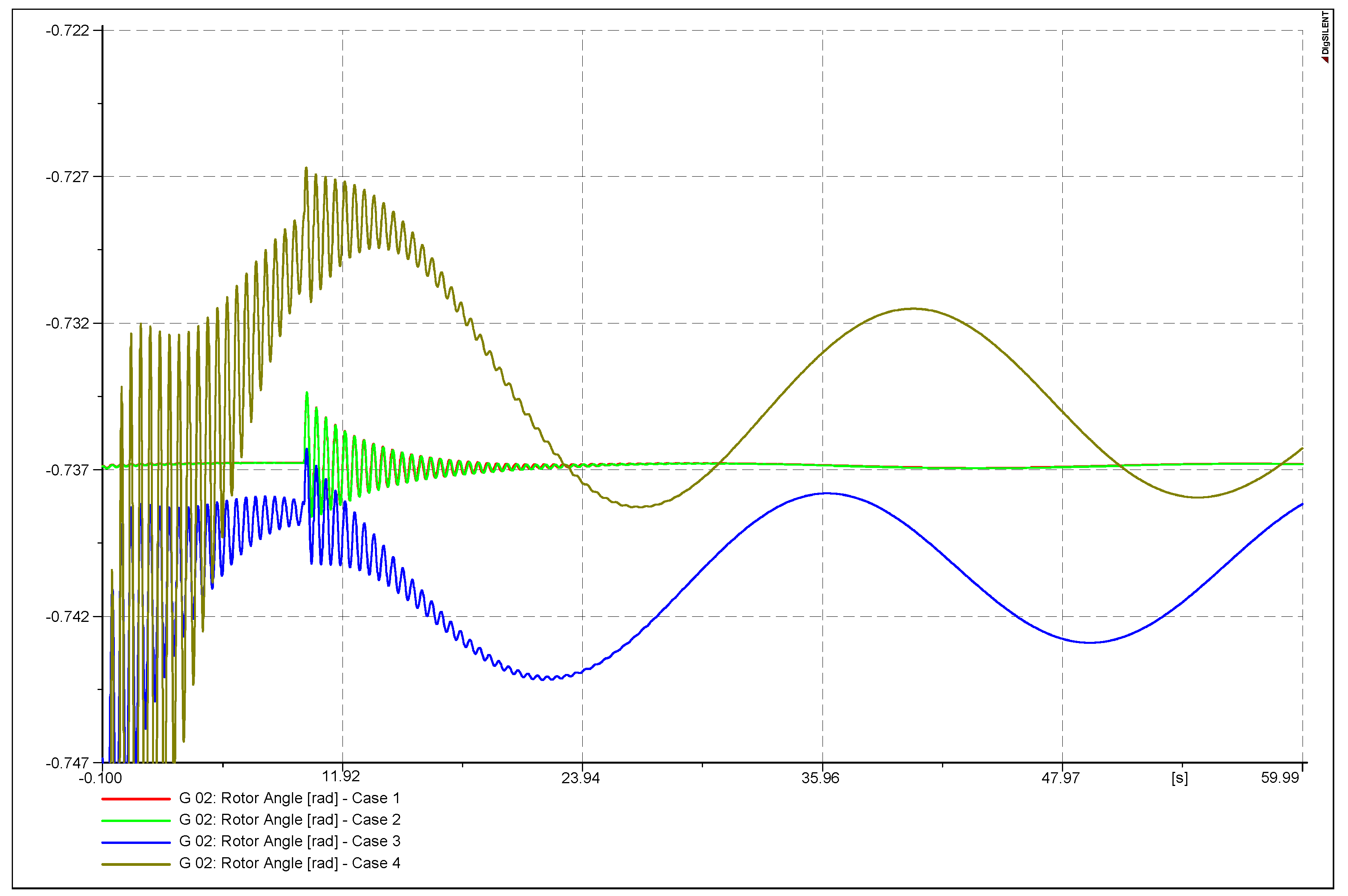
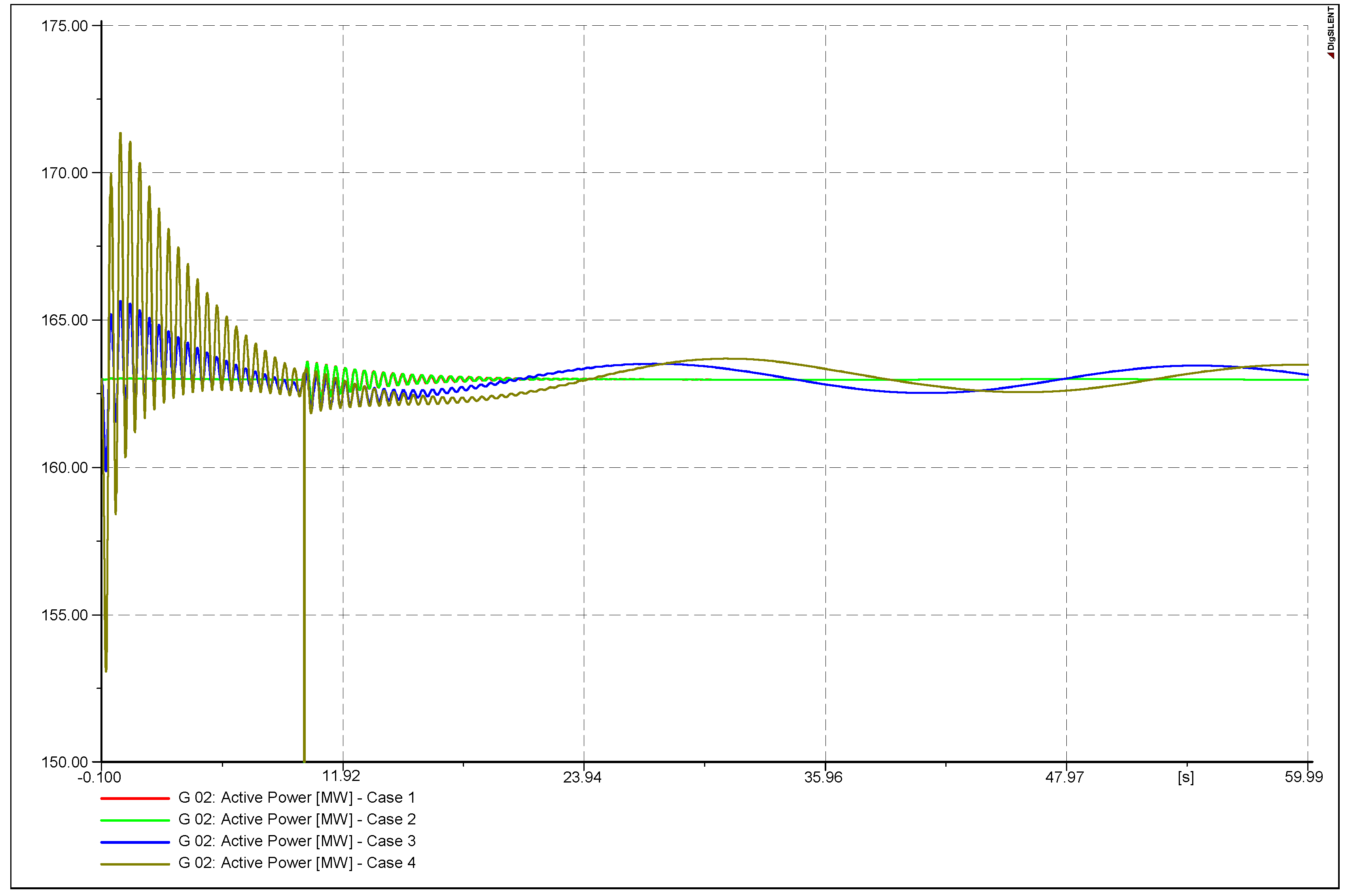
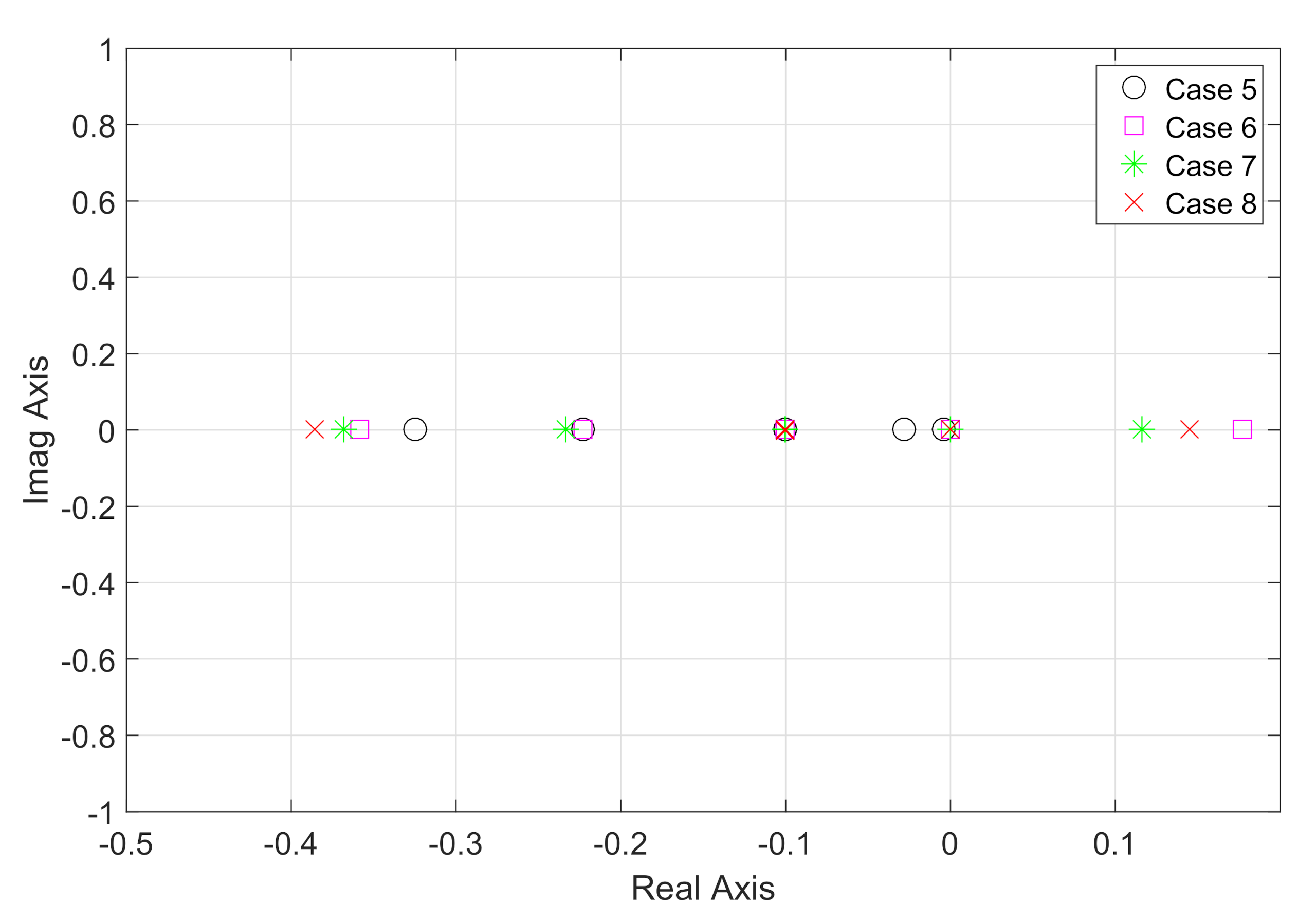

| Loads | Percentage | ||
|---|---|---|---|
| Phase A | Phase B | Phase C | |
| Load A | 33.3% | 33.3% | 33.3% |
| Load B | 33.3% | 33.3% | 33.3% |
| Load C | 33.3% | 33.3% | 33.3% |
| Loads | Percentage | ||
|---|---|---|---|
| Phase A | Phase B | Phase C | |
| Load A | 25% | 45% | 30% |
| Load B | 45% | 30% | 25% |
| Load C | 30% | 25% | 45% |
| Loads | Percentage | ||
|---|---|---|---|
| Phase A | Phase B | Phase C | |
| Load A | 60% | 20% | 20% |
| Load B | 20% | 60% | 20% |
| Load C | 20% | 20% | 60% |
| Study Cases | Scenario 1 | Scenario 2 |
|---|---|---|
| Balanced model | Case 1 | Case 5 |
| Unbalanced model with balanced initial conditions | Case 2 | Case 6 |
| Unbalanced model with unbalanced initial conditions, Form A | Case 3 | Case 7 |
| Unbalanced model with unbalanced initial conditions, Form B | Case 4 | Case 8 |
| Case 1 | Case 2 | ||
| Eigenvalues | Damping Ratio (%) | Eigenvalues | Damping Ratio (%) |
| −100.0009 ± 0.3054369i | 99.9995 | −100.0009 ± 0.3003607i | 99.9995 |
| −42.3732 ± 0.14653i | 42.3726 | −42.3732 ± 0.142034i | 42.3726 |
| −38.9105 ± 0.0263457i | 38.9100 | −38.9176 | 38.9171 |
| −1.40217 ± 15.5444i | 1.4021 | −38.9034 | 38.9029 |
| −1.27155 ± 11.9067i | 1.2715 | −1.44819 ± 15.5344i | 1.4482 |
| −5.3496 | 5.3495 | −1.38837 ± 11.6824i | 1.3884 |
| −4.3335 ± 1.8916i | 4.3335 | −5.2860 | 5.2859 |
| −4.2087 ± 1.7191i | 4.2087 | −4.3415 ± 1.8916i | 4.3414 |
| −4.2254 ± 1.7825i | 4.2253 | −4.2089 ± 1.7175i | 4.2089 |
| −3.1150 | 3.1149 | −4.2353 ± 1.7843i | 4.2353 |
| −1.4544 | 1.4544 | −2.7744 | 2.7744 |
| −1.2892 | 1.2892 | −1.4487 | 1.4487 |
| −1.0111 | 1.0111 | −1.2865 | 1.2865 |
| −0.0005 | 0.0005 | −0.9329 | 0.9329 |
| −0.24096 ± 0.075553i | 0.2410 | −0.4723 | 0.4723 |
| −0.1878 | 0.1878 | −0.0032 | 0.0032 |
| −0.2340 | 0.2340 | −0.0155 | 0.0155 |
| −0.1002 | 0.1002 | −0.2577 | 0.2577 |
| −0.1002 | 0.1002 | −0.2391 | 0.2391 |
| −3.2258 | 3.2258 | −0.1002 | 0.1002 |
| −0.1002 | 0.1002 | ||
| −3.2258 | 3.2258 | ||
| Case 3 | Case 4 | ||
| Eigenvalues | Damping Ratio (%) | Eigenvalues | Damping Ratio (%) |
| −100.0009 ± 0.3054369i | 99.9995 | −100.0009 ± 0.3003607i | 99.9995 |
| −42.3732 ± 0.14653i | 42.3726 | −42.3732 ± 0.142034i | 42.3726 |
| −38.9105 ± 0.0263457i | 38.9100 | −38.9176 | 38.9171 |
| −1.40217 ± 15.5444i | 1.4021 | −38.9034 | 38.9029 |
| −1.27155 ± 11.9067i | 1.2715 | −1.44819 ± 15.5344i | 1.4482 |
| −5.3496 | 5.3495 | −1.38837 ± 11.6824i | 1.3884 |
| −4.3335 ± 1.8916i | 4.3335 | −5.2860 | 5.2859 |
| −4.2087 ± 1.7191i | 4.2087 | −4.3415 ± 1.8916i | 4.3414 |
| −4.2254 ± 1.7825i | 4.2253 | −4.2089 ± 1.7175i | 4.2089 |
| −3.1150 | 3.1149 | −4.2353 ± 1.7843i | 4.2353 |
| −1.4544 | 1.4544 | −2.7744 | 2.7744 |
| −1.2892 | 1.2892 | −1.4487 | 1.4487 |
| −1.0111 | 1.0111 | −1.2865 | 1.2865 |
| −0.0005 | 0.0005 | −0.9329 | 0.9329 |
| −0.24096 ± 0.075553i | 0.2410 | −0.4723 | 0.4723 |
| −0.1878 | 0.1878 | −0.0032 | 0.0032 |
| −0.2340 | 0.2340 | −0.0155 | 0.0155 |
| −0.1002 | 0.1002 | −0.2577 | 0.2577 |
| −0.1002 | 0.1002 | −0.2391 | 0.2391 |
| −3.2258 | 3.2258 | −0.1002 | 0.1002 |
| −0.1002 | 0.1002 | ||
| −3.2258 | 3.2258 | ||
| Case 5 | Case 6 | ||
| Eigenvalues | Damping Ratio (%) | Eigenvalues | Damping Ratio (%) |
| −100.0005 ± 0.2310944i | 99.9997 | −100.0007 ± 0.2700379i | 99.9996 |
| −42.3731 ± 0.114598i | 42.3728 | −42.3731 ± 0.129702i | 42.3727 |
| −38.9105 ± 0.0353774i | 38.9102 | −38.9583 | 38.9579 |
| −0.838697 ± 12.7151i | 0.8387 | −38.8626 | 38.8622 |
| −0.20069 ± 8.3749i | 0.2007 | −1.6603 ± 15.7714i | 1.6603 |
| −4.9831 | 4.9830 | −1.59423 ± 12.0215i | 1.5942 |
| −4.3417 ± 1.8695i | 4.3417 | −4.7451 | 4.7450 |
| −4.2221 ± 1.7196i | 4.2221 | −4.4188 ± 1.9184i | 4.4187 |
| −4.2777 ± 1.8013i | 4.2777 | −4.2204 ± 1.7038i | 4.2203 |
| −3.3397 | 3.3397 | −4.294 ± 1.8199i | 4.2940 |
| −1.3942 | 1.3941 | −2.0724 | 2.0724 |
| −1.2578 | 1.2578 | −1.4928 | 1.4928 |
| −0.7910 | 0.7910 | −0.78907 ± 0.3786i | 0.7891 |
| −0.5069 | 0.5069 | −1.2080 | 1.2080 |
| −0.3246 | 0.3246 | 0.1771 | −0.1771 |
| −0.2232 | 0.2232 | 0.0002 | −0.0002 |
| −0.0045 | 0.0045 | −0.3588 | 0.3588 |
| −0.0282 | 0.0282 | −0.2231 | 0.2231 |
| −0.1003 | 0.1003 | −0.1001 | 0.1001 |
| −0.1001 | 0.1001 | −0.1001 | 0.1001 |
| −3.2258 | 3.2258 | −3.2258 | 3.2258 |
| Case 7 | Case 8 | ||
| Eigenvalues | Damping Ratio (%) | Eigenvalues | Damping Ratio (%) |
| −100.0007 ± 0.2706928i | 99.9996 | −100.0006 ± 0.248591i | 99.9997 |
| −42.3732 ± 0.132069i | 42.3727 | −42.3731 ± 0.106511i | 42.3727 |
| −38.9450 | 38.9446 | −39.0035 | 39.0031 |
| −38.8759 | 38.8755 | −38.8172 | 38.8169 |
| −1.66024 ± 15.7902i | 1.6602 | −1.76227 ± 15.8307i | 1.7623 |
| −1.54966 ± 12.1486i | 1.5496 | −2.05173 ± 11.6027i | 2.0517 |
| −4.7810 | 4.7809 | −4.5189 | 4.5189 |
| −4.4198 ± 1.9231i | 4.4198 | −4.4769 ± 1.9239i | 4.4768 |
| −4.2206 ± 1.7084i | 4.2206 | −4.2252 ± 1.686i | 4.2251 |
| −4.2954 ± 1.8199i | 4.2954 | −4.3212 ± 1.8441i | 4.3212 |
| −2.1211 | 2.1211 | 0.6634 | −0.6634 |
| −1.5075 | 1.5075 | −1.8076 | 1.8076 |
| −1.2391 | 1.2391 | −1.4787 | 1.4787 |
| −0.76142 ± 0.27743i | 0.7614 | −0.80976 ± 0.61076i | 0.8098 |
| 0.1164 | −0.1164 | −0.8088 | 0.8088 |
| 0.0003 | −0.0003 | −0.3860 | 0.3860 |
| −0.3678 | 0.3678 | 0.1447 | −0.1447 |
| −0.2336 | 0.2336 | 0.0001 | −0.0001 |
| −0.1001 | 0.1001 | −0.1001 ± 1.5159 × i | 0.1001 |
| −0.1001 | 0.1001 | −3.2258 | 3.2258 |
| −3.2258 | 3.2258 | ||
Publisher’s Note: MDPI stays neutral with regard to jurisdictional claims in published maps and institutional affiliations. |
© 2020 by the authors. Licensee MDPI, Basel, Switzerland. This article is an open access article distributed under the terms and conditions of the Creative Commons Attribution (CC BY) license (http://creativecommons.org/licenses/by/4.0/).
Share and Cite
Verdejo, H.; Moreira, P.; Kliemann, W.; Becker, C.; Delpiano, J. An Analytical Model for Small Signal Stability Analysis in Unbalanced Electrical Power Systems. Appl. Sci. 2020, 10, 8855. https://doi.org/10.3390/app10248855
Verdejo H, Moreira P, Kliemann W, Becker C, Delpiano J. An Analytical Model for Small Signal Stability Analysis in Unbalanced Electrical Power Systems. Applied Sciences. 2020; 10(24):8855. https://doi.org/10.3390/app10248855
Chicago/Turabian StyleVerdejo, Humberto, Pablo Moreira, Wolfgang Kliemann, Cristhian Becker, and José Delpiano. 2020. "An Analytical Model for Small Signal Stability Analysis in Unbalanced Electrical Power Systems" Applied Sciences 10, no. 24: 8855. https://doi.org/10.3390/app10248855
APA StyleVerdejo, H., Moreira, P., Kliemann, W., Becker, C., & Delpiano, J. (2020). An Analytical Model for Small Signal Stability Analysis in Unbalanced Electrical Power Systems. Applied Sciences, 10(24), 8855. https://doi.org/10.3390/app10248855


