Article

Dynamic Response of Drill Floor Considering Propagation of Blast Pressure Subsequent to Blowout

1
Department of Structure Basic Design, Samsung Heavy Industries, Geoje 53261, Korea
2
Department of Naval Architecture and Ocean Engineering, Pusan National University, Busan 46241, Korea
*
Author to whom correspondence should be addressed.
Appl. Sci. 2020, 10(24), 8841; https://doi.org/10.3390/app10248841
Submission received: 30 October 2020 / Revised: 3 December 2020 / Accepted: 3 December 2020 / Published: 10 December 2020
(This article belongs to the Section Marine Science and Engineering)

Abstract

:

Featured Application

Precise estimation of blast loading to drilling unit in offshore facilities.

Abstract

Explosions and fire have very critical safety hazard impacts on offshore oil and gas facilities since they are mostly located in remote areas and could induce serious environmental issues. Explosion risk assessment and structure blast analysis are essential for these production facilities, and research studies have been carried out. Explosion due to blowout during drilling operation is also a critical risk for drilling units, and this has not been researched much until the accident of the drilling unit in the Gulf of Mexico in 2010. This paper provides the risk and evaluation of explosion and structure under blast pressure during the drilling operation, whereas previous research studies have mainly been interested in process plants. This study suggests weight saving in drilling units through the consideration of the actual behavior of gas explosion. Weight saving is the priority of offshore unit design due to payload. This research also gives guidelines to select the material-grade-appropriate anti-explosion system through the comparison of several materials by design and result.

1. Introduction

Research studies have been carried out on fires and explosions caused by oil and gas leakage in Floating Production Storage Offloading (FPSO) as an offshore facility [1,2,3,4,5]. The drilling operation is essential for oil and gas production, and there are risks from accidental blowout as well as from induced fire and explosion. The key function of a drill floor is to hold the drilling equipment and to support derrick and drilling operating loads. However, only a few studies on explosions and fire related to drilling have been reported [6], and no observations of the structural response of the drilling unit have been made when experiencing an explosion. This is the reason why this study focuses on the drill floor. This study contributes to the investigation of the structure response of the drill floor of a drilling unit and suggests a new approach for blast pressure application based on the observation of blast pressure propagation. The drill pipe is connected to the drill hole in a seabed from the top drive on a drill floor, and the oil and gas mixture can be blown out in the case of failure in the Blowout Preventer (BOP) system during drilling operation. Leakage of oil and gas mixture is expected in the connections over and under the drill floor; therefore, structural integrity of the drill floor is critical for the entire facility when it experiences an accident. Quantitative risk analysis of oil and gas drilling has been introduced based on Risk Influence Factors (RIFs) and Human and Organizational Factors (HOFs) for the Deepwater Horizon blowout case [7]. Several safety barrier models were illustrated to mitigate and control the blowout accident, and event tree analysis was used to analyze the possible consequence chains [8]. The blast wave propagation of an explosive detonation can cause disastrous damage on various structures, and the computed results were found to be in agreement with the theoretical and experimental data [9]. Simplified blast pressure estimation is not sufficient to describe the explosion and blast wave propagation in complex facilities. The use of Computational Fluid Dynamics (CFD) for blast wave predictions present a more precise estimation of the energy and resulting pressure of the blast wave, and provides the ability to evaluate non-symmetrical effects caused by realistic geometries, gas cloud variations, and ignition locations; however, the main challenge in applying CFD is that these models require more information about the actual facility, including geometry details and process information [10]. This study fully reflects the geometry and process information of a typical drilling facility. A combined blast pressure approach was presented for a case in which the design blast pressure was specified for engineering purposes using Flame Acceleration Simulator (FLACS) software. This showed that the global blast pressure could result in an overly conservative design, if the maximum explosion loads on each item are summed simultaneously [11]. This approach is quite practical to use in the design and engineering of each component of oil and gas facilities, such as the structure, piping, and electricals; however, this approach considers that blast pressure effects on all facilities at the same time regardless of the distance from each facilities to a location of the ignition. The relationships between blast pressure and impulse of FPSO topside blast walls has been developed and a practical procedure for nonlinear structural response analysis of FPSO topside blast wall under explosion loads was introduced. One was computed using time-domain nonlinear finite element analysis, while the other was performed using a single degree of the freedom method based on resistance function. Direct application of blast pressure from CFD analysis through a consequence exceedance curve has been introduced [12,13]. In order to apply blast pressure effectively, a combined application of blast pressure was carried out [14], and an improvement and alleviation method for structures against blast pressure was proposed [15,16].
The blast pressure induced by an explosion propagates to the area within a short time, and the pressure level increases as the explosion develops from the ignition point. Several applications of blast pressure are compared. A more realistic and effective method for reducing the weight of the structure is introduced. Many research studies on the production units such as FPSO were carried out compared to the drilling unit. However, the consequences of the accident of both offshore units are critical in view of the disaster of the Deepwater Horizon rig. Especially drill floors of drilling unit are packed with drilling equipment and directly affected by accidents such as fire and explosion. Fire and explosion of drill floor has not been studied enough. This evaluation is essential for the safety assessment of drill floors and drilling units.

2. Drill Floor Design and Risk Assessment for Gas Explosion

2.1. General Information and Design Procedure for Drill Floor

The drill floor is generally located in the middle of a drillship or drill rig due to minimize motion during the drilling operation. It primarily consists of a main deck supported on four cruciform columns and eight supporting diagonal box girders. Another type consists of four rigid box girder columns to support the drill floor. The decks of drill ships and drill rigs support the columns of the drill floor and are reinforced to resist the force during operation. On the drill floor module, there is various equipment such as a rotary table, eight matched pairs of riser tensioner, drawworks, winches, derrick, BOP sea fixing, X-mas crane, etc. The mud module stores and provides mud to the drilling systems, and risers are stacked in the riser deck. Several tests of oil and gas reservoir are carried out during the drilling operation in a well test area. Figure 1 shows the general arrangement of the drilling unit explained above.
Table 1 presents the drill floor weight and the weight distribution in analysis, respectively. This weight is assumed based on a previously conducted project data. The weight of the drill floor is adopted in -finite element (FE) analysis with factorization to meet the total weight.
For structural analysis, FE modeling mass (1372 ton) of drill floor is adjusted to actual mass (4000 ton) by multiplying the gravity factor (2.915).
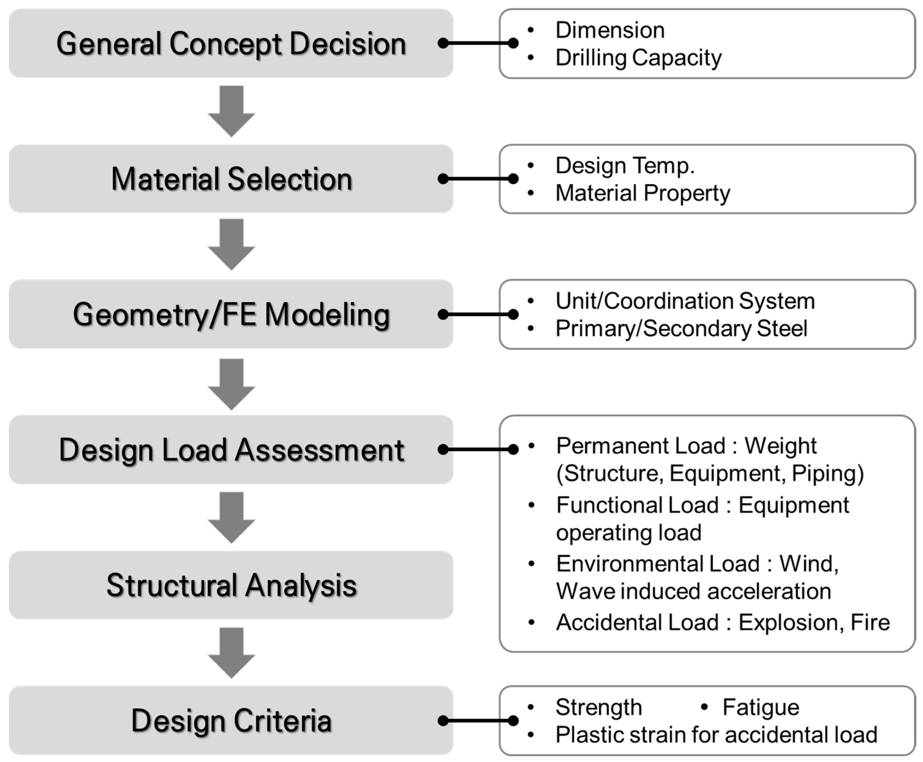
Figure 2 shows the general drill floor design flow chart. The overall dimension of the drill floor is determined by the drilling capacity and the general arrangement of the drilling facility. High tensile strength steel is preferred for use in the drill floor structure since it sustains heavy drilling load and equipment. The design temperature is also an important factor for choosing the material grade. Once the dimension and material are determined, the detailed geometry is created, and FE modeling is performed. Assessment of the design load involves many loadings on the drill floor. They include a combination of permanent, variable, functional, environmental, and accidental loads. The structural analysis is carried out by linear and non-linear analyses. These analysis outputs are investigated to meet the drill floor design criteria. If it meets the criteria, the design process is terminated, otherwise some improvement in the steel structure design such as reinforcement is to be considered.

2.2. Gas Explosion Risk Assessment and Management

Figure 3 shows the general drill floor design against blast load and the proposed methodology for blast load application. Explosion scenarios are set up based on wind and gas properties, blowout characteristics, and ignition locations. Consequence analysis includes gas dispersion analysis and explosion analysis. These analyses are carried out for each blowout and ignition scenario, and the gas volume and blast pressure time history are obtained for each scenario. FLACS program is used in this study for gas dispersion and explosion analysis. The probability of each explosion scenario is obtained from the event tree and calculations. The exceedance curve is obtained from these probabilities and blast pressures. Generally, a certain probability level, as well as its corresponding pressure, is selected as the design pressure to avoid a too conservative actual design. This study uses the consequence level of blast pressure since the comparison and investigation of each pressure application is the main focus. Moreover, this study considers the characteristics of propagation of blast load in order to reflect the real nature of gas explosion and avoid obtaining a too conservative design for the anti-blast structure. Detailed blowout scenarios and assumptions are described in Section 3.

2.3. The Contribution of This Study to Drill Floor Design for Blast Load

This study considers the characteristics of propagation of blast load in order to reflect the real nature of gas explosion and avoid obtaining a too conservative design for the anti-blast structure.

3. Blowout Explosion Analysis

Blowout in an oil and gas drilling facility means an uncontrolled flow of gas, oil, or other fluids from the reservoir, i.e., loss of 1. barrier (i.e., hydrostatic head) or leak and loss of 2. barrier, i.e., (BOP/Downhole Safety Valve) [18]. This chapter describes the blowout scenarios that could occur during the drilling operation. Based on the scenario, dispersion and explosion analysis is carried out to use as input to the structural analysis of the drill floor.

3.1. FLACS Program

Explosion simulation was carried out using FLACS program. FLACS is a finite volume solver that solves the Reynolds averaged mass, momentum, and energy balance equations, with special schemes for supersonic flows and a database of chemical kinetics [19].
There are several approaches to analyze explosion such as the Smoothed Partial Hydrodynamic (SPH) Method, Boundary Element Method (BEM) and Finite Volume Method (FVM). These methodologies are reviewed, and a validity check has been carried out [20]. This study utilizes FLACS which adopts FVM, since it is widely used and accepted for explosion analysis in offshore projects and petroleum industries.
Followings describe the mathematical model for compressible fluid flow used in FLACS. Conservation principles have been applied to the following quantities in order to derive the conservation equations [21,22]:
  • Mass;
  • Momentum;
  • Enthalpy;
  • Mass fraction of fuel (or products);
  • Mixture fraction;
  • Turbulent kinetic energy;
  • Dissipation rate of turbulent kinetic energy.
The equation of state is that of an ideal gas, and is presented in Equation (1):
pW =   ρ RT  
where p is absolute pressure, W is the molar weight of the gas mixture, ρ is density, R is the universal gas coefficient and T is absolute temperature.
Conservation of mass (2):
t ( β v ρ ) +   x j ( β j ρ u j ) =   m ˙ / V  
where β v is volume porosity, β j is area porosity in j-direction, u j is mean velocity component in j-direction, m ˙ is mass rate and V is volume.
The conservation of momentum (3) secures that the relation between pressure and flow velocities is representative.
t ( β v ρ u i ) + x j ( β j ρ u j u i ) = β v p x i +   x j ( β j σ i j ) + R i + R w + β v ( ρ ρ 0 ) g i
where R i   represents flow resistance in i-direction due to obstruction, R w is flow resistance due to wall, σ i j is stress tensor and gi is gravitational acceleration in i-direction (4) and (5).
R i = f i A i ρ | u i | u i  
A i = 1 β i x i
and f i is a non-dimensional constant depending on type and orientation of the obstruction.
Conservation of enthalpy (6):
t ( β v ρ h ) + x j ( β j ρ u j h ) = x j ( β j μ e f f σ h h x j ) + β v D p D t + Q ˙
where h is enthalpy, μ e f f is effective viscosity, and Q ˙ is heat flow rate.
Conservation of fuel mass fraction (7):
t ( β v ρ Y fuel ) + x j ( β j ρ u j Y fuel ) = x j ( β j μ e f f σ f u e l Y fuel x j ) + R fuel
where Y fuel is mass fraction and R fuel is reaction rate for fuel.
Conservation of mixture fraction (8):
t ( β v ρ f ) + x j ( β j ρ u j f ) = x j ( β j μ e f f σ f f x j )
where f is mixture fraction.
The turbulence equation includes conservation of turbulent kinetic energy (9):
t ( β v ρ k ) + x j ( β j ρ u j k ) = x j ( β j μ e f f σ k k x j ) + P k β v ρ ε
where k is turbulent kinetic energy, P k is production rate of turbulent kinetic energy, and ε is dissipation rate of turbulent energy.
Conservation of dissipation rate of turbulent kinetic energy (10):
t ( β v ρ ε ) + x j ( β j ρ u j ε ) = x j ( β j μ e f f σ ε ε x j ) + P ε C 2 β v ρ ε 2 k
where P ε is the production rate for dissipation of turbulent kinetic energy and C 2 is constant in the k ε equation; typically, C 2 = 1.92 .
The stress tensor in the above equations is given by (11):
σ i j = μ e f f ( u i x j + u j x i ) 2 3 δ i j ( ρ k + μ e f f u k x k )
where δ i j is Kronecker delta function, δ i j = 1, if i = j, δ i j = 0 if i j.
There is a set of turbulent Prandtl–Schmidt numbers, σ . Prandtl–Schmidt numbers compare the diffusion of the variable in question to the dynamic viscosity [22]. The turbulent Prandtl–Schmidt numbers are σ h = 0.7 ,   σ f u e l = 0.7 ,   σ f = 0.7 , σ k = 1.0 , σ ε = 1.3 . Variables in the above equations are computed based on constants given the above and initial conditions described in Section 3.2.
A mesh convergence study is needed for explosion analysis as well as to determine the appropriate level of result and is carried out in previous study [23]. Grid resolution of 1 m is adopted according to the description of grid size in FLACS manual [22] which recommends appropriate mesh size for large offshore platform instead of convergence study. Following the recommended grid size in FLACS manual [22] has been generally accepted in ongoing offshore project. The area of drillship topside is similar to the large offshore platform.
FLACS solves the equations above such that the overpressures from the previous time step, the momentum equation, give a velocity field, which will be corrected along with the updated pressure and density field [19].

3.2. Major Assumptions for Simulation

The blowout flow direction is upward over and under the drill floor, since the major stream direction from the sea bottom to the drilling unit is vertical. The flow rate is classified into two categories. One is full blowout (150 kg/s) and the other is restricted blowout (35 kg/s). These values are generally accepted by the oil and gas industry. As full blowout induces a denser gas cloud and higher explosion pressure, this study adopts the full blowout case. The gas composition is assumed to be 80% methane and 20% pentane. The environmental conditions were adopted as wind speed 5.4 m/s and air temperature 23 °C, which are considered to represent mild weather for general drilling operations. The wind direction is from Living Quarter (LQ), since making the wind to be in the head sea direction is normal during drilling operations for several safety reasons, for example, in the case of toxic material leakage, the LQ should not be exposed.

3.3. Explosion Cases According to Blowout Locations

Figure 4 presents the blowout locations. Two blowout locations are assumed. One is on the drill floor and the other is under the drill floor. Blowout occurs on the rotary table over and under the drill floor. The blowout direction is upward due to the direction of oil and gas flow.

3.4. Dispersion and Gas Cloud after Blowout

Gas cloud forms above or below the drill floor after blowout before ignition, and the corresponding sets of gas filling ratio and volume of flammable range are listed in Table 2 and Table 3.
The blowout scenarios are described in Table 4 and Table 5. In this study, fifteen ignition points are included in the scenario for each gas cloud volume with the shape of cube. The ignition points are located at the center (1 point) and each corner (8 points) of gas cloud cube. On the center of each cube face, six ignition points are also positioned. Ignition is assigned at the designated point and propagates to the end of the gas volume.
Figure 5a,b show the gas cloud with a concentration higher than 20% of Lower Flammable Limit(LFL) when gas is released from the center of the main well’s rotary table on the drill floor at full flow rate (150 kg/s), with 5.4 m/s wind blowing from the forward and aft directions, respectively. The simulation results imply that the released flammable gas is well vented without exposing the topside outside the derrick to the concerned level of concentration (>20% of LFL).
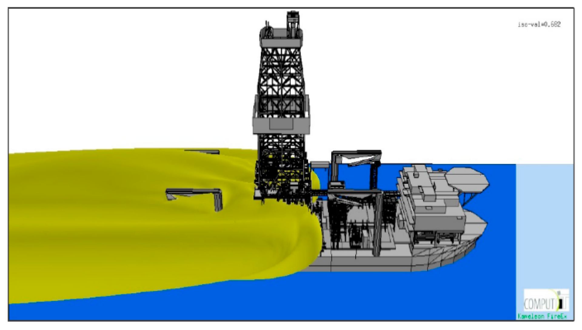
Figure 6 shows the gas cloud with concentration higher than 20% of LFL when gas is released from the center of the telescopic joint where the inner barrel enters the outer barrel. The elevation of the leak point is assumed to be at the middle of the stroke, i.e., approximately 16.3 m below the drill floor level. The release is modelled to be upward as the inner barrel is above the outer barrel of the telescopic joint. The gas is released at full flow rate (150 kg/s), and 5.4 m/s wind blows from the forward direction. The simulation results imply that the released flammable gas is well vented without exposing the topside outside the derrick to the concerned level of concentration (>20% of LFL). According to the simulation result, the aft part of the drillship is engulfed by a gas cloud with concentration higher than 20% LFL.
Explosion simulations were carried out, and snap shots for explosion over and under the drill floor are shown in Figure 7.

4. Blast Pressure Selection from Explosion Analysis Results

4.1. Explosion Model and Pressure Measurement and Grouping

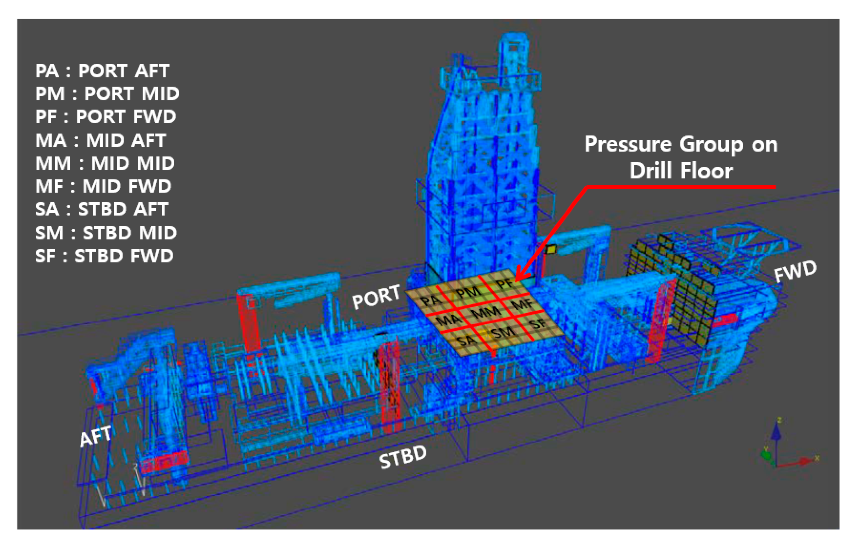
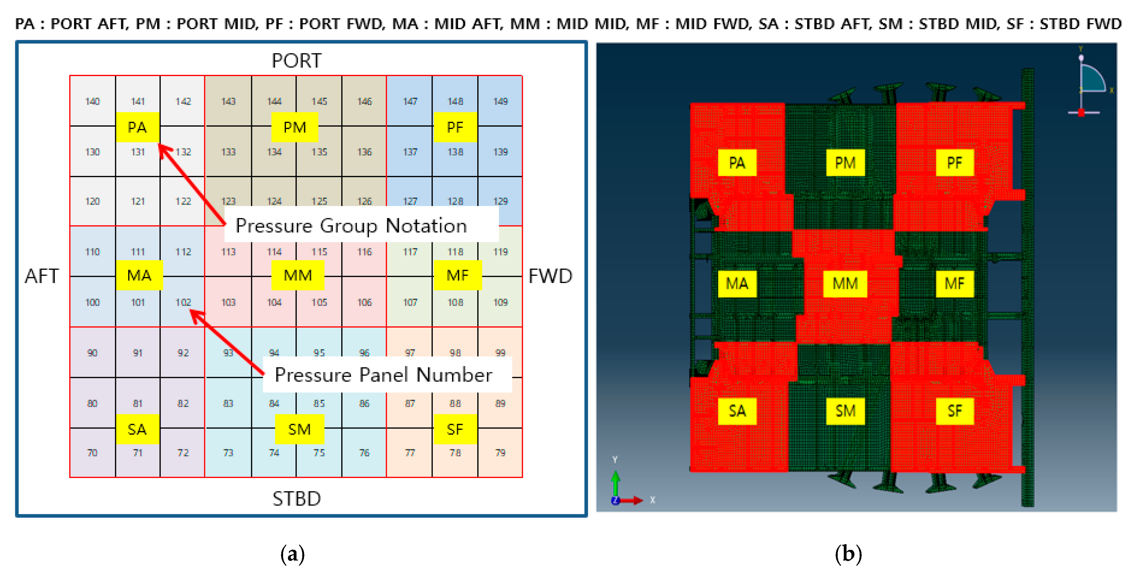
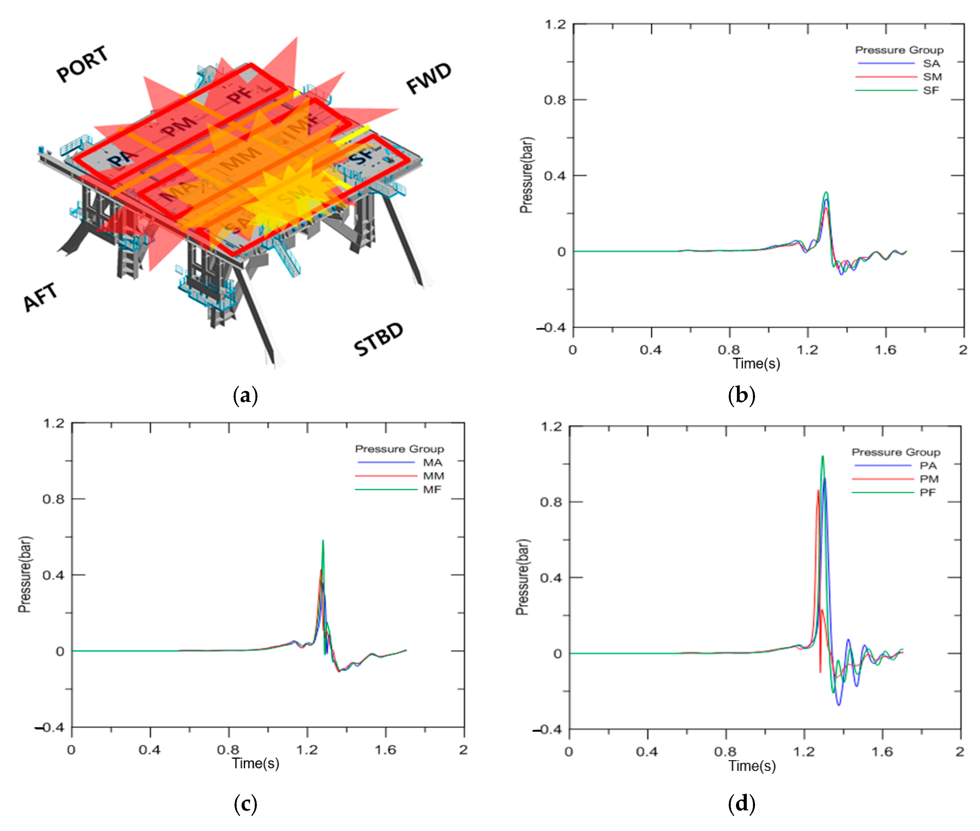
Figure 8 presents the FLACS explosion model based on the geometry that was built to reflect the real features of the drilling unit in detail. The FLACS program imports the geometry model and trims minor parts that would not influence the explosion simulation. The grid square area is the top of the drill floor, and the yellow pressure panels on the drill floor indicate the location where the pressure values are measured. The blast pressure of each panel is the mean value of the panel area. Figure 9a presents the blast pressure group of the drill floor in detail. A pressure group is created for effective application of the blast pressure. Figure 9b presents the application of the finite element model for structural analysis based on the pressure group. The maximum pressure of each pressure group is selected for nonlinear FE analysis.

4.2. Blast Pressure Propagation Features

Figure 10 shows the time history plot of each grouped area of the drill floor. The ignition starts in pressure group SM (starboard-middle) and propagates to the adjacent areas. The pressure amplitude increases in a narrow and confined area. The representative panel has the highest peak blast pressure in each group. Ignition starts at the center of the port surface of the gas cloud, i.e., SM area and propagates to the port side, forward, and backward. The amplitude of pressure increases as the explosion develops. This case is one of the explosion scenarios, and the reason for selecting this case is to consider the highest peak pressure on the drill floor.
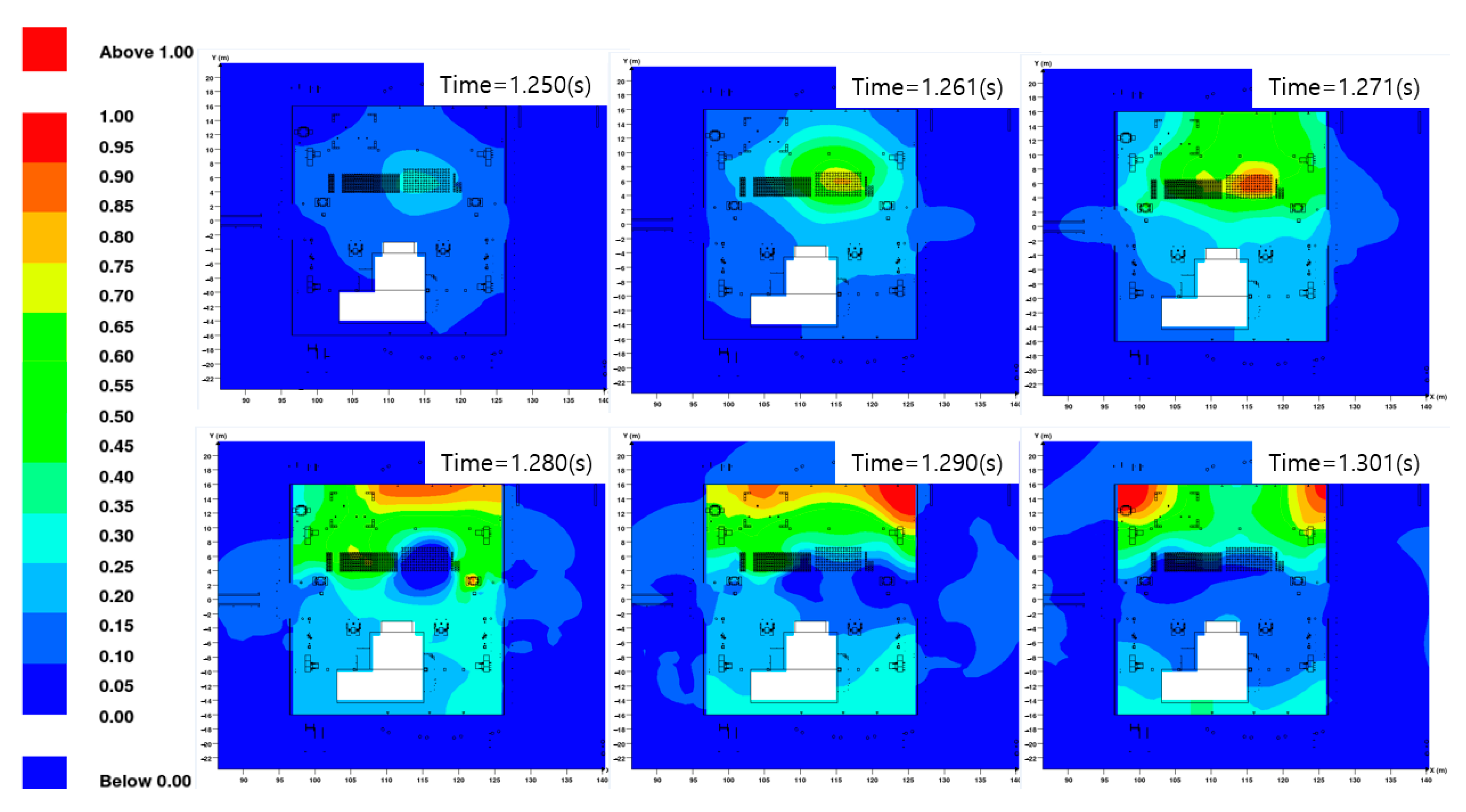
Figure 11 presents the explosion analysis results from the FLACS program according to time about 0.01 s. This shows blast pressure propagation and pressure amplitude according to time. This study suggests reflecting this propagation in Nonlinear FE analysis to pick up realistic behavior of explosions.

4.3. New Methodology for Blast Pressure Application

4.3.1. Idealization of Blast Pressure Profile

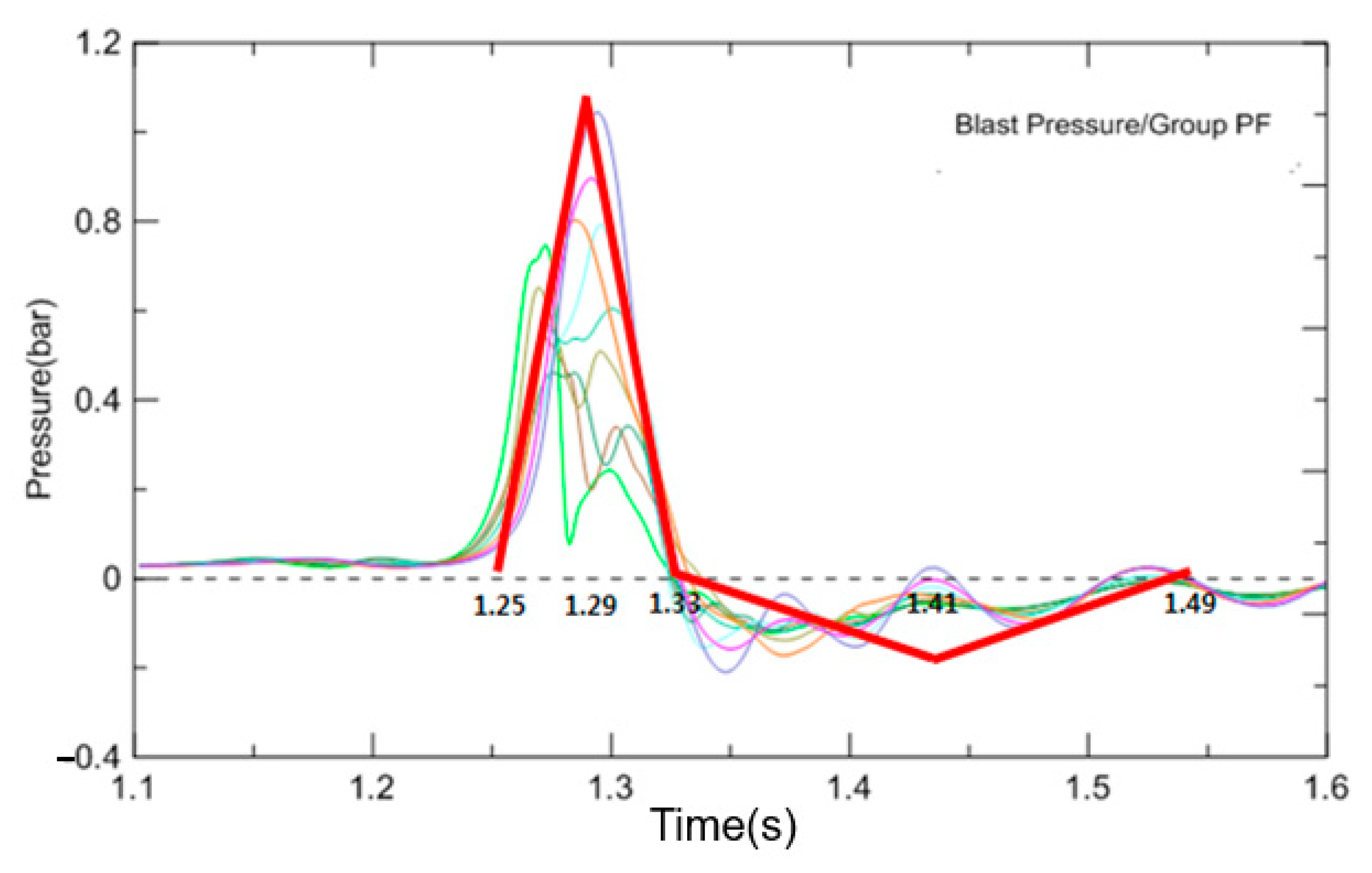
Figure 12 presents the idealization of the representative blast wave of pressure group PF (Port Forward). The maximum blast pressure area is investigated to define the positive and negative phases. It is shown that the positive phase lasts 0.08 s, while the negative phase lasts 0.16 s. The positive peak pressure is observed at 1.29 s and the negative peak pressure is idealized at 1.41 s. The negative pressure duration is two times the positive pressure duration.

4.3.2. Assessment of Blast Pressure Propagation Time

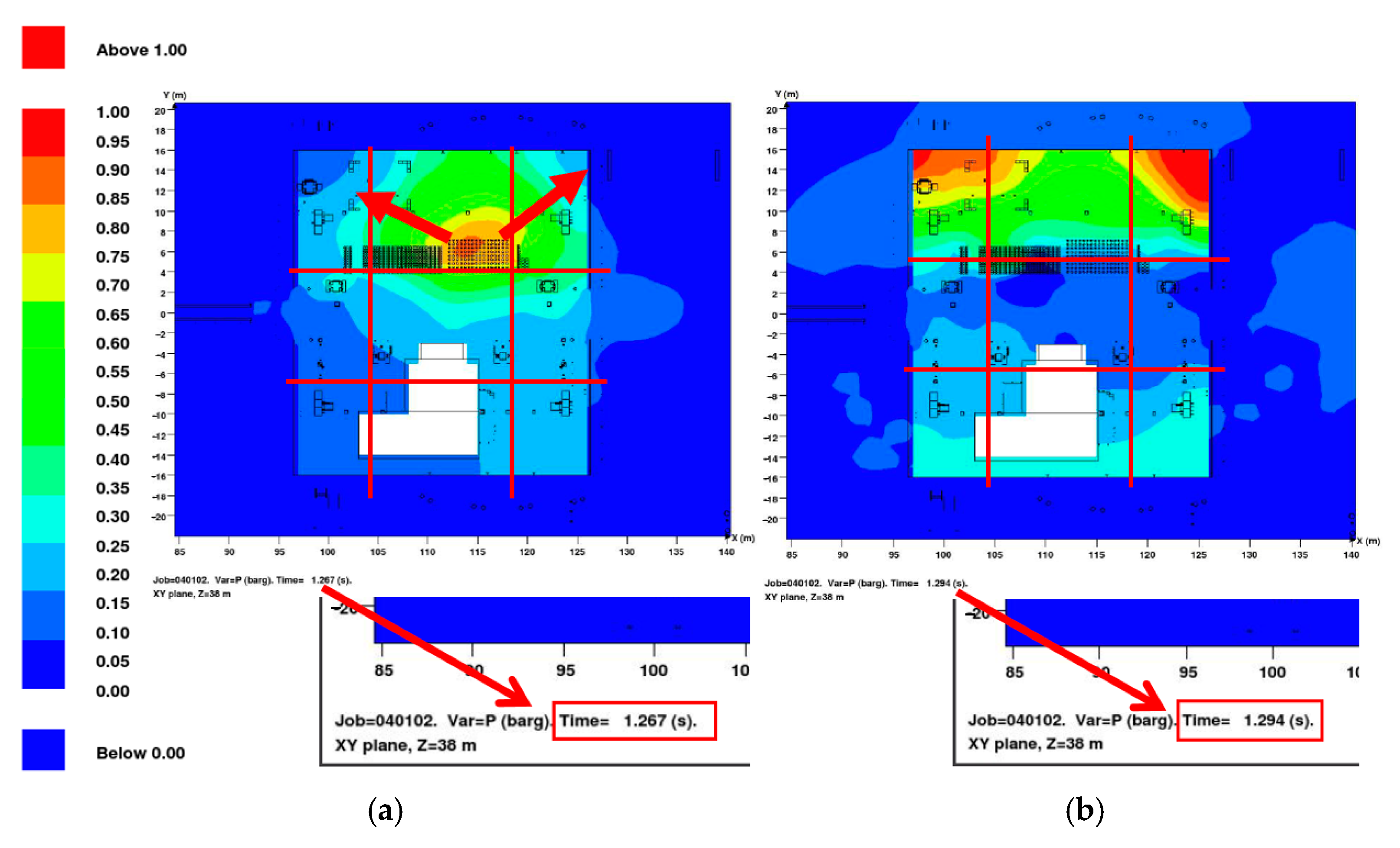
Figure 13 presents the time when the blast pressure moves into another pressure group area. The pressure group areas are divided by the red line. A pressure group consists of nine areas in order to apply pressure effectively. The blast pressure propagation is assumed to take 0.03 s to reach each pressure panel group.

4.3.3. Blast Pressure Application Considering Propagation Features

Figure 14 presents the pressure applied on the pressure groups and the configuration of pressure in the time domain. Figure 14a shows the application of the highest blast pressure of the drill floor on all the areas at the same time. This Overall Peak is widely used in structural analysis due to its simplicity for application; however, it could overestimate the pressure and is considered as a very conservative approach, which results in a heavy blast protection structure. Figure 14b shows the application of the average drill floor blast pressure on all the areas at the same time. This Overall Average uses the same methodology as that of the Overall Peak, except the application pressure. The overall average value of the entire drill floor area is calculated and applied. This method is simple to use; however, it is considered to underestimate the pressure since there exists higher pressure than the average pressure.
Figure 14c shows the application of the peak pressure of each grouped area on each area at the same time. This methodology improved the Overall Peak and Overall Average blast pressure application since these two ways of selecting the pressure could over- or underestimate the blast pressure. This divides the area into groups, selects the peak pressure of the group, and uses it as the blast pressure [14].
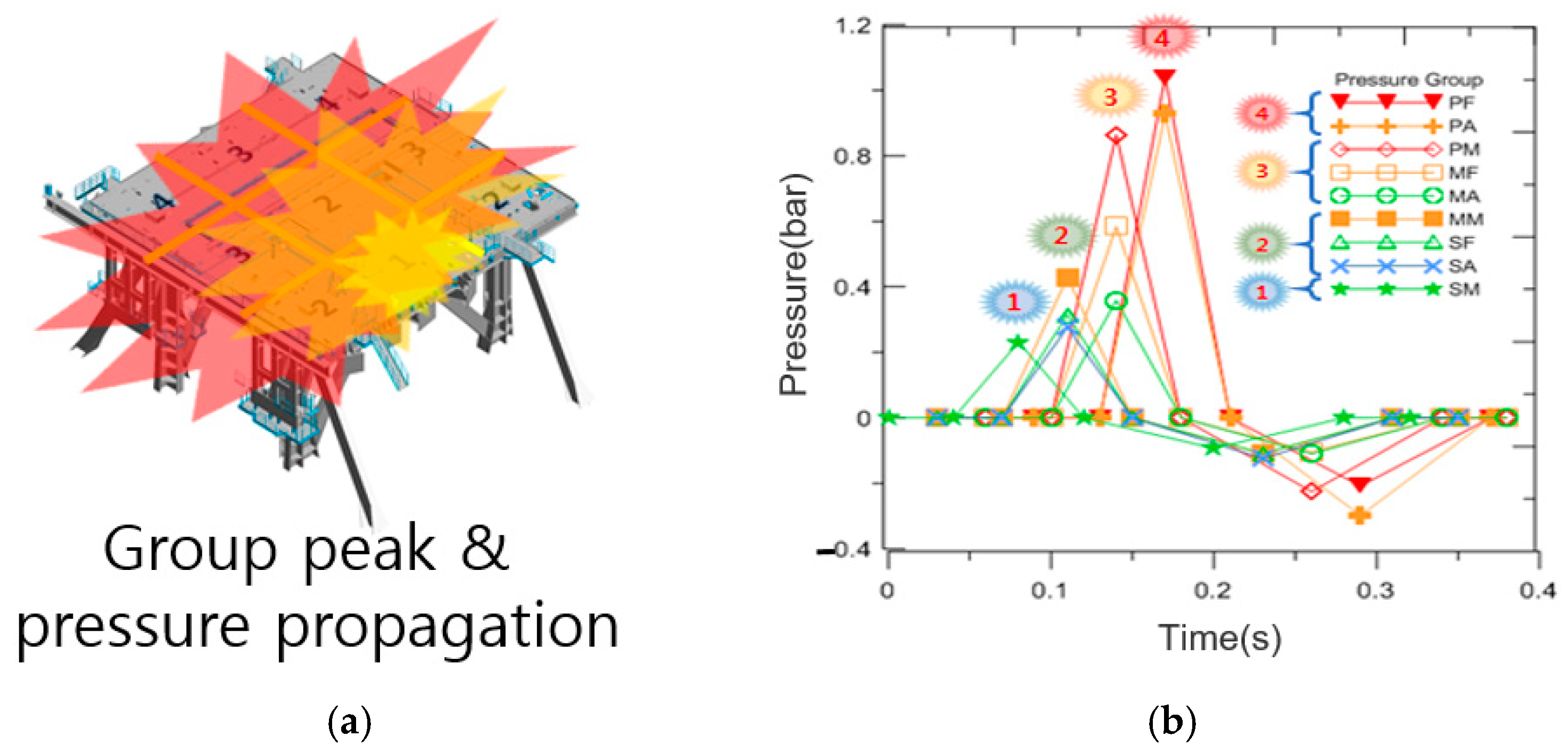
Figure 15 shows the application of peak pressure of each grouped area and includes the blast pressure propagation based on the explosion reviewed in Figure 11 and Figure 13, which represent the nature of explosion. When the ignition occurs in the flammable gas cloud, the explosion propagates through the area. The methodology proposed in this study considers this nature of explosion. Based on the time gap required for propagation through the area, which is obtained from the review of the explosion result, the peak pressure of the group is applied to each group area. Ignition occurs in area No. 1 and the explosion pressure propagates through areas No. 2, No. 3, and No. 4 shown in Figure 15. The result of the explosion shows that the pressure amplitude increased in area No. 4. This can capture the nature of explosion, and the result of each pressure application is investigated in Section 5.

5. Structural Analysis

5.1. Implementation to Finite Element Analysis

5.1.1. Finite Element Model

The numerical analysis was performed using the explicit formulation available in the Abaqus finite element software package, and the equations of motion were solved using the central difference time integration rule [24]. The program is a special-purpose analysis tool that uses explicit dynamic finite element formulation. It is proven to be suitable for modeling brief, transient dynamic events such as blast and impact problems, and has been used in previous research [25,26,27]. The total number of elements and nodes are 84,788 and 81,133, respectively. The mesh size is about 50 × 50 mm2 in order to reflect the details of the drill floor. Element types S4R and S3R were selected for the analysis. S4R stands for 4-node general-purpose shell, reduced integration with hourglass control, finite membrane strains and S3R stands for 3-node triangular general-purpose shell, finite membrane strains. These shell element types in Abaqus use reduced (lower order) integration to form the element stiffness; however, the mass matrix and distributed loadings are still integrated exactly. Reduced integration usually provides more accurate results (provided the elements are not distorted or loaded in in-plane bending) [28].
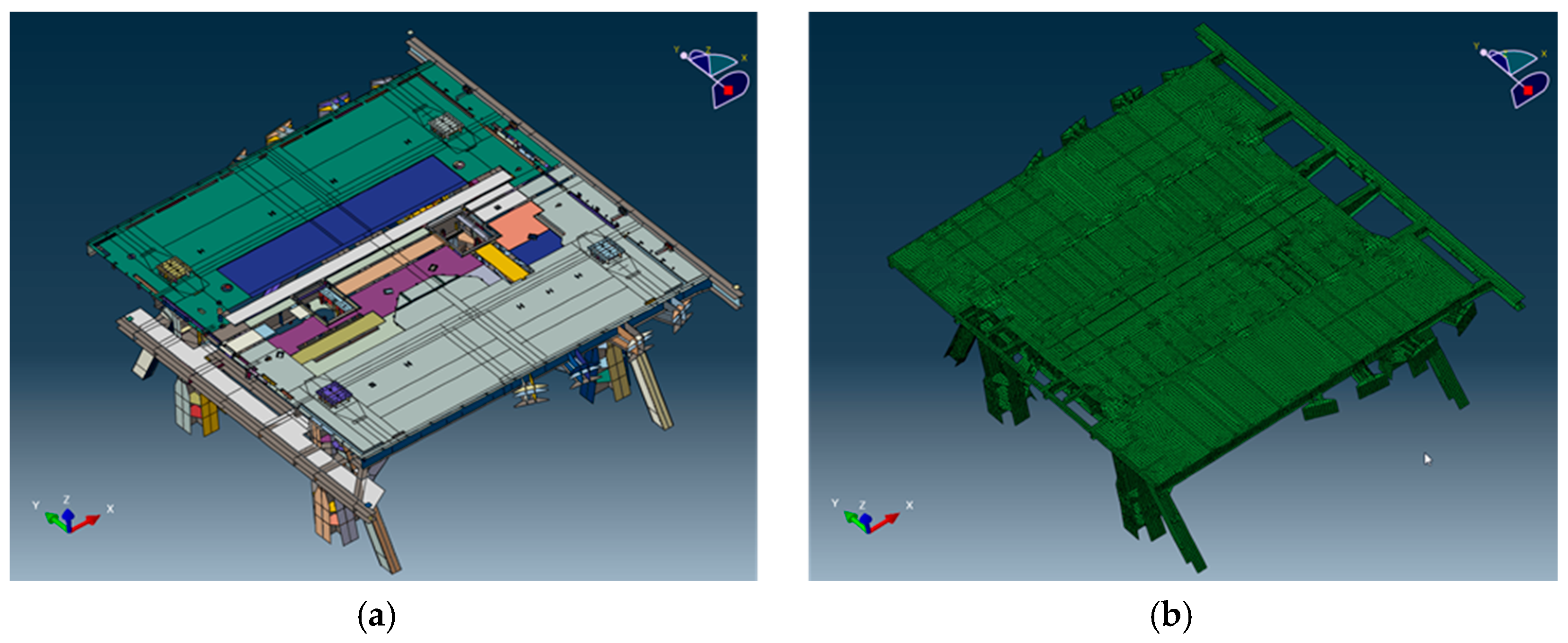
Figure 16 presents the configuration of the geometry and the FE model used in this study. The finite element model for the structural analysis of the drill floor shown in Figure 16b simplifies the geometry model to save analysis time. However, the details of the primary and secondary structures are well represented.

5.1.2. Material Properties and Behavior

The mechanical behavior of the materials that compose the drill floor was defined in accordance with the framework of the finite element analysis. Mild steel, S235, S355, and S460, are typically adopted for the offshore unit and were therefore selected as the structural material of the FE model in this study. The material properties of the selected materials were obtained from DNV Offshore Classification, “Determination of Structural Capacity by Non-linear FE Analysis Methods”, and are summarized in Table 6.
During the FE analysis, the drill floor behaved according to the elastic modulus until the stress reached the yield strength presented in Table 6, and in the plastic region of the stress–strain relation, each material comprising the FE model behaved according to a sequence of the piecewise linear plasticity model, which is commonly adopted for shell elements. From DNV Offshore Classification, an engineering stress–strain curve was obtained and converted to a true stress–strain curve based on the logarithmic relationships that have σ t u r e = σ e n g ( 1 + ε e n g ) and ε t u r e = l n ( 1 + ε e n g ) . The obtained true stress–strain relation was applied to material behavior in the FE analysis.

5.1.3. Strain Rate Effect

The strain rate effect on the material behavior was accounted for by implementing the Cowper–Symonds relation into the material constitutive model in this study. This model is widely used for expressing material behavior under dynamic loading conditions, and in this model, an increase in the stress flow at a high strain rate can be defined by the following Equation (12):
σ D σ S = 1 + ( ϵ ˙ D ) 1 q
where σ D   is the dynamic stress at a particular strain rate, σ S is the static stress, ϵ ˙   is the uniaxial plastic strain rate, and D   and   q are constants for steel.
The scale of increase in the yield strength at a high strain rate can be controlled by the determination constants D and q, which are commonly obtained from the dynamic tensile test results. The test result of S355 and S460 are available in “Elevated temperature and high strain rate properties of offshore steel”. The increase in the yield strength of S235 is obtained from the equation of Cowper–Symonds, and D = 4000 and q = 5 as proposed by DNV-RP-C208.

5.1.4. Structural Design Criteria against Explosion

Owing to the characteristics of onerous accidental events of explosion, the design against explosion allows plastic strain and permanent deformation so that the structure is not too heavy. The general criteria of allowance are shown in Table 6 as critical strain. The design critical strain is less than the fracture strain, and this means that the main structure does not experience fracture with the safety factor. The critical strain is sometimes less than that in Table 6 by 0.05 in order to have sufficient safety factor according to the tendency of the designer or the operator of the facility.

5.1.5. Load Cases According to Explosion Scenario

Table 7 presents the load cases, including the pressure type, area, applied time, and material in order to study the effect of pressure loading type and material. In load case-1, the maximum peak pressure for all pressure group areas is applied at the same time. In load case-2, the averaged peak pressure for all pressure group areas is applied at the same time. In load case-3, the maximum peak pressure for each pressure group area is applied at the same time. In load case-4, the maximum peak pressure for each pressure group area is applied according to the propagation with a time lag.

5.2. Simulation Results and Discussion

5.2.1. Displacement of Frame and Plate of Drill Floor

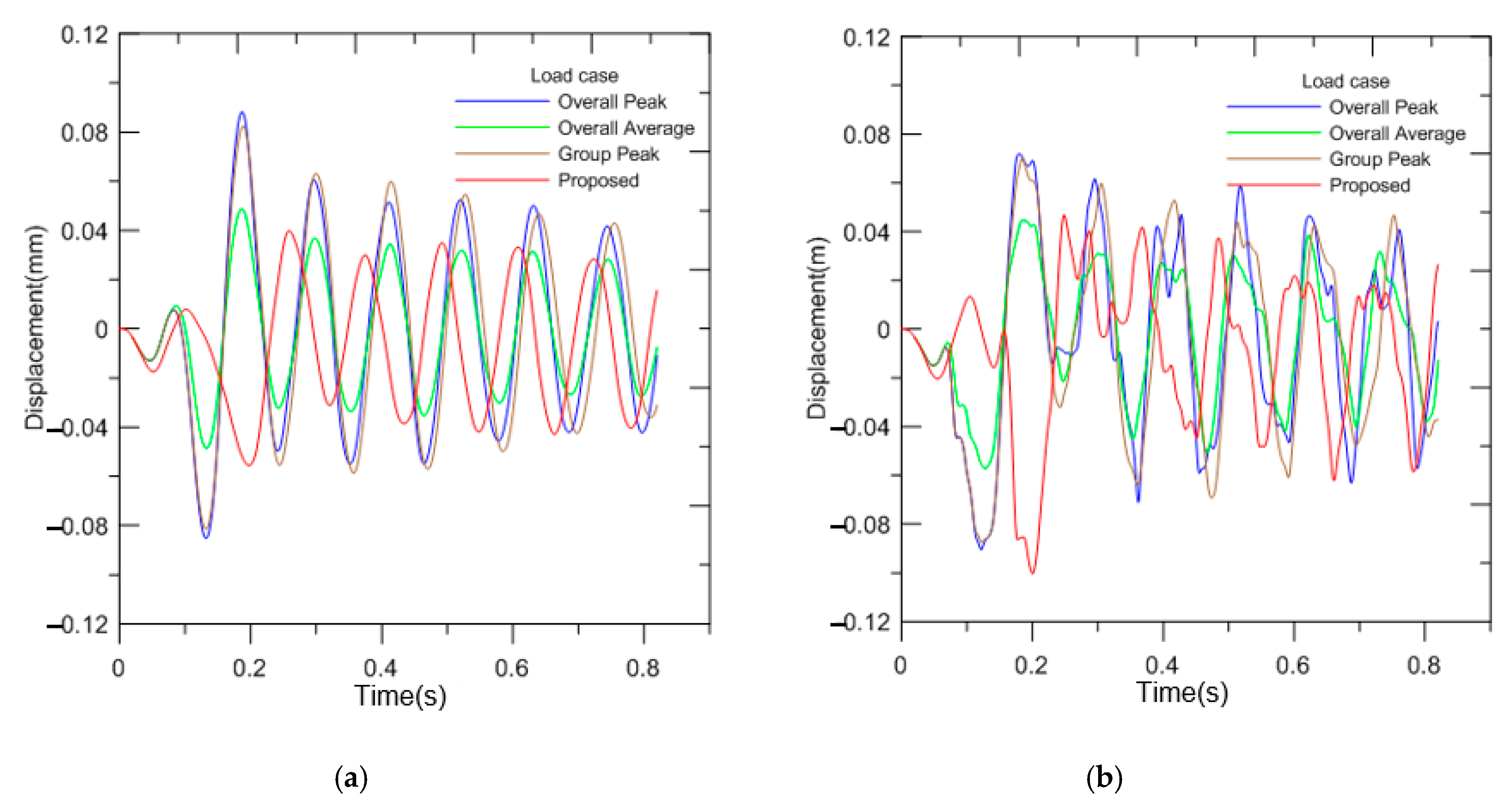
The response of the structure against blast pressure was evaluated through analytical and numerical studies [29,30]. Figure 17 presents the displacement of the frame and plate when blast pressure was applied on the drill floor. The displacement of the frame (Figure 17a) shows clear oscillations unlike the plate in Figure 17b due to higher stiffness. The oscillation of the plate is more complicated than that of a single frame, because a plate has lower stiffness and requires more time for attenuation than a frame.
For displacement of the frame, Overall Average (case-2) has the lowest amplitude of displacement due to the application of the lowest pressure. However, this is the average of the peak pressure of all pressure groups; therefore, using the average value of pressure could result in a less conservative design. Overall Peak (case-1) shows the largest amplitude of displacement among all cases. However, this case applies the highest pressure in each pressure group; therefore, this approach could result in a too conservative design. Group Peak (case-3) and Proposed (case-4) have the peak pressure levels for each pressure group, which are reasonable pressure levels; however, the two cases have different methods of applying pressure according to time. Group Peak (case-3) applies pressure at the same time, whereas Proposed (case-4) involves propagation of blast pressure. Proposed (case-4) seems to be more realistic, since this reflects the actual pressure propagation shown in Figure 15. Proposed (case-4) has less amplitude of displacement than Group Peak (case-3). The difference in displacement according to the material is not expected. The displacements for S355 and S460 were similar to that for S235, as summarized in Table 8.
Due to the complex behavior of displacement, clear characteristics are hardly observed in a plate, compared with the displacement of a frame. Fluctuations last longer than that in a frame due to the lower stiffness. The displacements for S355 and S460 were similar to that for S235, as summarized in Table 9.

5.2.2. Displacement and Area of Plate

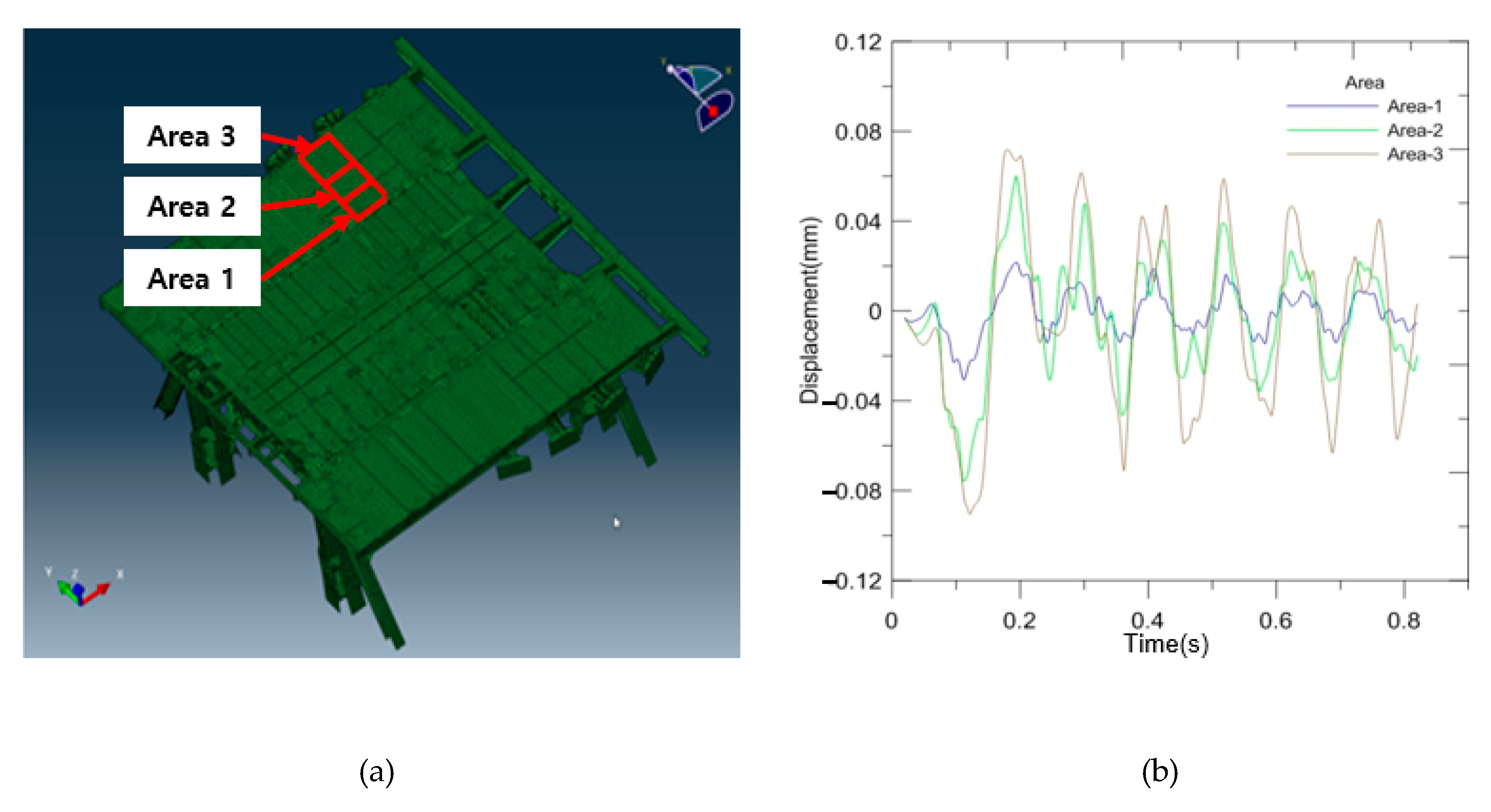
The relationship between plate area and displacement is significant since the displacement of the supports or structures attached to the floor or blast wall due to the blast pressure is influenced by the plate area. Figure 18a presents the location of measurement for displacement, for different area sizes. Explosion for case-1 is selected to investigate the relationship. One side of each area is fixed, and the dimension of the other side is changed.
Figure 18b presents the amplitude of displacement of the plate. The displacement of the middle point of each area is investigated. The size of each area is shown in Table 10. The magnitude of displacement increases according to the size of the plate; however, it is not exactly a proportional relation.
The ratio of displacement increases until the ratio of the two sides of the plate is 1:1, i.e., Area-1 to Area-2 is larger than the ratio of increase in displacement after the ratio of the two sides of the plate is 1:1 (i.e., Area-2 to Area-3). The displacements for S355 and S460 are similar to that for S235, as summarized in Table 10.

5.2.3. Strain of Drill Floor Frame for Applied Pressure

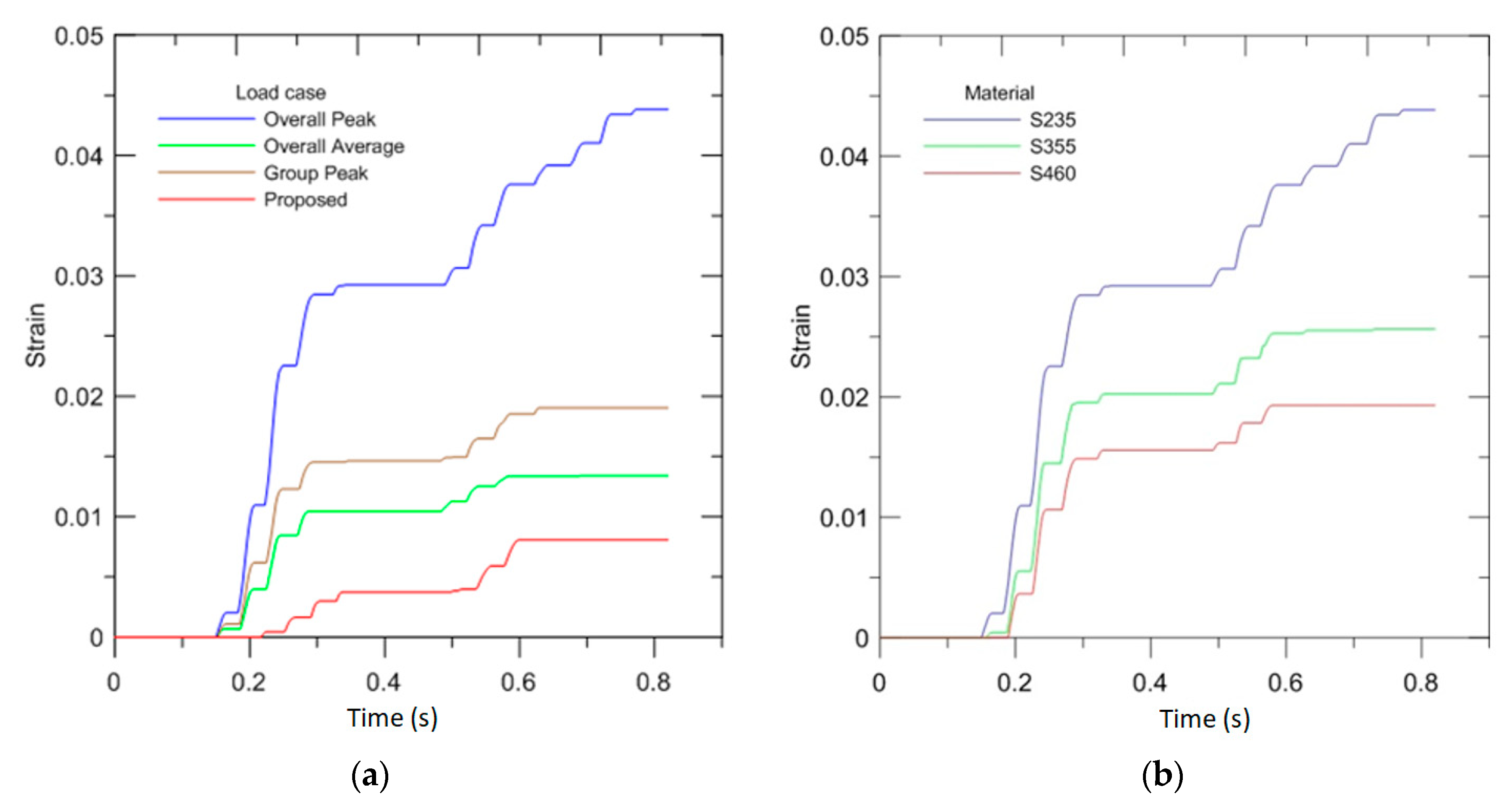
Figure 19a presents the strain profile of frame S235 according to the applied pressure and load cases described in Figure 14 and Figure 15. Overall Peak (case-1) has the largest strain value, followed by Group Peak (case-2) and Overall average (case-3). Proposed (case-4) showed the lowest level of strain. Therefore, the application of propagation of blast pressure can obtain a lower strain result.
It is notable that Proposed (case-4) has the lowest strain level among all cases, although Overall average (case-2) has the average pressure of the panel. This is considered to be due to the new methodology of blast pressure application. Cases-1, 2, and 3 apply blast pressure at the same time; however, case-4 applies the blast pressure in a time interval. This results in the lower level of strain.
Figure 19b presents the strain profile for load case-1 according to the material. S235 has the highest strain level and S460 has the lowest level. The displacements for the same load cases for different materials show almost the same result; however, the material with higher strength shows lower stain. This is due to the higher yield point. Generally, mild steel has been considered to have an advantage when steel experiences ductile behavior, since it has a higher capacity of energy absorbance. However, high strength steel has a low strain level for the same blast pressure. This is meaningful for design, since all blast prevention engineering targets a certain strain level, not a fracture of the structure. High strength materials are preferred for offshore structures due to the payload. Through this study, the selection of high strength materials is justified for strength and blast resistant designs. A plate has no strain at this blast pressure level due to its flexibility compared with a frame structure. A plate is considered to have more capacity for strain than a frame structure. The maximum strain for each load case and material grade is summarized in Table 11.

6. Conclusions

The objective of the present study is to describe the blowout scenario and explosion cases, and then develop an improved application of blast pressure to the drill floor according to the propagation of blast pressure in an offshore drilling unit. The improved pressure application is compared with maximum single, total average, and group pressure application. The inferences from the present study are summarized below.
  • The characteristics of blast pressure propagation after ignition in gas dispersion due to blowout are described. The blast pressure value increases as the explosion propagates the gas volume within the drill floor.
  • This study proposed an improved grouped blast pressure reflecting propagation, which captures the phenomenon of explosion in a more realistic manner. The maximum single method is a very conservative approach and could result in a heavy structure. The total average method is non-conservative and could therefore fail to catch higher pressure than the average. A group method is developed to make up for the above two methods, but it does not fully reflect the nature of explosion. The method proposed in this study captures the nature of the explosion and estimates the blast pressure accurately, therefore contributes to a safer and lighter blast resistant design for offshore facility structures, which are very sensitive to weight due to buoyancy and payload.
  • Different grades of steels generally used in offshore structures are introduced and compared in terms of exposure to blast pressure. As the material for blast resistance, a low tensile material is considered favorable since it has sufficient ductility than high tensile ones. However, this study shows that high tensile material, which is widely used in offshore facilities from the viewpoint of strength, has advantage in strain as well.

Author Contributions

Conceptualization and project administration, J.-M.L.; analysis and writing, T.-K.K.; review and editing, S.-K.K. All authors have read and agreed to the published version of the manuscript.

Funding

This work was supported by the R&D Platform Establishment of Eco-Friendly Hydrogen Propulsion Ship Program (No. 20006644, 20006632) funded by the Ministry of Trade, Industry & Energy (MOTIE, Korea). This work was supported by the National Research Foundation of Korea (NRF) grant funded by the Korea government (MSIT) through GCRC-SOP (No. 2011-0030013).

Conflicts of Interest

The authors declare no conflict of interest.

References

  1. Dan, S.; Lee, C.J.; Park, J.; Shin, D.; Yoon, E.S. Quantitative risk analysis of fire and explosion on the top-side LNG-liquefaction process of LNG-FPSO. Process Saf. Environ. Prot. 2014, 92, 430–441. [Google Scholar] [CrossRef]
  2. Suardin, J.A.; McPhate, A.J.; Sipkema, A.; Childs, M.; Mannan, M.S. Fire and explosion assessment on oil and gas floating production storage offloading (FPSO): An effective screening and comparison tool. Process Saf. Environ. Prot. 2009, 87, 147–160. [Google Scholar] [CrossRef]
  3. Jin, Y.; Jang, B.-S. Probabilistic fire risk analysis and structural safety assessment of FPSO topside module. Ocean Eng. 2015, 104, 725–737. [Google Scholar] [CrossRef]
  4. Bai, Y.; Jin, W.-L. Explosion and Fire Response Analysis for FPSO. In Marine Structural Design; Bai, Y., Ed.; Elsevier: Amsterdam, The Netherlands, 2016; pp. 907–938. [Google Scholar] [CrossRef]
  5. Gupta, S.; Chan, S. A CFD based explosion risk analysis methodology using time varying release rates in dispersion simulations. J. Loss Prev. Process Ind. 2016, 39, 59–67. [Google Scholar] [CrossRef]
  6. Dadashzadeh, M.; Abbassi, R.; Khan, F.; Hawboldt, K. Explosion modeling and analysis of BP Deepwater Horizon accident. Saf. Sci. 2013, 57, 150–160. [Google Scholar] [CrossRef]
  7. Skogdalen, J.E.; Vinnem, J.E. Quantitative risk analysis of oil and gas drilling, using Deepwater Horizon as case study. Reliab. Eng. Syst. Saf. 2012, 100, 58–66. [Google Scholar] [CrossRef]
  8. Xue, L.; Fan, J.; Rausand, M.; Zhang, L. A safety barrier-based accident model for offshore drilling blowouts. J. Loss Prev. Process. Ind. 2013, 26, 164–171. [Google Scholar] [CrossRef]
  9. Sohaimi, A.S.M.; Risby, M.S.; Ishak, S.A.F.M.; Khalis, S.; Norazman, M.N.; Ariffin, I.; Yusof, M.A. Using Computational Fluid Dynamics (CFD) for Blast Wave Propagation under Structure. Procedia Comput. Sci. 2016, 80, 1202–1211. [Google Scholar] [CrossRef] [Green Version]
  10. Hansen, O.R.; Hinze, P.; Engel, D.; Davis, S. Using computational fluid dynamics (CFD) for blast wave predictions. J. Loss Prev. Process Ind. 2010, 23, 885–906. [Google Scholar] [CrossRef]
  11. Paris, L.; Dubois, A. Recent developments to evaluate global explosion loading on complex systems. J. Loss Prev. Process Ind. 2017, 46, 163–176. [Google Scholar] [CrossRef]
  12. Sohn, J.M.; Kim, S.J.; Kim, B.H.; Paik, J.K. Nonlinear structural consequence analysis of FPSO topside blastwalls. Ocean Eng. 2013, 60, 149–162. [Google Scholar] [CrossRef]
  13. Kim, S.J.; Kim, B.J.; Seo, J.K.; Paik, J.K. A New Method for Structural Assessment of Topside Structure Subjected to Hydrocarbon Explosions. Procedia Eng. 2017, 173, 479–486. [Google Scholar] [CrossRef]
  14. Kang, K.-Y.; Choi, K.-H.; Choi, J.W.; Ryu, Y.H.; Lee, J.-M. Explosion induced dynamic responses of blast wall on FPSO topside: Blast loading application methods. Int. J. Nav. Archit. Ocean Eng. 2017, 9, 135–148. [Google Scholar] [CrossRef] [Green Version]
  15. Urgessa, G.S.; Arciszewski, T. Blast response comparison of multiple steel frame connections. Finite Elem. Anal. Des. 2011, 47, 668–675. [Google Scholar] [CrossRef]
  16. Louca, L.A.; Mohamed Ali, R.M. Improving the ductile behaviour of offshore topside structures under extreme loads. Eng. Struct. 2008, 30, 506–521. [Google Scholar] [CrossRef]
  17. Ryu, Y.; Burgan, B.; Choi, J.; Lee, H.S. Structural Safety Analyses for Offshore Platforms under Explosion Loadings. J. Offshore Mech. Arct. Eng. 2019, 141, 041602. [Google Scholar] [CrossRef]
  18. Det Norske Veritas. Accident Statistics for Floating Offshore Units on the UK Continental Shelf 1980–2005; Health and Safety Executive: Derbyshire, UK, 2007.
  19. Li, J.; Ma, G.; Abdel-jawad, M.; Hao, H. Evaluation of Gas Explosion Overpressures at Configurations with Irregularly Arranged Obstacles. J. Perform. Constr. Facil. 2015, 29. [Google Scholar] [CrossRef] [Green Version]
  20. Vannucchi de Camargo, F. Survey on Experimental and Numerical Approaches to Model Underwater Explosion. J. Mar. Sci. Eng. 2019, 7, 15. [Google Scholar] [CrossRef] [Green Version]
  21. Arntzen, B.J. Modelling of Turbulence and Combustion for Simulation of Gas Explosions in Complex Geometries. Ph.D. Thesis, Norwegian University of Science and Technology, NTNU, Trondheim, Norway, 1998. [Google Scholar]
  22. GexconAS. FLACS v10.6 User’s Manual; Gexcon: Bergen, Norway, 2017. [Google Scholar]
  23. Wang, G.; Wang, Y.; Lu, W.; Zhou, W.; Chen, M.; Yan, P. On the determination of the mesh size for numerical simulations of shock wave propagation in near field underwater explosion. Appl. Ocean Res. 2016, 59, 1–9. [Google Scholar] [CrossRef]
  24. Hibbitt, K.S. Abaqus Explicit User’s Manual, version 6.1; Hibbitt, Karlsson & Sorenson: Providence, RI, USA, 2000. [Google Scholar]
  25. Boh, J.W.; Louca, L.A.; Choo, Y.S. Strain rate effects on the response of stainless steel corrugated firewalls subjected to hydrocarbon explosions. J. Constr. Steel Res. 2004, 60, 1–29. [Google Scholar] [CrossRef]
  26. Ling, Q.; He, Y.; He, Y.; Pang, C. Dynamic response of multibody structure subjected to blast loading. Eur. J. Mech. A. Solids 2017, 64, 46–57. [Google Scholar] [CrossRef]
  27. Moghimi, H.; Driver, R.G. Performance assessment of steel plate shear walls under accidental blast loads. J. Constr. Steel Res. 2015, 106, 44–56. [Google Scholar] [CrossRef]
  28. Abaqus Analysis User’s Guide, Abaqus 6.13; Dassault Systèmes: Velizy Villacoublay, France, 2013.
  29. Langdon, G.S.; Schleyer, G.K. Inelastic deformation and failure of profiled stainless steel blast wall panels. Part II: Analytical modelling considerations. Int. J. Impact Eng. 2005, 31, 371–399. [Google Scholar] [CrossRef]
  30. Langdon, G.S.; Schleyer, G.K. Deformation and failure of profiled stainless steel blast wall panels. Part III: Finite element simulations and overall summary. Int. J. Impact Eng. 2006, 32, 988–1012. [Google Scholar] [CrossRef]
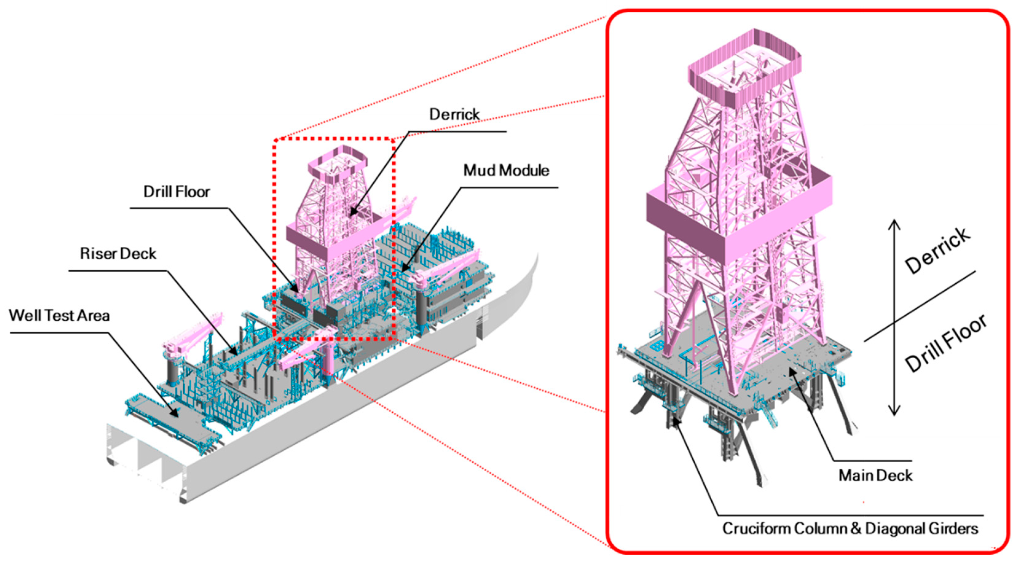
Figure 1. Overview of drillship and drill floor.
Applsci 10 08841 g001
Figure 2. Procedure of drill floor design.
Applsci 10 08841 g002
Figure 3. Gas explosion risk assessment and management (modified from [17]) including proposed methodology for blast pressure application.
Applsci 10 08841 g003
Figure 4. Blowout location (a) on the drill floor and (b) under the drill floor.
Applsci 10 08841 g004
Figure 5. Iso-surface with 20% LFLlower flammable limit (=0.682%) when gas is released on the drill floor with full flowrate and 5.4 m/s wind blows from (a) the forward (b) and aft directions.
Applsci 10 08841 g005
Figure 6. Iso-surface with 20% LFL (=0.682%) when gas is released under the drill floor with full flow rate and 5.4 m/s wind blows from the forward direction.
Applsci 10 08841 g006
Figure 7. (a) Visualization of flame 1.117 s after the gas cloud filling 50% of the derrick volume is ignited at the center of the bottom surface. (b) Visualization of flame 2.106 s after the gas cloud filling 30% of the moon pool volume is ignited at the aft starboard bottom corner.
Applsci 10 08841 g007
Figure 8. Flame Acceleration Simulator (FLACS) model for explosion simulation.
Applsci 10 08841 g008
Figure 9. (a) Pressure group configuration in FLACS explosion model and (b) pressure application on finite element (FE) model.
Applsci 10 08841 g009
Figure 10. (a) Pressure group on the drill floor, (b) time history plot of blast pressure on group SA-SM-SF, (c) time history plot of blast pressure on group MA-MM-MF and (d) time history plot of blast pressure on group PA-PM-PF.
Applsci 10 08841 g010
Figure 11. Explosion analysis result: time plot for blast pressure (maximum pressure 1.04 bar).
Applsci 10 08841 g011
Figure 12. Idealization of blast pressure in PF (Port Forward) for application.
Applsci 10 08841 g012
Figure 13. Propagation of blast pressure (a) at 1.267 s after ignition, (b) at 1.294 s after ignition.
Applsci 10 08841 g013
Figure 14. Blast pressure application and pressure configuration in time domain for (a) overall peak, (b) overall average, and (c) group peak.
Applsci 10 08841 g014
Figure 15. Proposed methodology for blast pressure application: group peak and propagation, (a) blast pressure application and (b) pressure configuration in time domain.
Applsci 10 08841 g015
Figure 16. (a) Geometry model and (b) finite element model of drill floor.
Applsci 10 08841 g016
Figure 17. Displacement of (a) frame and (b) plate (material: S235).
Applsci 10 08841 g017
Figure 18. (a) Location of displacement measurement and (b) measured displacement of plate S235 for each area in case-1.
Applsci 10 08841 g018
Figure 19. Strain profile of (a) frame S235 for each load case and (b) frame for load case-1 according to the material.
Applsci 10 08841 g019
Table 1. Assumed drill floor weight in drilling operation.
DisciplineWeight (ton)
Machinery1500
Structure2000
Steel outfitting150
Outfitting machinery10
Electrical70
Architectural10
HVAC *10
Piping250
Total4000
* HVAC: heating, ventilation, and air conditioning unit.
Table 2. Gas filling ratio and gas volume above the drill floor.
NoFilling
Ratio (%)
Gas Cloud Dimension (m)Volume (m3)
XYZ
150262016.258450
2402620136760
33026209.755070
4202613.349.753382
Table 3. Gas filling ratio and gas volume below the drill floor.
NoFilling
Ratio (%)
Gas Cloud Dimension (m)Volume (m3)
XYZ
1303022.411.27553
2203022.47.55022
31023.817.85.942516
Table 4. Blowout and explosion scenarios above the drill floor.
Ignition PointsFilling RatioCloud Volumes
1. Center of gas cloud (1 point)1. 50%8450 m3
2. Corner of gas cloud (8 points)2. 40%6760 m3
3. Center on surface of gas cloud (6 points)3. 30%5070 m3
4. 20%3382 m3
Table 5. Blowout and explosion scenarios below the drill floor.
Ignition PointsFilling RatioCloud Volumes
1. Center of gas cloud (1 point)1. 30%7553 m3
2. Corner of gas cloud (8 points)2. 20%5022 m3
3. Center on surface of gas cloud (6 points)3. 10%2516 m3
Table 6. Summarization of material properties.
MaterialElastic
Modulus
(GPa)
Poisson’s
Ratio
Density
(kg/m3)
EngineeringTrue
Min.
Yield
Strength
(MPa)
Min.
Ultimate
Strength
(MPa)
Critical
Strain
Min.
Yield
Strength
(MPa)
Min.
Ultimate
Strength
(MPa)
Critical
Strain
S2352050.378502353600.20236.2432.60.1817
S3552050.378503554700.15357.0541.00.1391
S4602050.378504605400.10462.8595.40.0948
Table 7. Load cases for analysis of structure response.
Explosion
Location
Load CasesSteel GradeDeflectionStrain
NoDescription(MPa)
On
Drill Floor
Overall Peak
Case-1
PressurePeak Pressure235Frame
Deck Plate
Frame
Deck Plate
AreaAll Area355
TimeSame Time460
Overall Average
Case-2
PressureAverage Pressure235Frame
Deck Plate
Frame
Deck Plate
AreaAll Area355
TimeSame Time460
Group Peak
Case-3
PressurePeak Pressure235Frame
Deck Plate
Frame
Deck Plate
AreaEach Area355
TimeSame Time460
Proposed
Case-4
PressurePeak Pressure235Frame
Deck Plate
Frame
Deck Plate
AreaEach Area355
TimePropagation460
Under
Drill Floor
Overall Peak
Case-5
PressurePeak Pressure235Frame
Deck Plate
Frame
Deck Plate
AreaAll Area355
TimeSame Time460
Overall Average
Case-6
PressureAverage Pressure235Frame
Deck Plate
Frame
Deck Plate
AreaAll Area355
TimeSame Time460
Group Peak
Case-7
PressurePeak Pressure235Frame
Deck Plate
Frame
Deck Plate
AreaEach Area355
TimeSame Time460
Proposed
Case-8
PressurePeak Pressure235Frame
Deck Plate
Frame
Deck Plate
AreaEach Area355
TimePropagation460
Table 8. Minimum and maximum displacements of frame (m).
Load CaseMaterial
S235S355S460
Overall Peak
Case-1
Min−0.0852−0.0842−0.0842
Max0.08820.08850.0887
Overall Average
Case-2
Min−0.0485−0.0485−0.0485
Max0.04870.04880.0488
Group Peak
Case-3
Min−0.0814−0.0810−0.0809
Max0.08240.08280.0831
Proposed
Case-4
Min−0.0556−0.0554−0.0554
Max0.03980.04030.0404
Table 9. Minimum and maximum displacements of plate (m).
Load CaseMaterial
S235S355S460
Overall Peak
Case-1
Min−0.090−0.089−0.089
Max0.0720.0730.073
Overall Average
Case-2
Min−0.090−0.057−0.057
Max0.0720.0450.045
Group Peak
Case-3
Min−0.088−0.086−0.086
Max0.0700.0690.069
Proposed
Case-4
Min−0.100−0.099−0.099
Max0.0470.0470.047
Table 10. Displacement of plate for areas in case-1.
AreasMaterialDisplacement
Ratio
NameDimensionRatio S235S355S460
Area-12.375 m × 1.305 m1.00Min−0.031−0.031−0.0311.00
3.099Max0.0220.0220.022
Area-22.375 m × 1.995 m1.53Min−0.076−0.076−0.0762.62
4.738Max0.0600.0610.061
Area-32.375 m × 3.155 m2.42Min−0.091−0.089−0.0893.13
7.493Max0.0720.0730.073
Table 11. Maximum strain for each load case and material.
Load CaseMaterial
S235S355S460
Overall Peak
Case-1
4.38%2.57%1.93%
Overall Average
Case-2
1.34%0.36%0.15%
Group Peak
Case-3
1.90%0.79%0.49%
Proposed
Case-4
0.81%0.17%0.00%
Publisher’s Note: MDPI stays neutral with regard to jurisdictional claims in published maps and institutional affiliations.