1. Introduction
The substantial evidence of changing climate [
1,
2] is a trigger for architects and engineers to reconsider the conventional approach to designing the built environment and instead come up with environment-based, climate-conscious design strategies [
3,
4,
5,
6]. Combining performance criteria such as climatic factors with architectural design ideas and blending them into architectural and urban planning might not only lead to efficiently-performing architecture derived from its surroundings, but also might, this way, contribute to mitigating the worst-case scenarios of climate change [
7]. The hither-to last finished assessment report of IPCC (The Intergovernmental Panel on Climate Change) stated that it is the global scientific consensus that humans are most certainly the primary cause of ongoing global warming [
2]. The lockdown of cities during the COVID-19 pandemic proved how human activities are closely linked to the environment. A lockdown of cities for a few months has led to a 12–51% reduction in NO
2 air pollution in the selected European capitals [
8]. It, therefore, can be assumed that targeting the architectural design process on the anticipated future nature- architecture interactions as early as in the phase of concepts and planning can lead to the improved environmental performance of the built environment, which in turn, can favorably influence the ambient microclimate [
9]. Through digital architectural design intertwined with environmental and structural engineering, buildings, as well as the urban environment in the continually changing microclimate, can be created as a reaction to natural forces [
10].
1.1. Designing with the Wind
One of the most evident weather factors markedly shaping natural surroundings is the wind [
11]. In the context of architecture, the wind can “form” the built environment, or, in other words, the wind fluxes interact with the built scenery, which, when unnoticed during the design process, can lead to creating zones with absent wind or, reversely, zones with high-speed wind, accompanied by turbulent flow. Wind analysis of the specific wind conditions of the design site contributes to creating a sustainable, as well as comfortable, built environment [
12].
Until recently, except for the analysis of high-rise buildings and skyscrapers or extreme winds-prone areas [
13], little attention has been paid to the wind evaluation of building designs during their creation. Moreover, although the Computational Fluid Dynamics (CFD) simulations are valuable in architectural design [
14], they are still not a part of the standard architectural practice, especially not in the early design stage [
15]. Decades of CFD software development [
13,
16,
17,
18] enable architects and planners a relatively quick examination of the complex relations of the wind phenomenon in the context of architecture.
Taking the wind microclimate of the design site into consideration in the early conceptual stage of design leads towards creating environment-based buildings, as well as public spaces around them [
3,
12,
19].
1.2. Wind-Architecture Interactions
The magnitude and direction of the wind fluxes are, globally, unevenly distributed (
Figure 1).
Therefore, the designs incorporating the wind can be aimed at different goals, depending on what kind of wind-architecture interaction is beneficial for the specific site: natural ventilation, pollutant dispersion, aerodynamic designs, pedestrian wind comfort, and wind energy harvesting (
Figure 2).
1.2.1. Natural Ventilation
Predicting the effects of natural ventilation between buildings using CFD already from the phase of conceptual ideas would be highly advantageous in hot climates [
21,
22]. The urban design, focusing on the relative position, rotation, and height of buildings, combined with the generative designing, can enhance the natural ventilation efficiency by around 30% [
23]. Predicting the potential of natural ventilation in the urban scale [
22,
23,
24,
25], but also for double-skin building envelopes [
5,
26], leads to sustainable, informed design solutions, which utilize the wind as a renewable resource to improve wind microclimate around buildings, as well as their energy performance.
1.2.2. Pollutant Dispersion
CFD can be incorporated into early-stage designing to predict the effect of the design on dispersing traffic pollution, especially in big cities. In densely-populated areas, a combination of several factors, including the site coverage ratio, frontal area density, buildings’ height, and height diversity, all influence the pollutant dispersion effectivity [
27].
1.2.3. Aerodynamic Designs
Building shape optimization using CFD simulations in colder, or very windy climates, can lead to building forms, which, through their streamlined shape, reduce the wind loads acting on them [
28]. Moreover, when the building structures are subjected to high winds, such as hurricanes, CFD is an essential virtual tool assisting in the mitigation of wind damage to buildings [
29].
1.2.4. Pedestrian Wind Comfort
In a windy street, an open-air tram or bus station without wind protection is uncomfortable for pedestrians. Digital wind analysis can lead to the design of a suitable architectural intervention acting as a wind diffuser, decelerating the wind, thus improving the wind comfort of pedestrians [
30]. Spaces in-between the buildings can also be problematic at the pedestrian level. Again, placing a porous wind barrier in the passage can deflect and decelerate the wind flow and enhance wind comfort [
31]. In the regions with severe sandstorms, a porous wind barrier can reduce the number of sand particles downwind of the designed shelter while also decelerating the wind [
32].
1.2.5. Wind Energy Harvesting
If the design goal is effective wind energy harvesting, the building’s shape, as well as the shape and height of neighboring buildings, are crucial [
33,
34]. Except for wind turbines mounted on building structures, piezoelectric materials applied to facades can also act as wind energy harvesters. Their efficiency, as opposed to the classical generators, is much lower; however, design-wise they undoubtedly are a promising way of combining wind energy harvesting with architecture [
35].
Some of the wind-architecture interactions are presently researched more than others. Uncovering the potential of wind-based aerodynamic buildings, for instance, or options for wind energy harvesting offers a vast space for further research.
1.3. The Goal of the Paper
This paper focuses on examining the reciprocal influences of wind and the built environment at the level of architecture and urbanism. Utilizing a computer-based method, the properties of air, the prevailing wind direction, as well as magnitude can be incorporated as inputs throughout the wind-driven architectural form-finding. In a design case study in Stockholm’s Loudden Docks, the computer-based architectural approach, combining parametric designing with parametric CFD analysis, is demonstrated by the design of three complex shapes, each of them interacting with the wind differently: as a minimum resistance to the wind flow, as an accelerator of the wind, and as a wind-protection for pedestrians. The wind-driven design leads to enhancing the performance of architecture in the wind and enables utilizing the favorable wind effects throughout the lifespan of the designed building.
2. Materials and Methods
Adjusting the architectural design approach to the climate change era means testing the proposed designs, predicting their effects on the local microclimate, and selecting the most fitting (or optimized) design variant [
10]. In this paper, the Research Through Design (RTD) approach is used to create wind-based designs. The process requires an iterative approach to lead to the improved performance of architecture in the wind [
36]. In this paper, however, only one variant for each designed complex architectural shape will be introduced and suggestions for additional wind-based shape optimization will be made.
2.1. Steps of the Proposed Wind-Based Form-Finding Method
The influence of the wind conditions on the built environment can be predicted at the early stages of designing, through CFD simulations, to help understand the expected wind-architecture interactions, and, based on the results, the concept can be adjusted to be optimal for the specific design goal. The steps of the proposed design method (
Figure 3) will, through the case study in Stockholm, gradually demonstrate the process of creating wind-based architecture.
2.1.1. Wind Data
The first step is obtaining the digital wind data, as an *epw (EnergyPlus weather) file, a collection of archived meteorological stations’ recordings through the past 25 years [
37]. The graphical wind-rose, a visual interpretation of the annual and monthly wind speeds, directions, as well as frequency, is shown in
Figure 4. It is observed that the westerly winds are prevailing, while the wind gusts are mainly southerly and northerly. When assessing a design for wind comfort, two threshold wind speeds are observed, following the Dutch standard NEN 8100 [
38]: 5 m/s and 15 m/s. If the threshold wind speed of 5 m/s is exceeded >10% of the year (in Stockholm, it is 18.77%), this results in poor conditions for strolling and sitting activities. Moreover, accompanied by the colder air temperature, which is around 5 °C to 18 °C in the area of Stockholm, the exterior wind comfort further deteriorates. If the wind speed of 15 m/s is exceeded >0.05% of the year (in Stockholm, it is 0.25%), this indicates a limited risk of wind danger for pedestrians.
2.1.2. Parametric Designing Coupled with CFD Simulations
Parametric designing simplifies the process of working with multiple design alternatives, therefore leading to selecting the most suitable variant within the design context [
39]. The parametric architectural software Rhinoceros and its algorithmic plug-in, Grasshopper, enable the exchange of information between the design and simulation software, which, applied to the nature-driven architectural form-finding, leads to the creation of several environment-responsive design choices [
40].
Concerning the parametric definition in the wind-based design process, the best performance of the design in the wind will be achieved when parametric variables are set correctly, according to the design intentions (
Table 1).
The wind-based shape optimization, or, in other words, the exploration of multiple design directions in the conceptual design stage, based on their performance in the wind, needs to be as effective as possible. Through examining various CFD software, it was observed that the most efficient for the early design stage, in terms of cost, time, and accuracy, is the CFD analysis within a 3D modeling environment. Swift for Grasshopper, utilizing OpenFOAM for the CFD calculations, enables parametrically setting the virtual wind tunnel (VWT), as well as boundary conditions in the same Grasshopper file.
The SimpleFoam (Semi-Implicit Method for Pressure-Linked Equations) iterative algorithm, RAS (Reynolds-Averaged Simulation), and the Standard k-ε turbulent model are used in Swift for computing Navier-Stokes equations [
41]. As the algorithm is iterative, we have to determine when the calculations stop by setting the number of iterations, or convergence criteria, or both. Convergence criteria define when the initial residuals of pressure
p, velocity components
vx,y,z, as well as the turbulent kinetic energy
k, and turbulent kinetic energy dissipation
ε stop changing or are small enough. Swift, running on the OpenFOAM platform, uses kinematic pressure within incompressible flow solvers:
where
pk is the kinematic pressure [m
2/s
2],
pa is the static pressure [Pa], and
ρ is the density of the flow [kg/m
3]. The kinematic pressure will subsequently be converted to Pa, multiplying it by 1.25 kg/m
3. This value is used in Eurocode 1 to represent the density of air [
42].
3. Brownfield in Loudden Docks, Stockholm Case Study
Closing the Loudden Docks in 2011 with the perspective of the revitalization of the district within the Stockholm Royal Project [
43] changed the strategic port into a brownfield, consisting of more than 100 empty, cylindrically-shaped, 10–35 m tall reinforced-concrete silos (
Figure 5).
The impulse for choosing this site for the case study was a 2017 architectural competition, seeking alternative, creative architectural ideas for Loudden Docks. Through the applied wind-based method, it will be demonstrated that minimal architectural interventions can transform the turbulent wind flow caused by the clustered urban distribution of silos while keeping the unique character of the site.
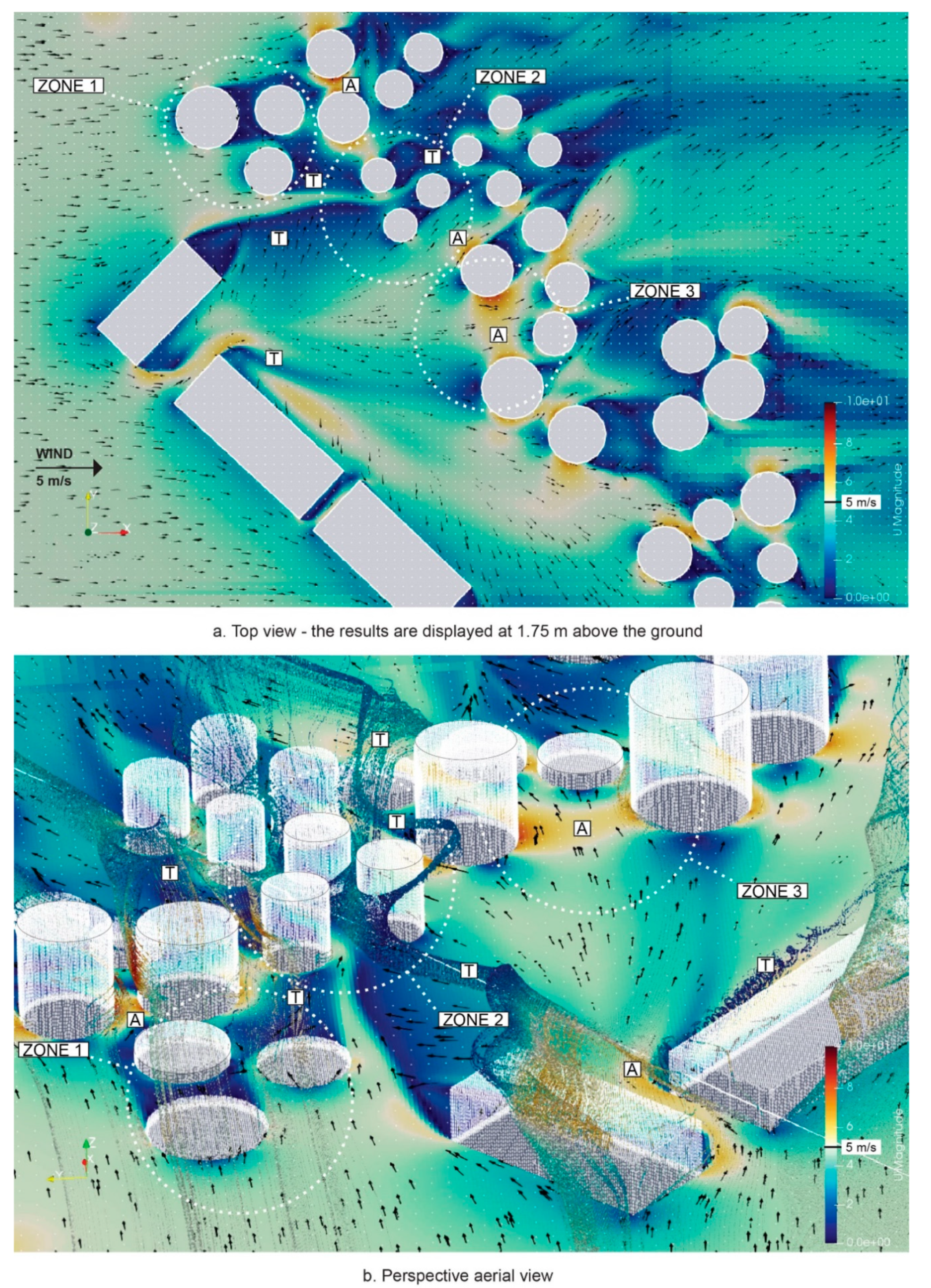
3.1. The Present Wind Situation on the Site
The case study proposes the demolition of the smallest silos and a reduction of the height of some of them. The wind conditions are investigated for two wind speeds, 5 m/s and 9 m/s, representing the westerly winds and southerly wind gusts, respectively. Within Loudden Docks, three zones are examined further. In the CFD simulation in Swift, the cell size of the virtual wind tunnel is 4 m, the terrain roughness is set to 1, and the meshing is refined around the geometry of interest. The relaxation factors for the calculations are the following: p = 0.3, vx,y,z = 0.7, k|ε = 0.7. The convergence criteria are set to determine that the calculations stop once the initial residuals are the following: the pressure p < 0.05, the velocity components vx,y,z < 0.01, the kinetic energy k, and the dissipation rate of the kinetic energy ε < 0.01.
The westerly winds simulation converged in 495 iterations, and the southerly winds simulation in 388 iterations. In
Figure 6 and
Figure 7, the wind analysis results, post-processed in Paraview, are displayed at a horizontal plane, 1.75 m above the ground. Accelerated wind flow (A), as well as turbulent flow (T), are highlighted. The accelerated wind flow, as well as turbulent wakes, are not desirable in zones 1 and 3; however, with suitable architectural interventions, the wind comfort can be provided (employing the windbreak), or the turbulence can be reduced (with a fluid architecture). Venturi effect (acceleration of the flow, passing through a restriction) is favored in zone 2 and utilized for harvesting the wind energy.
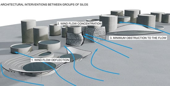
3.2. The Proposal
The urbanism concept is to convert the brownfield, characterized by unique morphology, to a “wind park” by proposing three different architectural interventions in three zones. A deflection of the wind flow is proposed in zone 1, where wind protection of swimming pools (or ice rinks in winter) is designed around silos, which are reduced in height. An acceleration/concentration of the wind is proposed in zone 2 to harvest wind energy employing piezoelectric cantilevered elements placed on the building skin. An aerodynamically-shaped cultural auditorium is proposed in zone 3. These complex building forms are, in this research, called “FlowBrane” as tensile membranes controlling the wind flow (
Figure 8).
3.3. Parametric Wind-Based Design
3.3.1. Zone 1: Architecture Deflecting the Wind Flow
A lightweight FlowBrane No. 1 serving as wind protection from the two main wind directions deflects the flow from the swimming area. This porous tensile membrane, vertically inclined towards the flow, is translucent and, at the same time, can protect the baths from the cold winds. Compared to solid windbreaks, permeable barriers with around 30% porosity tend to be more effective in reducing the wind speed and turbulent wind energy. Also, the wind-protected space on the leeward side is bigger [
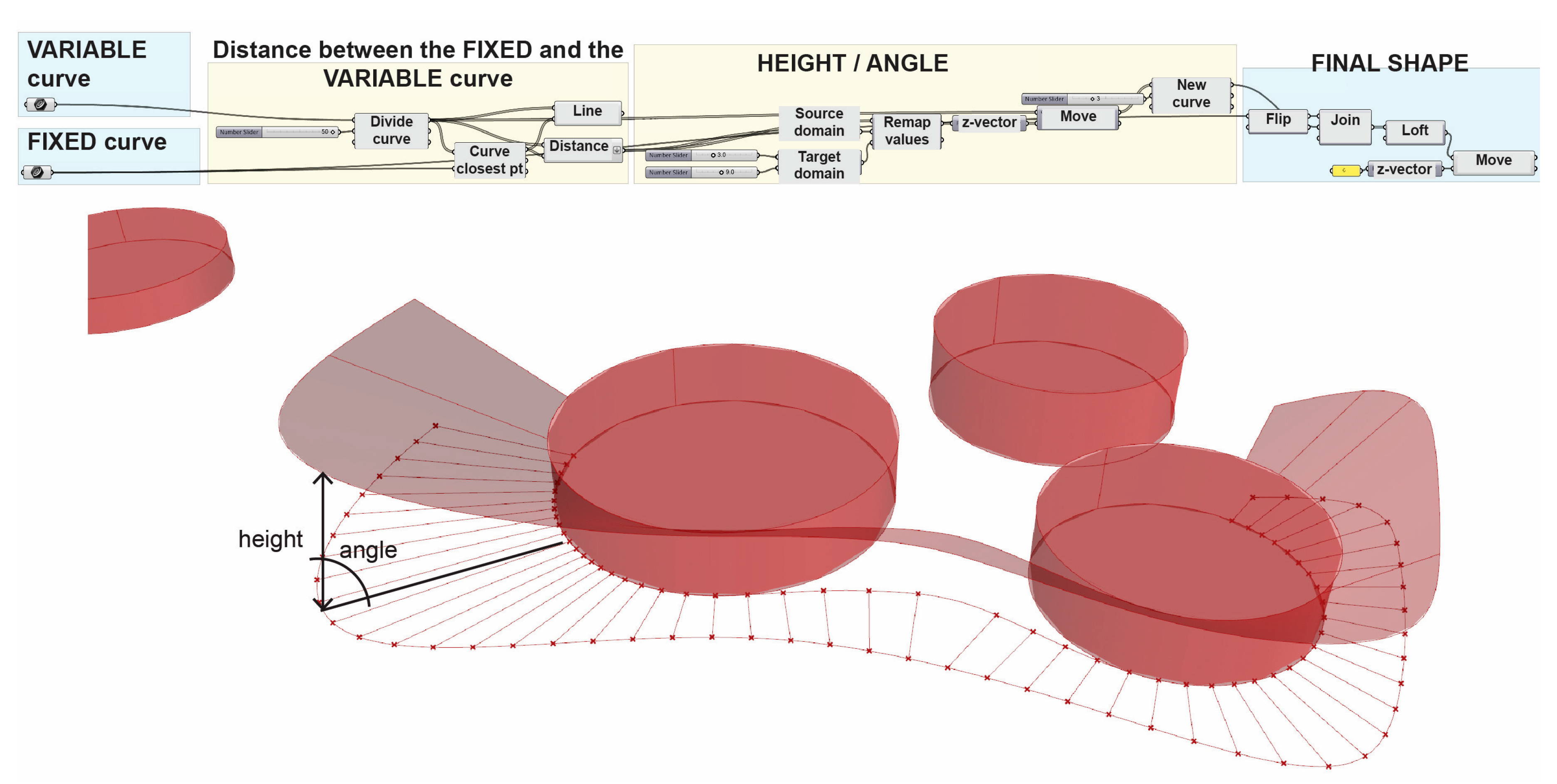
44]. The membrane, however, will be analyzed as a solid geometry. The FlowBrane No. 1 is a wavy shape, protecting the baths in different wind approaching angles.
Modeled parametrically, height
h, and the lift angle
α (an inclination towards the wind flow) of the wind-shielding membrane can be altered, with the height constrained between 3 and 9 m. Together with another parametric variable, a contour curve, the final shape is defined (
Figure 9).
3.3.2. Zone 2: Architecture Accelerating the Wind Flow
FlowBrane No. 2 is designed as a set of three membranes, twining around three silos. The configuration, as well as the shapes of three membranes, enable the squeezing of the wind between them, enhancing the already existing Venturi effect between the silos. Thus, the wind energy can be, incorporating the cantilevered, 1.2 m long piezoelectric straws, covering the envelope of FlowBrane No. 2, efficiently harvested, especially when the resonant frequency of the piezoelectric straws matches the wind vortex shedding frequency [
45] (
Figure 10).
In the parametric definition, the contour curves of FlowBrane No. 2 control the global shapes and hence the main features that impact the acceleration of the flow: size and form of the openings (restrictions through which the flow passes) between the shapes (
Figure 10).
3.3.3. Zone 3: Architecture as a Minimal Obstruction to the Wind Flow
The goal of creating aerodynamically-shaped buildings is to ensure a minimum resistance of the designed architecture to the wind flow, hence reducing turbulence. Ultimately, this affects the magnitude of wind pressure acting on building envelopes [
46]. FlowBrane No. 3, designed in the parametric definition through the profile curves which control the length as well as the height of the auditorium, is aerodynamic in both westerly and southerly winds (
Figure 11).
3.4. Parametric CFD Analysis
With the parametric approach employed in the wind-based design process, any number of shape options can be analyzed using Swift CFD analysis. Within the scope of this paper, one shape variant for each FlowBrane is picked and tested in the urban context (
Figure 12 and
Figure 13).
The CFD tests of the three “FlowBrane” shapes are performed with the same VWT settings as the previous CFD analyzes (see
Section 3.1). The ultimate impact of all designed shapes on the wind flow is juxtaposed to the situation before architectural interventions.
3.4.1. FlowBrane No. 1
In the 5 m/s westerly winds, the designed lightweight and transparent FlowBrane No. 1 deflects the wind and provides wind comfort for the swimming activities. The wind speed behind the barrier is reduced to around 0–2 m/s, with a weak wind swirl of approximately 3 m/s above the water surface of the bigger swimming pool. In the 9 m/s southerly wind gusts, FlowBrane No. 1 can effectively shield the baths from strong wind. Despite wind swirls of around 6 m/s appearing above the water surface of the smaller pool, the wind above the swimming pools is calm. Between the swimming pools, although vertically deflected, the flow slightly accelerates.
The membrane can protect the swimming activities for both the prevailing westerly winds, as well as the southerly gusts. In the process of shape optimization of FlowBrane No. 1, an adjustment of the inclination of the membrane towards the wind flow could enhance the wind protection of the space between pools, especially in the southerly winds.
3.4.2. FlowBrane No. 2
The simulation of the 5 m/s westerly winds reveals that the flow can be squeezed to reach velocities between 6 to 9 m/s. A higher wind acceleration is achieved by employing designed shapes as opposed to the original state. Through the simulations of the 9 m/s southerly wind gusts, we can predict that the three membranes can accelerate the passing wind to speeds up to 18 m/s. The fluid shape of FlowBrane No. 2 not only accelerates the flow to harvest the energy but has aerodynamic properties as well, which further reduce the turbulence.
The shape of the three membranes can be further optimized, aiming at the reduction of the turbulence on the leeward side, as the turbulent flow decreases the efficiency of the wind energy harvesting. If the three membranes are even more streamlined, they will induce less resistance to the wind flow. Hence, by employing piezoelectric straws, wind energy can be harvested more efficiently.
3.4.3. FlowBrane No. 3
The third FlowBrane shows a design of aerodynamic architecture, which only minimally interferes with the wind flow. The CFD analysis of the site without the new architectural interventions showed an accelerated flow between the two silos, selected for the placement of FlowBrane No. 3 in the westerly winds. Moreover, in the southerly gusts, the zone is in a turbulent wake of one of the silos (
Figure 6 and
Figure 7).
With the new intervention, the wind flow approaching from the west is, by the designed aerodynamic form, deflected in the horizontal as well as vertical direction. That results in an acceleration of the flow on the top of the shape and the lateral sides (
Figure 12). The maximum wind suction on the designed membrane in the 5 m/s westerly winds is −20 m
2/s
2 (−25 Pa), while the maximum wind pressure equals +17 m
2/s
2 (+21.25 Pa). The drag coefficient
cd depends on the reference area
A of the object, drag force
Fd, air density
ρ, and the mean wind velocity
vm. In westerly winds, the calculated value of
cd in Paraview equals 0.396, meaning the designed shape is very aerodynamic. FlowBrane No. 3 is even more streamlined in the southerly gusts with the drag coefficient
cd 0.049. The maximum value of the wind suction on the membrane surface in the 9 m/s southerly gusts is −40 m
2/s
2 (−50 Pa), the maximum wind pressure is +43 m
2/s
2 (+53.75 Pa).
The aerodynamic form of FlowBrane No. 3 influences the reduction of surface wind pressure, positive or negative, which can lead to lighter-structured envelopes.
The further shape optimization could focus on making the west façade of the auditorium even more fluid to eliminate the wind acceleration on the top of the designed shape.
4. Discussion
In the unique morphological and wind conditions of the Loudden Docks’ case study site, three FlowBrane shapes, all designed as lightweight tensile membranes, interact with the wind to adjust the microclimate of the place. Three different design directions are pursued: (i) deflecting the wind to protect swimming baths, (ii) accelerating the flow to improve the efficiency of wind energy harvesting, and (iii) creating a fluid architectural form, aiming at reducing the robustness of building structures.
The dynamic ambient conditions are a significant factor influencing architectural design. With the progress in digital designing, the effects of the environment can be simulated and predicted already in the conceptual design phase, which enables the creation of environment-fitting sustainable architectural solutions through employing the iterative process of RTD.
The proposed wind-based design approach intertwines parametric modeling with fast parametric CFD simulations. The wind-based shape-optimization design process consists of wind-driven form-finding in Grasshopper, followed by wind simulations in Swift, and then looping back to the parametric adjustments of the geometry until the desired performance of the design in the wind is achieved.
The three tensile-membrane architectural interventions transform the environment, characterized by Venturi effect, wind turbulence, and an unpleasant environment for pedestrians to a habitable “wind park”. The wind is controlled in a specific way, employing each FlowBrane. Only one shape for every FlowBrane was analyzed utilizing CFD with suggestions on how to continue the wind-based shape optimization. The wavy FlowBrane No. 1 can deflect not only the prevailing westerly but also the strong southerly winds. However, the lift angle and the height of the middle part of the tensile membrane could be adjusted to protect the pools even better. The set of three membranes of FlowBrane No. 2 are wrapping the group of three silos and enhancing the Venturi effect between them. The Venturi effect is in this case desirable because, through the membranes equipped with piezoelectric straws, it is used for wind energy harvesting. The unfavorable wind effect was transformed into a desirable phenomenon by employing architecture. In both examined wind directions, FlowBrane No. 2 can accelerate the wind squeezed between membranes to twofold speed. The third membrane, designed to function as an auditorium, was aerodynamically-shaped. As the envelope spans over tens of meters, its lightness is essential. Fluid architecture resists the wind flow much less, resulting in reduced pressure on the envelope and, consequently, lighter structures.
5. Conclusions
5.1. Benefits of the Proposed Method
The presented digital wind-based design method enables architects to estimate the influence of their designs on the wind during the conceptual phase.
With the utilization of open-source CFD tools within the process, the wind-based approach can become a part of the day-to-day design routine.
Carefully-designed architecture can, through the shape, proportions, and urban configuration, utilize the advantages of wind flow.
5.2. Limits of the Proposed Method
The parametric CFD solver does not account for the material properties. It would be interesting to examine the behavior of materially-different building envelopes in the wind, especially when designing wind-adaptive shape-shifting buildings.
At the moment, the method focuses only on one weather parameter that influences the building envelope. Further research could aim at combining several parameters, such as solar radiation or thermal comfort around buildings, leading to multi-criteria shape optimization of the designs.
Author Contributions
Conceptualization, L.K., D.K. and S.K.; methodology, L.K., D.K. and S.K.; software, L.K.; validation, L.K., D.K. and S.K.; formal analysis, L.K.; investigation, L.K.; resources, L.K.; data curation, L.K.; writing—original draft preparation, L.K.; writing—review and editing, L.K.; visualization, L.K.; supervision, D.K. and S.K.; project administration, D.K. and S.K.; funding acquisition, D.K. and S.K. All authors have read and agreed to the published version of the manuscript.
Funding
This research was funded by VEGA (The Scientific Grant Agency of the Slovak Republic), grant numbers VEGA 1/0674/18 and VEGA 1/0129/20.
Acknowledgments
The authors would like to thank Eva Kormaníková, Henri Achten, and Angelos Chronis for their creative support.
Conflicts of Interest
The authors declare no conflict of interest. The funders had no role in the design of the study; in the collection, analyses, or interpretation of data; in the writing of the manuscript, or in the decision to publish the results.
References
- Callery, S.; Bailey, D. Global Climate Change. Available online: https://climate.nasa.gov/ (accessed on 22 April 2020).
- Pachauri, R.K.; Meyer, L.A. Climate Change 2014. Synthesis Report. Contribution of Working Groups I, II and III to the Fifth Assessment Report of the IPCC; IPCC: Geneva, Switzerland, 2014. [Google Scholar]
- Kuismanen, K. Climate-Conscious Architecture: Design and Wind Testing Method for Climates in Change; University of Oulu: Oulu, Finland, 2008. [Google Scholar]
- Sung, D.K. Skin Deep: Breathing Life into the Layer between Man and Nature; University of Southern California: Los Angeles, CA, USA, 2008; Volume 3. [Google Scholar]
- Doumpioti, C.; Greenberg, E.L.; Karatzas, K. Embedded intelligence: Material responsiveness in façade systems. In Proceedings of the 30th Annual Conference of the Association for Computer Aided Design in Architecture ACADIA 2010, New York, NY, USA, 21–24 October 2010; pp. 258–262. [Google Scholar]
- Persiani, S.; Battisti, A.; Persiani, S.G.L.; Wolf, T. Autoreactive architectural facades-discussing unpowered kinetic building skins and the method of evolutionary optimization. In Proceedings of the 11th Conference on Adaptive Building Skins, Bern, Switzerland, 10–11 October 2016. [Google Scholar]
- Kerestes, J.F. Design Out of Necessity: Architectural Approach to Extreme Climatic Conditions. In Proceedings of the SIGRADI 2014: Design in Freedom; Blucher Design Proceedings, Montevideo, Uruguay, 12–14 November 2014; Volume 1, pp. 130–133. [Google Scholar]
- Lobelia Earth. KNMI COVID-19 Lockdown: Air Pollution in Cities. Available online: https://www.lobelia.earth/covid-19 (accessed on 12 August 2020).
- Edwards, B. Rough Guide to Sustainability; RIBA Publishing: London, UK, 2010. [Google Scholar]
- Lenzholzer, S.; Brown, R.D. Post-positivist microclimatic urban design research: A review. Landsc. Urban Plan. 2016, 153, 111–121. [Google Scholar] [CrossRef]
- Goudie, A.S. Mega-Yardangs: A Global Analysis. Geogr. Compass 2017, 1, 65–81. [Google Scholar] [CrossRef]
- Jin, H.; Liu, Z.; Jin, Y.; Kang, J.; Liu, J. The Effects of Residential Area Building Layout on Outdoor Wind Environment at the Pedestrian Level in Severe Cold Regions of China. Sustainability 2017, 9, 2310. [Google Scholar] [CrossRef]
- Simiu, E.; Heckert, N.A. Ultimate wind loads and direction effects in non-hurricane and hurricane-prone regions. Environmetrics 1998, 9, 433–444. [Google Scholar] [CrossRef]
- Den Hartog, J.P.; Koutamanis, A.; Luscuere, P.G. Possibilities and limitations of CFD simulation for indoor climate analysis. In Proceedings of the Fifth Design and Decision Support Systems in Architecture and Urban Planning—Part one: Architecture Proceedings, Nijkerk, The Netherlands, 22–25 August 2000; pp. 152–167. [Google Scholar]
- Wang, L.; Tang, Z.; Ji, G. Toward the wind-related building performative design. In Proceedings of the Living Systems and Micro-Utopias: Towards Continuous Designing Proceedings of the 21st International Conference of the Association for Computer-Aided Architectural Design Research in Asia CAADRIA, Melbourne, Australia, 30 March–2 April 2016; Chien, S., Choo, S., Schnabel, M.A., Nakapan, W., Kim, M.J., Roudavski, R., Eds.; pp. 209–218. [Google Scholar]
- Alexander, D.K.; Jenkins, H.G.; Jones, P.J. A comparison of wind tunnel and CFD methods applied to natural ventilation design. In Proceedings of the Building Simulation: Proceedings of the IBPSA Conference, Prague, Czech Republic, 8–10 September 1997; pp. 1–7. [Google Scholar]
- Tsou, J.-Y. Applying computational fluid dynamics to architectural design development. In Proceedings of the Proceedings of The Third Conference on Computer Aided Architectural Design Research in Asia, Osaka, Japan, 22–24 April 1998; Sasada, T., Yamaguchi, S., Morozumi, M., Kaga, A., Homma, R., Eds.; pp. 133–142. [Google Scholar]
- Kuenstle, M.W. Computational flow dynamic applications in wind engineering for the design of building structures in wind hazard prone urban areas. In Proceedings of the 5th SIGradi Conference, Concepcion, Chile, 21–23 November 2001; pp. 67–70. [Google Scholar]
- Pellitteri, G.; Lattuca, R.; Concialdi, S.; Conti, G.; Amicis, R. De Architectural shape generating through environmental forces. In Proceedings of the Joining Languages, Cultures and Visions: Proceedings of the 13th International CAAD Futures Conference, Montréal, QC, Canada, 17–19 June 2009; pp. 875–886. [Google Scholar]
- Climate Change Institute Monthly Reanalysis Maps. Available online: http://cci-reanalyzer.org/reanalysis/monthly_maps/index.php (accessed on 12 March 2020).
- Chung, D.H.J.; Choo, M.-L.L. Computational Fluid Dynamics for urban design: The prospects for greater integration. Int. J. Archit. Comput. 2010, 9, 33–53. [Google Scholar] [CrossRef]
- Gonzalez-Longo, C.; Mohd Sahabuddin, M.F. High-Rise Social Housing in Hot-Humid Climates: Towards an ‘Airhouse’ Standard for Comfort. Appl. Sci. 2019, 9, 4985. [Google Scholar] [CrossRef]
- Taleb, H.; Musleh, M.A. Applying urban parametric design optimisation processes to a hot climate: Case study of the UAE. Sustain. Cities Soc. 2015, 14, 236–253. [Google Scholar] [CrossRef]
- Kim, H.J.; Kim, J.S. Design methodology for street-oriented block housing considering daylight and natural ventilation. Sustainability 2018, 10, 3154. [Google Scholar] [CrossRef]
- Chronis, A.; Liapi, K.A.; Sibetheros, I. A parametric approach to the bioclimatic design of large scale projects: The case of a student housing complex. Autom. Constr. 2012, 22, 24–35. [Google Scholar] [CrossRef]
- Giacchetti, A.; Bartoli, G.; Mannini, C. Wind Effects on Permeable Tall Building Envelopes: Issues and Potentialities. CTBUH J. 2019, 20–27. [Google Scholar]
- Yuan, C.; Shan, R.; Zhang, Y.; Li, X.-X.; Yin, T.; Hang, J.; Norford, L. Multilayer urban canopy modelling and mapping for traffic pollutant dispersion at high density urban areas. Sci. Total Environ. 2019, 647, 255–267. [Google Scholar] [CrossRef] [PubMed]
- Snow, M.; Prasad, D. Climate Change Adaptation for Building Designers: An Introduction. Environ. Des. Guide 2011, 66, 1–11. [Google Scholar]
- Kuenstle, M.W. Flow structure environment simulation: A comparative analysis of wind flow phenomena and building structure interaction. In Proceedings of the 20th eCAADe Conference Proceedings, Warsaw, Poland, 18–20 September 2002; Koszewski, K., Wrona, S., Eds.; pp. 564–568. [Google Scholar]
- Moya Castro, R.A. Wind Analysis in the Early Design Stage: An Empirical Study of Wind Visualisation Techniques for Architects. Ph.D. Thesis, RMIT University, Melbourne, Australia, 2015. [Google Scholar]
- Athanailidi, P.; Fatah Gen Schieck, A.; Tenu, V.; Chronis, A. Tensegrity systems acting as windbreaks: Form finding and fast fluid dynamics analysis to address wind funnel effect. In Proceedings of the SimAUD 2014, Tampa, FL, USA, 13 April 2014; Volume 46, pp. 9–16. [Google Scholar]
- Kalantar, N.; Borhani, A. Breathable Walls—Computational Thinking in Early Design Education. In Proceedings of the Protocols, Flows, and Glitches—22nd CAADRIA Conference, Xi’an Jiaotong-Liverpool University, Suzhou, China, 5–8 April 2017; pp. 377–386. [Google Scholar]
- Ishugah, T.F.; Li, Y.; Wang, R.Z.; Kiplagat, J.K. Advances in wind energy resource exploitation in urban environment: A review. Renew. Sustain. Energy Rev. 2014, 37, 613–626. [Google Scholar] [CrossRef]
- Zhou, H.; Lu, Y.; Liu, X.; Chang, R.; Wang, B. Harvesting wind energy in low-rise residential buildings: Design and optimization of building forms. J. Clean. Prod. 2017, 167, 306–316. [Google Scholar] [CrossRef]
- Vatansever, D.; Siores, E.; Shah, T. Alternative Resources for Renewable Energy: Piezoelectric and Photovoltaic Smart Structures. Glob. Warm. Impacts Futur. Perspect. 2012, 263. [Google Scholar] [CrossRef]
- Zimmerman, J.; Stolterman, E.; Forlizzi, J. An analysis and critique of Research through Design. In Proceedings of the Proceedings of the 8th ACM Conference on Designing Interactive Systems—DIS’10, Aarhus, Denmark, 16 August 2010; ACM Press: New York, NY, USA; pp. 310–319. [Google Scholar]
- EnergyPlus Weather Data. Available online: https://energyplus.net/weather (accessed on 8 May 2020).
- NEN. Wind Comfort and Wind Danger in the Built Environment: Dutch Wind Nuisance Standard; NEN: Delft, The Netherlands, 2006. [Google Scholar]
- Erhan, H.; Wang, I.; Shireen, N. Interacting with thousands: A parametric-space exploration method in generative design. In Proceedings of the ACADIA 2014: DESIGN AGENCY, Los Angeles, CA, USA, 23–25 October 2014; pp. 619–625. [Google Scholar]
- Bassolino, E.; Ambrosini, L. Parametric Environmental Climate Adaptive Design: The Role of Data Design to Control Urban Regeneration Project of Borgo Antignano, Naples. Procedia Soc. Behav. Sci. 2016, 216, 948–959. [Google Scholar] [CrossRef]
- Greenshields, C.J. The OpenFOAM 7 User Guide; OpenFOAM Foundation Ltd.: London, UK, 2019. [Google Scholar]
- BSI Publishing. Eurocode 1 Actions on Structures, Part 1–4: General Actions. Wind Actions; BSI Publishing: London, UK, 2010. [Google Scholar]
- Wennersten, R.; Brandt, N.; Larsson, Å. Loudden—A controversial harbour for petroleum products in Stockholm. In Conflict Resolution in Coastal Zone Management; Peter Lang Publishing: Bern, Switzerland, 2008; pp. 71–95. ISBN 978-3-631-57375-4. [Google Scholar]
- Heisler, G.M.; Dewalle, D.R. 2. Effects of windbreak structure on wind flow. Agric. Ecosyst. Environ. 1988, 22/23, 41–69. [Google Scholar] [CrossRef]
- Wu, N.; Wang, Q.; Xie, X. Wind energy harvesting with a piezoelectric harvester. Smart Mater. Struct. 2013, 22, 095023. [Google Scholar] [CrossRef]
- Asghari Mooneghi, M.; Kargarmoakhar, R. Aerodynamic Mitigation and Shape Optimization of Buildings: Review. J. Build. Eng. 2016, 6, 225–235. [Google Scholar] [CrossRef]
| Publisher’s Note: MDPI stays neutral with regard to jurisdictional claims in published maps and institutional affiliations. |
© 2020 by the authors. Licensee MDPI, Basel, Switzerland. This article is an open access article distributed under the terms and conditions of the Creative Commons Attribution (CC BY) license (http://creativecommons.org/licenses/by/4.0/).


