1. Introduction
The terahertz radiation spectrum has been at the center of researchers’ attention for the last few decades [
1] due to its specific features. These features comprise non-invasiveness [
2,
3,
4] and non-ionization as well as high absorption and dispersion in water [
5] which is a major component of biological tissues. THz radiation is starting to play an increasingly significant role in many biomedical applications [
6] including detection of e.g., skin cancer [
7,
8]. Our ambition is to design, manufacture and verify thin diffractive optical elements (DOEs) which would allow the development of compact and more applicable THz skin scanners. Using off-axis DOEs is advantageous due to the possibility of sustaining a small size of the focal point while significantly reducing a minimal focusing distance (unlike on-axis diffractive lenses and refractive lenses [
9]). In the recent publication [
10] we have already presented in-reflection inspection setup with plane wave-to-point “emitter lens” and point-to-point “detector lens”. The whole setup has been designed for the frequency
= 520 GHz. The choice is connected with the distinguishability of healthy and tumorous skin tissues, which is the best in the 0.35–0.55 THz frequency range [
11,
12]. Further work aims at optimization of inspection setup by applying point-to-point lenses on both sides and reducing focal lengths further. In this article the theoretical and experimental comparison of off-axis diffractive structures for the THz spectrum is discussed. For the design wavelength (520 GHz), different 3D printing methods were used to manufacture structures. First, more advanced powder-based technique [
13] enabled the creation of simple structures [
14,
15], but not all small features of the structure could be properly resolved in the case of higher frequencies. Next, a much simpler and more cost-efficient extrusion-based method and a different optical design have been used. The reduction of the focal length is a key feature to setup minimization. At the same time, the diameter of the structure should remain as large as possible to ensure sufficient signal intensity. These two assumptions lead to the off-axis lenses with small numerical apertures (
which is also related to
). The shorter the focal lengths, the stronger the influence of the aberrations on the focal spot, especially for the off-axis focusing. These effects can be partially reduced with the proposed iterative design algorithm. Moreover, for the frequency 520 GHz the attenuation of optical materials starts to play significant role. Thus, the application of paraffin is proposed. It has very low attenuation coefficient even up to 1 THz, while most of the 3D printable materials are characterized by higher values of absorption. To be able to manufacture such paraffin lenses, another way of coding phase delay maps has been chosen—high-order kinoform (HOK).
2. Design and Modeling
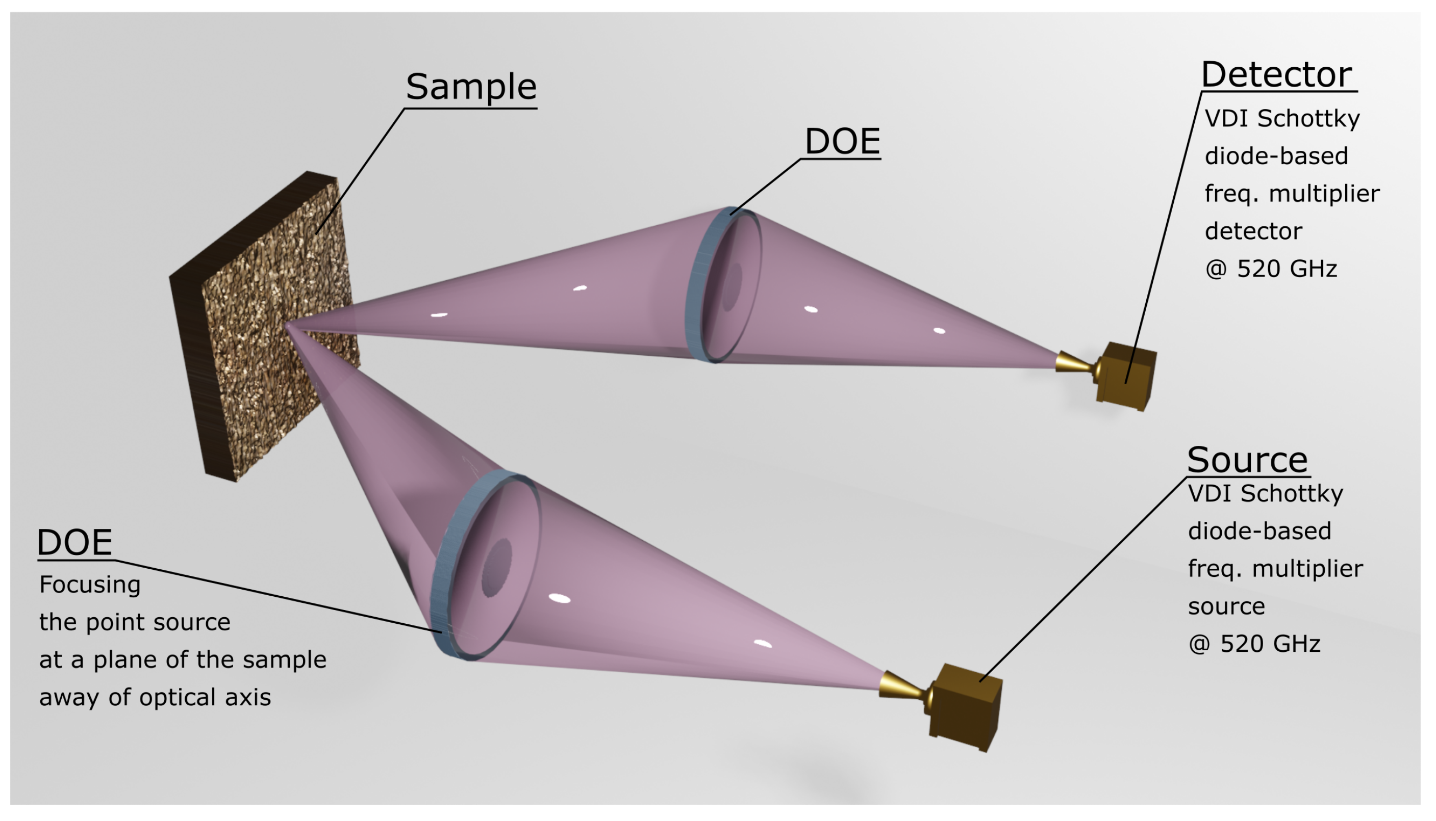
The concept of a compact in-reflection setup for skin cancer diagnosis is presented in
Figure 1. The two designed diffractive optical elements are working in transmission and additionally are redirecting the incident radiation off-axis and focus the beam at a particular distance.
In this approach, two point-to-point lenses are used (marked as DOE). Due to the symmetry of the setup, both lenses can actually be considered to be the same diffractive structure, rotated by
. The structure needs to be thin and light with short focal length, which allows focusing of THz radiation into a small focal spot located outside the contours of the device. These restrictions practically exclude the application of refractive lenses; as such, lenses would be too bulky and heavy [
9]. Using a refractive lens in the described geometry would require either partial illumination of a larger lens or mounting the lens at some angle to the structure [
16]. In the first case, the f-number of the lens would be very small (below 1). Such lenses are extremely thick and challenging to manufacture as refractive structures. In the second case, the focal spot would be very elongated (a sample would be placed at an angle to the focal plane of the lens). On the other hand, redirection of the terahertz radiation with use of mirrors is also possible and commonly used [
17]. However, once again, in the short-focal-length and off-axis focusing design, mirrors would result in unnecessary bulkiness of the system. The redirection and focusing of the radiation with parabolic mirrors at an angle higher than 90
is also challenging. Therefore, our research has been focused on diffractive structures with thickness of the order of several millimeters. Light propagation in the Fresnel region and modified convolution method have been used in numerical simulations [
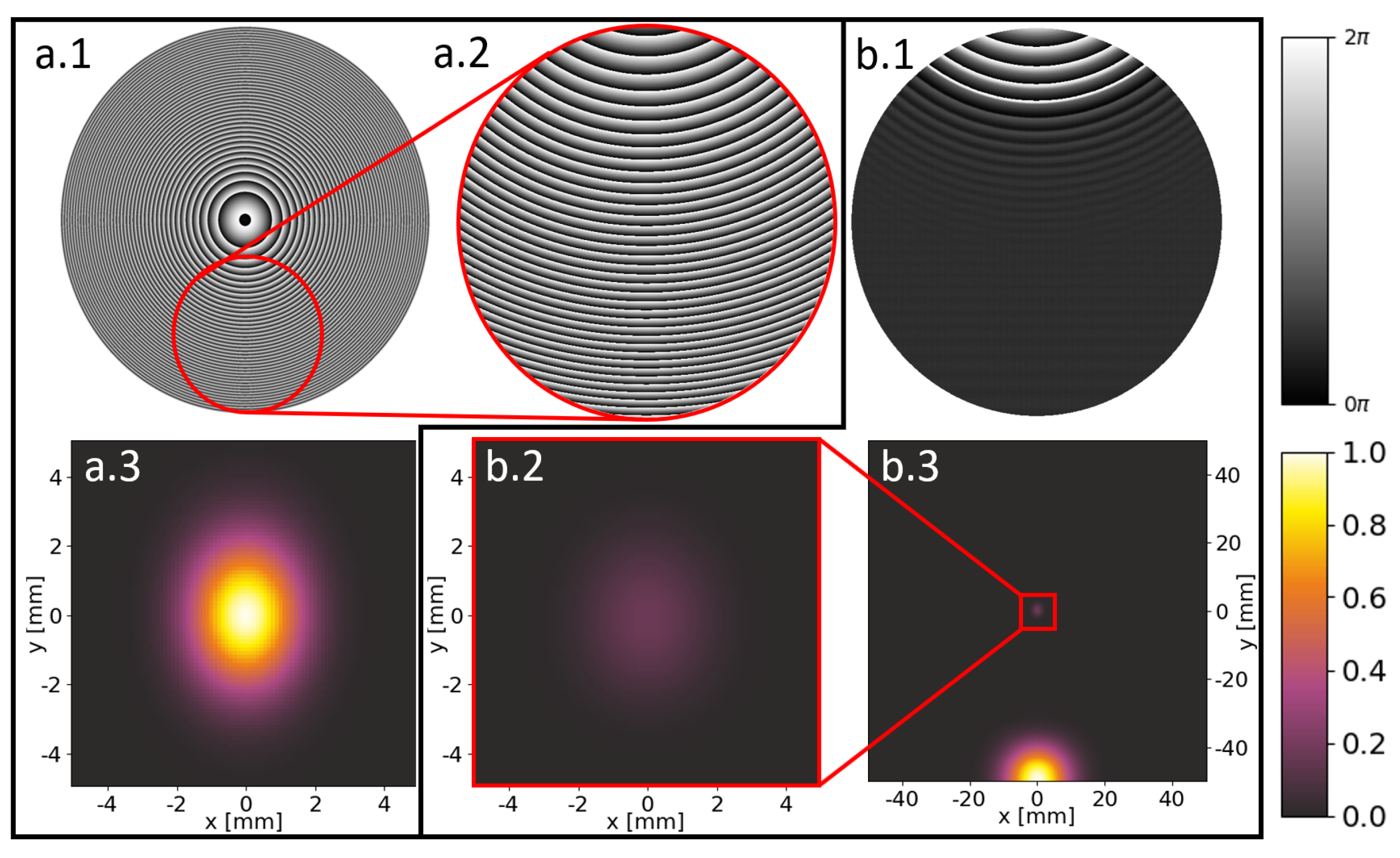
18]. All calculations have been performed on 4096 × 4096 pixels square matrix with 117 m sampling. The design frequency was equal to 520 GHz which corresponds to 0.58 mm design wavelength. Three different design approaches were verified: cutting only part of off-axis lens described by analytical equation, the back-propagation of diffraction-limited focal spot, and the iterative algorithm. In the first method, the diffractive lens is designed according to the lens equation in the non-paraxial approach, and its off-axis part is taken. The second method relies on the definition of the target intensity distribution (ideal focal spot) and propagating it at the negative distance to the lens plane. The third approach, in the simplified view, is based on the iterative implementation of previous two methods. The phase distribution of the structure obtained using the first method can be seen in the top left part of
Figure 2.
A diffractive off-axis lens coded in the form of kinoform with the focal length of 100 mm has been designed. The phase distribution is described by the following equation after applying modulo
operation:
where
is the phase delay introduced by the lens,
r is radial coordinate (calculated from the main optical axis),
is the design wavelength and
f is the focal length. Next the side part of this lens, placed 60 mm from the center and with the diameter of 75 mm, has been cut. In this way, the original focal point is located 100 mm behind the lens plane and 22.5 mm up from its edge, lying outside of the contour of the lens. As it can be seen, this lens focuses radiation in the desired position with a good efficiency, but the spot is relatively big and elongated.
Second approach based on re-propagation of the optical field is shown in
Figure 2b. The ideal focal spot (diffraction-limited intensity distribution with flat phase) is defined in the focal plane. The assumed background of the defined focal spot is not perfectly black, but in the very dark grey shade. It allows the preservation of the information about the phase distribution without affecting the result in any significant way. Then, light is propagated backward to the lens plane and a shifted circular aperture with 75 mm in diameter is cut from the obtained phase distribution (
Figure 2(b.1)). It can be seen that after back-propagation at a distance of 100 mm such a defined phase distribution of light diverges only to a certain diameter. This diameter is insufficient to properly describe off-axis structure with the described above geometrical parameters. As a result, the majority of the lens area is relatively flat and only its top part is active and works as intended. Nevertheless, the focal spot with dimensions smaller than in the first case (using analytical equation) is obtained (
Figure 2(b.2)). However, its intensity is much lower due to the fact that most of the energy is not redirected and forms an unwanted bright region in the middle of the structure. This non-diffracted zeroth order can be seen at the bottom of intensity distribution shown in the
Figure 2(b.3)). The third approach is a combination of previous two cases. The light is propagated back and forth from the lens plane to the focal plane in an iterative algorithm (similar to Gerchberg-Saxton [
19] or ping pong [
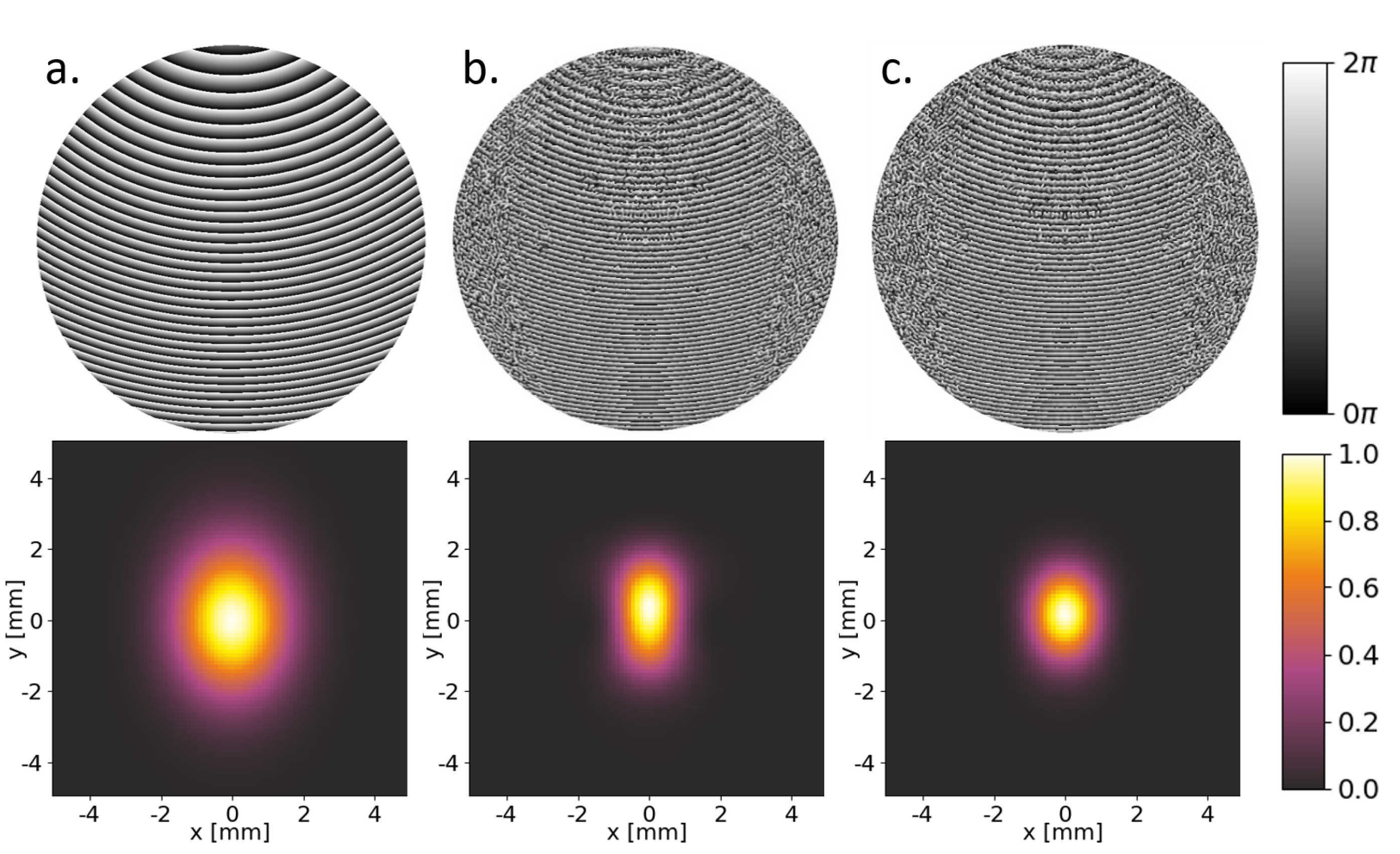
20] algorithms). In the lens plane, the calculated amplitude is overwritten with the amplitude of the incident plane wave, while the amplitude of the ideal focal spot is defined in the focal plane. The phase distribution obtained in the lens plane defines the optimized off-axis lens. The algorithm converges fast and in just a few iterations the output light field distribution matches with the desired one well. The phase distributions in the lens plane and the intensity distributions in the focal plane for first three iterations are shown in
Figure 3.
In the first step, the light is focused by the lens created according to the analytical equation as in the first method. Then the amplitude distribution is replaced by ideal point distribution as in the second method. The amplitude was modified but the phase distribution was maintained as calculated after propagation. Next the light field was propagated back to the lens plane. The new lens is illuminated once more with initial plane wave distribution and the second iteration of algorithm begins. As it can be seen, the second focal spot is already significantly smaller than the first one, but still noticeably elongated. However, in the third step the obtained focal spot is circular and has dimensions in order of diffraction limit. Full widths at half maximum (FWHM) of calculated focal spots are equal to 3.33 mm, 2.22 mm and 1.99 mm, respectively. These values have been obtained by averaging FWHMs for horizontal and vertical axes. The diffraction limit of light for this wavelength and focusing parameters (Airy dot diameter, described as ) is equal to 1.88 mm. Thus, FWHM of the focal spot obtained from the optimized off-axis lens is only higher than the theoretical limit. Further iterations do not provide any significant improvements which was verified in numerical simulations.
4. Experimental Evaluation
The performance of all manufactured structures has been experimentally verified in the setup, shown in the
Figure 4.
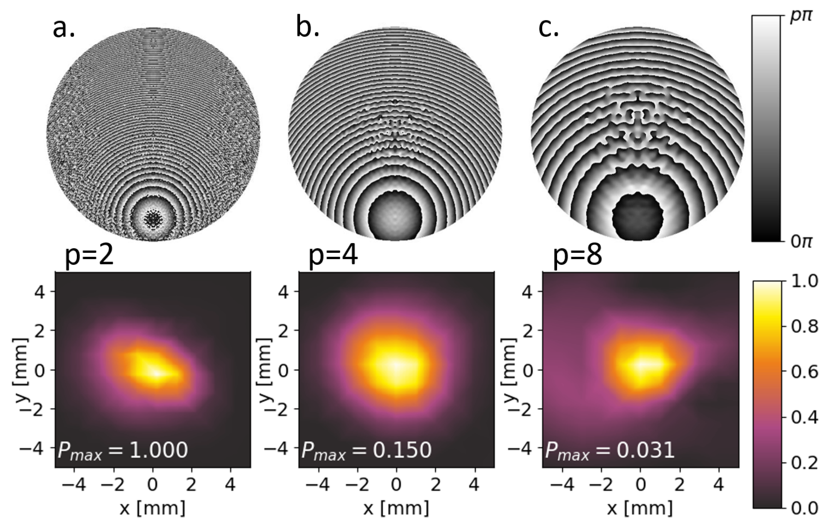
All marked dimensions have been chosen empirically before designing optical elements taking into account dimensions of available sources and detectors as well as total size and usability of a future scanner head. This optical setup consists of two frequency multipliers with Schottky diodes to emit and detect THz radiation with the structure under test in the middle. The comparison of the 1st, the 2nd and the 4th order kinoforms as well as corresponding focal spots are presented in
Figure 5. The scans of the analogous structures performed along the optical axis can be found in our previous paper [
10]. Their character remained the same.
It can be noticed that in subsequent HOKs respective zones are indeed wider proportionally to their order. The designed structures generally resemble Fresnel lenses. Additional discontinuities on the borders of zones (regions where phase drops from
to 0) result from the iterative optimization algorithm and enhance geometric parameters of focal spots. All intensity distributions have been separately normalized for the sake of visibility but measured peak values have been denoted on images as
(in relation to the best performing structure). It can be seen that for kinoforms of higher-order intensity of focal spot significantly decreases (by
for the 2nd order and by almost
for the 4th order kinoform). It is clearly connected with the thickness of the structures. The absorption coefficient of PA12 is already relatively high at 520 GHz (around 2.2 cm
) [
21] and starts to play a significant role when the thickness of the structures is doubled or quadrupled. The transparency issue can be partially solved by application of less attenuating media. However, the number of materials accessible for 3D printing is rather limited. Therefore, another manufacturing method has been proposed based on the additive manufacturing of the molds. These molds correspond to the designed DOEs and then are filled with melted paraffin. Thus, the mold corresponding to the fourth order kinoform has been manufactured and three kinds of paraffin from different manufacturers have been tested. These kinds of paraffin have been marked as b, c and d where b refers to transparent paraffin, c to white paraffin and d to reused paraffin. The experimental results together with reference PA12 lens are shown in
Figure 6.
Here, all power distributions have also been normalized separately and the ratios of recorded maxima to the peak power obtained from reference lens are denoted as . The intensities of focal spots obtained for all three paraffin HOKs are significantly higher than the one from PA12 lens (by 42%, 76% and 36%, respectively). On the other hand, differences between very similar paraffin samples obtained from different distributors are also far from being negligible. Finding the reasons for that would require more in-depth study, especially of the differences between materials. Initial measurements show that different types of waxes and paraffins have significantly different THz optical properties.
5. Shorter Focal Lengths
As a proposed design method has proved to be successful in designing off-axis lens-like structures with the focal length equal to 100 mm, the additional simulations have been performed. These numerical calculations allowed determination of how short the focal length can be while maintaining good geometrical parameters of the focal spot. The diameters of lenses have been cropped to 50 mm in all these simulations. However, it must be noted that here as well as in previously described cases the reconstructing beam is described with flat phase and Gaussian intensity distribution. It means that the introduced 50 mm aperture has not limited active structure region significantly. The phase distributions of four lens-structures with focal lengths varying from 50 mm to 10 mm together with the corresponding focal spots are presented in
Figure 7.
The longest focal length chosen to be shown in this figure is 50 mm, as no significant changes can be observed in the intensity distribution for longer focal lengths (like the 100 mm focal spot shown in
Figure 3 and
Figure 5). On the other hand, distortions from the circularity of the focal spot become more and more visible for smaller focal lengths. For
mm the focal spot is already significantly elongated, while for
mm it resembles a stripe not a dot.
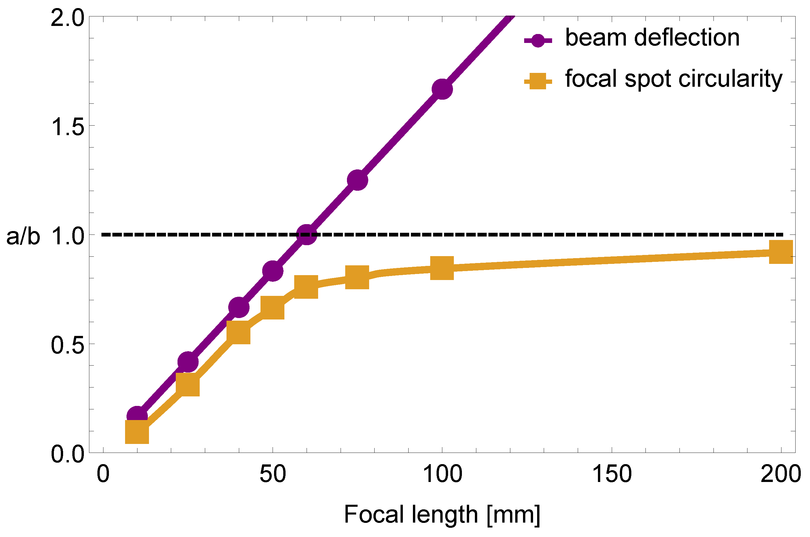
The additional study on the shape of focal spots is presented in
Figure 8.
The orange line denotes circularity of the focal spots, calculated as the ratio of the diameters of the spots measured along horizontal (a) and vertical (b) axes. The violet line corresponds to the degree of the deflection of the incident beam—in this case it is simply a tangent of the angle between the lens surface and the deflected beam. The circularity equal to one would denote the perfect circle, but the smaller focal length the closer it gets to zero. It means that the shape is more elliptical. The dependence of the spot circularity on the focal length is in the shape of two lines with different slopes, crossing around focal length which equals to 60 mm. As it can be seen in the
Figure 8, for longer focal lengths the dependence is almost flat while for shorter ones the curve is almost parallel to the beam deflection line (up to the value of circularity equal to 1). Mathematically, this curve can be described by two asymptotes, as in Equation (
2):
The long-focal-length-limit behavior of the curve is easily understandable, as the shift from the main optical axis to the center of the structure becomes much smaller than the focal length. In this case the structure starts to neglect off-axis requirements and it is focusing almost on-axis with the perfect circular focal spot. The interesting behavior is observed for a short-focal-length-limit as the curve approaches tangent of the deflection angle of the THz beam. It seems to be the fundamental limit of off-axis focal spot circularity, at least in this design method. The breakthrough point lies at 60 mm, where the focal length is equal to the shift from the optical axis and two asymptotes intersect.
6. Summary
The off-axis diffractive lens-like structures for THz spectral range have been designed, manufactured and tested. The applicability of the higher-order kinoforms has been shown. They offer a better manufacturing quality at the expense of the increased losses introduced by the structure thickness. The further work aims at solving this issue by changing the used PA12 material for the one with the lower absorption coefficient (paraffin). The paraffin lenses manufactured by filling 3D-printed molds are currently considered to be the most promising option and have shown satisfactory results.
Additional study on the shape of focal spots circularity for different focal lengths has been conducted. Summarizing, the changing point between off and on-axis approaches can be set for the focal length of the structure equal to the shift of the structure from the main optical axis.
All simulations and experimental evaluation have allowed determination that the smallest focal length of structures is equal to 50 mm for the configuration of the optical setup proposed here for in-reflection skin cancer scanners. At the same time, it needs to be remembered that in the proposed setup the middle of the structure is shifted 60 mm from the main optical axis.
The analysis of the structures allowed determination of to what extend the setup can be minimized. The off-axis focusing is challenging, as tremendous aberrations are observed. The beam deflection angle for the proposed lens is equal to almost 31. For the shortest focal length with acceptable distortions of the focal spot ( mm) the mentioned angle even reaches 51. It is well beyond the limits of paraxial approximation (which can be applied up to approx. 17–18). The iterative algorithms proposed in this article allow significant reduction of the undesired aberration effects and obtain higher quality of the off-axis focal spots.
